EP0859203A2 - Verfahren und Vorrichtung zum Kühlen von Luft - Google Patents
Verfahren und Vorrichtung zum Kühlen von Luft Download PDFInfo
- Publication number
- EP0859203A2 EP0859203A2 EP98200447A EP98200447A EP0859203A2 EP 0859203 A2 EP0859203 A2 EP 0859203A2 EP 98200447 A EP98200447 A EP 98200447A EP 98200447 A EP98200447 A EP 98200447A EP 0859203 A2 EP0859203 A2 EP 0859203A2
- Authority
- EP
- European Patent Office
- Prior art keywords
- heat exchanger
- canalization
- plates
- air stream
- secondary canalization
- Prior art date
- Legal status (The legal status is an assumption and is not a legal conclusion. Google has not performed a legal analysis and makes no representation as to the accuracy of the status listed.)
- Withdrawn
Links
- 238000001816 cooling Methods 0.000 title claims abstract description 32
- 238000000034 method Methods 0.000 title claims abstract description 32
- 239000012530 fluid Substances 0.000 claims abstract description 41
- XLYOFNOQVPJJNP-UHFFFAOYSA-N water Substances O XLYOFNOQVPJJNP-UHFFFAOYSA-N 0.000 claims abstract description 7
- 230000008016 vaporization Effects 0.000 claims abstract description 3
- 238000001704 evaporation Methods 0.000 claims description 17
- 230000008020 evaporation Effects 0.000 claims description 17
- 230000000694 effects Effects 0.000 claims description 15
- 239000011248 coating agent Substances 0.000 claims description 11
- 238000000576 coating method Methods 0.000 claims description 11
- 238000000605 extraction Methods 0.000 claims description 11
- 230000006835 compression Effects 0.000 claims description 5
- 238000007906 compression Methods 0.000 claims description 5
- 230000001105 regulatory effect Effects 0.000 claims description 4
- 239000002274 desiccant Substances 0.000 claims description 3
- 239000012528 membrane Substances 0.000 claims description 3
- VYPSYNLAJGMNEJ-UHFFFAOYSA-N Silicium dioxide Chemical compound O=[Si]=O VYPSYNLAJGMNEJ-UHFFFAOYSA-N 0.000 claims description 2
- 230000002745 absorbent Effects 0.000 claims description 2
- 239000002250 absorbent Substances 0.000 claims description 2
- 239000004744 fabric Substances 0.000 claims description 2
- 239000000741 silica gel Substances 0.000 claims description 2
- 229910002027 silica gel Inorganic materials 0.000 claims description 2
- 238000001035 drying Methods 0.000 claims 4
- 238000010586 diagram Methods 0.000 description 9
- 239000007921 spray Substances 0.000 description 6
- 238000007789 sealing Methods 0.000 description 3
- 239000007788 liquid Substances 0.000 description 2
- 239000004743 Polypropylene Substances 0.000 description 1
- 238000000889 atomisation Methods 0.000 description 1
- 230000005540 biological transmission Effects 0.000 description 1
- 230000015572 biosynthetic process Effects 0.000 description 1
- 239000004020 conductor Substances 0.000 description 1
- 238000005260 corrosion Methods 0.000 description 1
- 230000007797 corrosion Effects 0.000 description 1
- 238000005265 energy consumption Methods 0.000 description 1
- 230000012447 hatching Effects 0.000 description 1
- 239000000463 material Substances 0.000 description 1
- 239000002184 metal Substances 0.000 description 1
- 230000000414 obstructive effect Effects 0.000 description 1
- 239000004417 polycarbonate Substances 0.000 description 1
- 229920000515 polycarbonate Polymers 0.000 description 1
- -1 polypropylene Polymers 0.000 description 1
- 229920001155 polypropylene Polymers 0.000 description 1
- 230000002787 reinforcement Effects 0.000 description 1
- 230000000717 retained effect Effects 0.000 description 1
- 238000010079 rubber tapping Methods 0.000 description 1
- 229920006395 saturated elastomer Polymers 0.000 description 1
- 230000000087 stabilizing effect Effects 0.000 description 1
- 229920002994 synthetic fiber Polymers 0.000 description 1
Images


Classifications
-
- F—MECHANICAL ENGINEERING; LIGHTING; HEATING; WEAPONS; BLASTING
- F24—HEATING; RANGES; VENTILATING
- F24F—AIR-CONDITIONING; AIR-HUMIDIFICATION; VENTILATION; USE OF AIR CURRENTS FOR SCREENING
- F24F5/00—Air-conditioning systems or apparatus not covered by F24F1/00 or F24F3/00, e.g. using solar heat or combined with household units such as an oven or water heater
- F24F5/0007—Air-conditioning systems or apparatus not covered by F24F1/00 or F24F3/00, e.g. using solar heat or combined with household units such as an oven or water heater cooling apparatus specially adapted for use in air-conditioning
-
- F—MECHANICAL ENGINEERING; LIGHTING; HEATING; WEAPONS; BLASTING
- F24—HEATING; RANGES; VENTILATING
- F24F—AIR-CONDITIONING; AIR-HUMIDIFICATION; VENTILATION; USE OF AIR CURRENTS FOR SCREENING
- F24F1/00—Room units for air-conditioning, e.g. separate or self-contained units or units receiving primary air from a central station
- F24F1/0007—Indoor units, e.g. fan coil units
- F24F1/0059—Indoor units, e.g. fan coil units characterised by heat exchangers
-
- F—MECHANICAL ENGINEERING; LIGHTING; HEATING; WEAPONS; BLASTING
- F24—HEATING; RANGES; VENTILATING
- F24F—AIR-CONDITIONING; AIR-HUMIDIFICATION; VENTILATION; USE OF AIR CURRENTS FOR SCREENING
- F24F1/00—Room units for air-conditioning, e.g. separate or self-contained units or units receiving primary air from a central station
- F24F1/0007—Indoor units, e.g. fan coil units
-
- F—MECHANICAL ENGINEERING; LIGHTING; HEATING; WEAPONS; BLASTING
- F28—HEAT EXCHANGE IN GENERAL
- F28D—HEAT-EXCHANGE APPARATUS, NOT PROVIDED FOR IN ANOTHER SUBCLASS, IN WHICH THE HEAT-EXCHANGE MEDIA DO NOT COME INTO DIRECT CONTACT
- F28D5/00—Heat-exchange apparatus having stationary conduit assemblies for one heat-exchange medium only, the media being in contact with different sides of the conduit wall, using the cooling effect of natural or forced evaporation
-
- F—MECHANICAL ENGINEERING; LIGHTING; HEATING; WEAPONS; BLASTING
- F28—HEAT EXCHANGE IN GENERAL
- F28D—HEAT-EXCHANGE APPARATUS, NOT PROVIDED FOR IN ANOTHER SUBCLASS, IN WHICH THE HEAT-EXCHANGE MEDIA DO NOT COME INTO DIRECT CONTACT
- F28D9/00—Heat-exchange apparatus having stationary plate-like or laminated conduit assemblies for both heat-exchange media, the media being in contact with different sides of a conduit wall
- F28D9/0025—Heat-exchange apparatus having stationary plate-like or laminated conduit assemblies for both heat-exchange media, the media being in contact with different sides of a conduit wall the conduits being formed by zig-zag bend plates
Definitions
- the present invention concerns a method and device for cooling air.
- the invention aims a method and device with which these disadvantages are excluded, in other words with which air can be cooled very efficiently in a relatively inexpensive manner with little energy consumption. It is meant in particular for applications in which the use of compression cooling devices is not economically feasible, but in fact it can be used for any application whatsoever.
- the invention concerns a method for cooling air, characterized in that it consists in the cooling of an air stream on the one hand by sending it through a primary canalization of a heat exchanger, and by vaporizing fluid, in particular water, in a secondary canalization of this heat exchanger on the other hand by means of an auxiliary air stream which is tapped off the air stream leaving the primary canalization.
- the fluid to be evaporated is hereby sprayed or atomized on the walls of the secondary canalization or provided on it in any other way whatsoever.
- a heat exchanger with plates use is preferably made of a heat exchanger with plates. This offers the advantage that very large evaporation surfaces are created, so that the auxiliary air stream can be limited to a minimum and so that there is little loss of energy.
- the use of a heat exchanger with plates also offers the advantage that large surfaces can be easily moistened by means of one and the same spray device.
- the moisture is sprayed on the plates, atomized respectively, with drops having a size in the order of 100 to 300 micrometre, which produces the best evaporation effect.
- the auxiliary air stream is cooled and/or dried before it can be guided through the secondary canalization.
- the air of the auxiliary air stream can absorb more moisture, which promotes the evaporation of the fluid.
- care will be taken, in any way whatsoever, that the air of the auxiliary air stream is supplied to the heat exchanger with a relative air humidity which is lower than 80%.
- a relative air humidity which is lower than 80%.
- the auxiliary air stream in the secondary canalization will be preferably guided in the upward direction through the heat exchanger.
- the auxiliary air stream is not counteracted by the chimney effect of the hot, damp air which occurs in the secondary canalization, so that the auxiliary air stream is made more efficient.
- measures are taken which make sure that the air of the auxiliary air stream is evenly distributed through the secondary canalization of the heat exchanger.
- these measures make sure that no parts are created in the secondary canalization in which the air stands practically still.
- the air supply and/or the air extraction according to the invention will preferably be realized in a direction which extends diagonally or almost diagonally on the plates of the heat exchanger in order to make sure that the auxiliary air stream flows evenly distributed through the secondary canalization.
- an obstruction is provided on the inlet of the secondary canalization, which is provided with passages in the shape of perforations, holes or such.
- the walls of the secondary canalization are provided with means which retain the fluid on the one hand, but which also distribute it over the surface concerned on the other hand.
- these are means which provide for a hygroscopic surface.
- these means will consist of a hygroscopic coating, preferably in the shape of a hygroscopic membrane, cloth or such.
- the use of such means offers the advantage that the moisture is optimally distributed over the surface and is retained on the surface.
- This in turn offers the advantage that the walls of the secondary canalization will be moistened with great certainty over their entire surface, so that an evaporation and cooling takes place over the entire surface.
- This also offers the advantage that fluctuations in the supply of moisture do not immediately result in excess fluid running out of the canalization, so that a receptacle can possibly be omitted.
- the fluid to be evaporated will preferably be supplied in the secondary canalization counterflow in relation to the auxiliary air stream. This optimally prevents moisture pollution in the dry parts of the device. Moreover, all the supplied fluid will be evaporated with great certainty, and it is practically excluded that an excess of unevaporated fluid is created on the inlet of the secondary canalization.
- canalizations are used both for the main air stream and for the auxiliary air stream which do not have any open receptacles and/or leak-off ladles.
- all the supplied fluid will preferably be evaporated according to the invention, so that collecting means such as a receptacle or leak-off ladle are no longer necessary.
- the invention also concerns a device for cooling air which makes it possible to realize the above-mentioned method.
- This invention consists of a heat exchanger having a primary canalization and a secondary canalization; means which put fluid on the walls of the secondary canalization so as to create a cooling effect due to evaporation; pipes which provide for a main circuit through the primary canalization and an auxiliary circuit through the secondary canalization, whereby the auxiliary circuit forms a branch on the main circuit, downstream of the primary canalization; and means to create the above-mentioned air stream and auxiliary air stream.
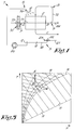
- the device 1 mainly consists of a heat exchanger 2, in this case a heat exchanger with plates with a primary canalization 3 and a secondary canalization 4; spray means 5 which can put finely divided fluid 6 on the walls of the secondary canalization 4 so as to create a cooling effect due to evaporation; pipes which are not represented, providing in a main circuit 7 through the primary canalization 3 and in an auxiliary circuit 8 through the secondary canalization 4, whereby the auxiliary circuit 8 forms a branch on the main circuit 7, whose branching point 9 is situated downstream of the primary canalization 3; and means 10 to create an air stream 11 through the primary canalization 3 and an auxiliary air stream 12 through the secondary canalization 4.
- a heat exchanger 2 in this case a heat exchanger with plates with a primary canalization 3 and a secondary canalization 4
- spray means 5 which can put finely divided fluid 6 on the walls of the secondary canalization 4 so as to create a cooling effect due to evaporation
- pipes which are not represented, providing in a main circuit 7 through the primary canalization
- the heat exchanger 2 consists of a number of plates 13-14 situated next to one another, in between which rooms 15-16 are provided which alternately form passages for the air stream 11 and the auxiliary air stream 12.
- the inlets, outlets respectively of these rooms 15-16 are situated such that, as represented in the figures, the air stream 11 and the auxiliary air stream 12 intersect one another in the heat exchanger 2.
- the means 10 to create the air stream 11 and the auxiliary air stream 12 consist of one common fan 17 in the example represented, but it is clear that several fans or such can be incorporated in the main circuit 7 and/or the auxiliary circuit 8.
- the heat exchanger 2 is erected such in this example that the secondary canalization 4 extends from top to bottom. Under the heat exchanger 2 is erected a receptacle 18 to collect any moisture dripping down.
- the above-mentioned spray means 5 in this case consists of a sprinkler 19 which is fed by means of a pump 20 or such, tapping fluid 6, in particular water, from the receptacle 18.
- the level of the fluid 6 in the receptacle 18 is maintained thanks to a connection to a supply net 21, preferably a mains system for water.
- the level in the receptacle 18 can hereby be adjusted by means of a valve 22 which is controlled by a float 23.
- the sprinkler 19 which in reality may have several sprinkler heads, is situated above the set of plates 13-14 and is made such that the fluid 6 concerned is sprayed over the entire surface of the plates 13-14.
- the working of the device 1, as well as the accompanying method, consists in that an air stream 11 is sent through the primary canalization 3 by the means 10. This air stream 11 is split in a main air stream 24 and an auxiliary air stream 12. The auxiliary air stream 12 makes sure that the fluid 6 sprayed on the plates 13-14 by means of the spray means 5 evaporates.
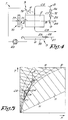
- the different situations A, B and C which are represented in the diagram of figure 3, are situations which may occur in the places which are correspondingly indicated by A, B and C in figure 1.
- a cooling temperature is created on the plates 13-14 which is almost equal to the wet point temperature in point C of the diagram.
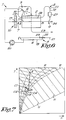
- Figure 4 represents a variant in which a cooler 25 and a heat source 26, together forming a drier and which are either or not combined in one appliance, are incorporated between the above-mentioned branch point 9 and the secondary canalization 4 of the heat exchanger 2.
- This is preferably a conventional cooler 25 providing for a compression cooling.
- the heat source is preferably adjusted such that the relative humidity of the auxiliary air stream remains below 80% behind the drier.
- Figure 6 represents a variant of the device 1 whereby use is made of a drier 27 in the auxiliary circuit 8 provided with a drying agent which can be regenerated, for example silica gel.
- the air coming from this drier 27 will normally be cooled before it is used for the evaporation of the fluid 6 in the secondary canalization 4.
- the heat exchanger 2 is provided in an auxiliary canalization 28 for the cooling of the auxiliary air stream 12.
- auxiliary canalization 28 which consists of a heat exchanger provided in the main air stream behind the branching point 9.
- Figure 8 schematically represents a variant whereby the plates 13-14 are erected key-shaped, such that the secondary canalization 4 narrows according to the direction of flow.
- the fluid 6 sprayed between the plates 13-14 can efficiently cover the entire surface of these plates 13-14, even when the sprinkler 19 is situated above these plates 13-14.
- the device 1 is also equipped with an element 29 such as a perforated plate to distribute the air evenly over the different rooms 16 of the secondary canalization 4, so that the air is optimally used for the evaporation and so that the flow rate of the auxiliary air stream 12 can be limited to a minimum.
- an element 29 such as a perforated plate to distribute the air evenly over the different rooms 16 of the secondary canalization 4, so that the air is optimally used for the evaporation and so that the flow rate of the auxiliary air stream 12 can be limited to a minimum.
- Figure 9 further illustrates how the whole can be provided with pipes or ducts 30, 31 and 32 to guide the supplied air stream 11, the auxiliary air stream 12 and the main air stream 24.
- the main air stream 24 hereby forms the useful part of cooled air.
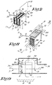
- Figure 10 shows a section of yet another part of a practical embodiment, whereby guiding means 33 in the shape of ribs 34-35-36-37 are provided in the primary canalization 3 which force the air of the air stream 11 to the narrowest part 38 of the rooms 15 so as to obtain an optimal heat transmission.
- the ribs 34-35 are hereby provided on the plates 13.
- the ribs 36-37 are provided on the plates 14 and end up between the ribs 34-35 when the whole is mounted, as indicated in figures 11 and 12.
- guiding means are also provided in the secondary canalization 4 which promote the intersected circulation and which consist of ribs 39-40 in this case.
- the ribs 34-35-36-37-39-40 also form reinforcements for the plates 13-14.
- the plates 13-14 are preferably clasped together with their edges in this case.
- a large number of difficult connections is excluded.
- the key-shaped rooms 15-16 preferably have an opening of about 2.5 mm wide on their narrowest side and an opening of about 7.5 mm wide on their widest side.
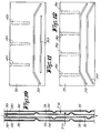
- the auxiliary air stream 12 can be guided from top to bottom through the heat exchanger 2 and good results can be obtained, the inventor found that these results can even be significantly improved by guiding the auxiliary air stream 12, according to a preferred characteristic of the invention, in the upward direction through the heat exchanger, either vertically, as represented in figures 13 to 15, or upward in a diagonal direction.
- the chimney effect is meant the natural phenomenon that hot air has a tendency to rise by itself.
- a lead-through of the auxiliary air stream 12 may have for a result that certain wall parts 41, which are schematically represented in figure 16 by means of a hatching, participate little in the evaporation process, as the flow rate of the air stream moving alongside of them is too low, due to the fact that the auxiliary air stream 12 tries to find the easiest way.
- this can be remedied by making sure that the air of the auxiliary air stream flows evenly distributed through the secondary canalization 4 of the heat exchanger 2.
- use can be made to this end of an element 29 which is provided on the inlet of the secondary canalization 4, which forms an obstruction and is provided with perforations or such.
- the use of such an element 29 or any other obstructive element can be excluded while an even distribution is nevertheless obtained by having the air supply 42 and/or air extraction 43 take place right before and right behind the plates 13-14 according to a direction which extends diagonally or almost diagonally on the plates 13-14, with the help of suitable ducts 44 and 45, as represented in figures 13 to 15.
- the creation of wall parts 41 alongside which the flow of air is practically zero is excluded.
- the walls 46 of the secondary canalization 4 are provided with a hygroscopic coating 47, in this case a membrane which is provided against the walls 46, for example stretched around it.
- This coating 47 directly and indirectly offers several advantages, including the following:
- the plates 13-14 of the above-mentioned heat exchangers 2 will preferably be erected upright, and the air stream 11 will be mainly guided in the horizontal direction through the heat exchanger 2, whereas the auxiliary air stream 12 will be mainly guided through it in the vertical direction, whereas the air supply 42, the air extraction 43 respectively, of the auxiliary air stream 12 on the plates 13-14 takes place laterally, as is clearly shown in figure 14.
- the fluid 6 to be evaporated is supplied counterflow as of the outlet of the secondary canalization 4, which, as explained in the introduction, offers several extra advantages.
- the sprinkler 19 can hereby make a rotating movement F to and fro.
- the figures 13 to 15 and 18 also show that a heat exchanger 2 can be used according to the invention which does not have a receptacle, as opposed to for example the embodiment of figure 1, in which such a receptacle 18 is used. This offers the advantage that the air no longer has to be guided over a liquid mass and consequently cannot arbitrarily absorb any moisture.
- the amount of supplied fluid 6 must be dosed such in this case that it can evaporate entirely, in other words such that there is no dripping moisture.
- a controlled regulating valve 51 can be controlled by means of a control unit 51A and/or a sensor which supplies measured values which are directly or indirectly representative for the moistening degree in the secondary canalization or by means of any feedback whatsoever.
- the heat exchanger 2 is preferably built up of longitudinal plates 13-14 according to a preferred embodiment.
- the distance D1 between the plates of the secondary canalization 4 will be smaller than 5 mm. This relatively small distance offers as an advantage that no excess air, which produces no evaporation effect, will flow through the secondary canalization.
- the heat exchanger 2 will have a flow-through length L1 between the plates in the primary canalization 3 of 40 to 80 cm.
- the number of plates 13-14 can be selected as a function of the flow rate to be treated. In practical embodiments, this number will be several times ten and even 100 to 200.
- the plates 13-14 themselves can be made of a thin and good heat-conducting material, for example a thin metal plate. However, it was found that also other materials provided good results on condition that the plates 13-14 are maintained relatively thin. According to the invention, the plates 13-14 will preferably even be made of synthetic material, which offers the advantage that a heat exchanger 2 is obtained which is highly corrosion-resistant and which can be realized in a relatively inexpensive manner.
- the plates 13-14 will be made of polycarbonate plate or polypropylene plate, for example with a thickness D2 of 0.3 mm.
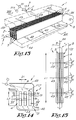
- Figures 19 and 20 represent a practical embodiment in which the above-mentioned plates 13-14 are made continuously of a single corrugated plate 53, whereby the spaces 15-16 provided alternately in between are used for the formation of the primary canalization 3, the secondary canalization 4 respectively.
- a sealing wall 54 is provided on one side against said corrugated plate 53.
- passages 55 are provided which connect the space under this sealing element 54 to the above-mentioned spaces 16.
- corrugated plate 53 offers the advantage that the whole can be realized in a relatively simple manner, as no separate plate structure has to be build up.
- corrugated plate 53 will preferably be formed starting from a flat plate, which plate will subsequently be heated, and by deforming this heated plate by sucking it in over a comb-shaped mould.
- auxiliary air stream 12 is also formed in this case near the inlet, as the air has to flow locally through the passages 55. This results in a slight pressure increase in the space under the sealing wall 54, so that the air is forced to spread entirely over this space and to flow through all the passages 55.
- a forced extraction will preferably be provided for, by means of for example a fan 56, which is only represented as an example in figure 18.
- the means for supplying the fluid 6 do not necessarily have to be spray means. Especially in the case where use is made of an absorbent or hygroscopic coating 47, a fine atomization is not necessary and one could for example also use a drip system or such.
- an auxiliary air stream 12 will preferably also be provided with such a flow rate that the refreshment of the air in the secondary canalization 4 takes one to three volume units per second, whereby by a volume unit is meant the volume of air available in the secondary canalization 4, in particular between the plates 13-14 or other heat transfer elements of the heat exchanger 2.
- the invention also concerns embodiments whereby only a part of the auxiliary air stream is supplied via the branch, and whereby the other part is for example drawn from the environment via a separate suction.
Landscapes
- Engineering & Computer Science (AREA)
- Mechanical Engineering (AREA)
- General Engineering & Computer Science (AREA)
- Physics & Mathematics (AREA)
- Thermal Sciences (AREA)
- Chemical & Material Sciences (AREA)
- Combustion & Propulsion (AREA)
- Life Sciences & Earth Sciences (AREA)
- Sustainable Development (AREA)
- Heat-Exchange Devices With Radiators And Conduit Assemblies (AREA)
- Motor Or Generator Cooling System (AREA)
Priority Applications (2)
| Application Number | Priority Date | Filing Date | Title |
|---|---|---|---|
| AU87951/98A AU8795198A (en) | 1998-02-13 | 1998-08-06 | Method and device for cooling air |
| PCT/BE1998/000121 WO1999041552A1 (en) | 1998-02-13 | 1998-08-06 | Method and device for cooling air |
Applications Claiming Priority (2)
| Application Number | Priority Date | Filing Date | Title |
|---|---|---|---|
| BE9700136A BE1010922A6 (nl) | 1997-02-13 | 1997-02-13 | Werkwijze en inrichting voor het koelen van lucht. |
| BE9700136 | 1997-02-13 |
Publications (2)
| Publication Number | Publication Date |
|---|---|
| EP0859203A2 true EP0859203A2 (de) | 1998-08-19 |
| EP0859203A3 EP0859203A3 (de) | 1998-11-25 |
Family
ID=3890341
Family Applications (1)
| Application Number | Title | Priority Date | Filing Date |
|---|---|---|---|
| EP98200447A Withdrawn EP0859203A3 (de) | 1997-02-13 | 1998-02-13 | Verfahren und Vorrichtung zum Kühlen von Luft |
Country Status (2)
| Country | Link |
|---|---|
| EP (1) | EP0859203A3 (de) |
| BE (1) | BE1010922A6 (de) |
Cited By (6)
| Publication number | Priority date | Publication date | Assignee | Title |
|---|---|---|---|---|
| DE10329764A1 (de) * | 2003-07-01 | 2005-02-03 | Frank Zegula | Luftkühlgerät auf Wasserverdunsterbasis mit hermetischer Trennung des Kühlmediums zu der abzukühlenden Luft, insbesondere für Fahrzeuge (Wohnmobile, Wohnwagen, Busse etc.) und Räume |
| WO2005019739A1 (en) * | 2003-08-20 | 2005-03-03 | Oxycell Holding Bv | Heat exchange element |
| EP1538398A3 (de) * | 2003-12-05 | 2006-11-08 | 2H KUNSTSTOFF GmbH | Kontaktkörper, insbesondere für einen Verdunstungsbefeuchter, und Verfahren zur Herstellung eines Kontaktkörpers |
| EP1887303A3 (de) * | 2006-08-08 | 2013-04-10 | Behr GmbH & Co. KG | Wärmeübertragung und Verfahren zur Herstellung eines solchen Wärmeübertragers |
| WO2013120600A3 (de) * | 2012-02-17 | 2013-10-24 | Kampmann Gmbh | Vorrichtung zur kühlung und/oder wärmerückgewinnung |
| RU2741182C1 (ru) * | 2020-09-17 | 2021-01-22 | Федеральное государственное бюджетное образовательное учреждение высшего образования «Уральский государственный горный университет» | Воздушный пластинчатый рекуператор |
Family Cites Families (3)
| Publication number | Priority date | Publication date | Assignee | Title |
|---|---|---|---|---|
| SE383777B (sv) * | 1973-07-18 | 1976-03-29 | Munters Ab Carl | Sett och anordning for kylning av luft |
| FI67259C (fi) * | 1983-03-21 | 1990-09-17 | Ilmateollisuus Oy | Ventilationssystem. |
| US4660390A (en) * | 1986-03-25 | 1987-04-28 | Worthington Mark N | Air conditioner with three stages of indirect regeneration |
-
1997
- 1997-02-13 BE BE9700136A patent/BE1010922A6/nl not_active IP Right Cessation
-
1998
- 1998-02-13 EP EP98200447A patent/EP0859203A3/de not_active Withdrawn
Cited By (10)
| Publication number | Priority date | Publication date | Assignee | Title |
|---|---|---|---|---|
| DE10329764A1 (de) * | 2003-07-01 | 2005-02-03 | Frank Zegula | Luftkühlgerät auf Wasserverdunsterbasis mit hermetischer Trennung des Kühlmediums zu der abzukühlenden Luft, insbesondere für Fahrzeuge (Wohnmobile, Wohnwagen, Busse etc.) und Räume |
| WO2005019739A1 (en) * | 2003-08-20 | 2005-03-03 | Oxycell Holding Bv | Heat exchange element |
| EP1538398A3 (de) * | 2003-12-05 | 2006-11-08 | 2H KUNSTSTOFF GmbH | Kontaktkörper, insbesondere für einen Verdunstungsbefeuchter, und Verfahren zur Herstellung eines Kontaktkörpers |
| EP1887303A3 (de) * | 2006-08-08 | 2013-04-10 | Behr GmbH & Co. KG | Wärmeübertragung und Verfahren zur Herstellung eines solchen Wärmeübertragers |
| WO2013120600A3 (de) * | 2012-02-17 | 2013-10-24 | Kampmann Gmbh | Vorrichtung zur kühlung und/oder wärmerückgewinnung |
| CN104204685A (zh) * | 2012-02-17 | 2014-12-10 | 科普麦恩有限公司 | 用于冷却和/或用于热回收的设备 |
| US20150021001A1 (en) * | 2012-02-17 | 2015-01-22 | Kampmann Gmbh | Device for cooling and/or heat recovery |
| AU2013220720B2 (en) * | 2012-02-17 | 2017-05-25 | Kampmann Gmbh | Device for cooling and/or heat recovery |
| RU2671766C2 (ru) * | 2012-02-17 | 2018-11-06 | Кампманн Гмбх | Устройство для охлаждения и/или для рекуперации тепла |
| RU2741182C1 (ru) * | 2020-09-17 | 2021-01-22 | Федеральное государственное бюджетное образовательное учреждение высшего образования «Уральский государственный горный университет» | Воздушный пластинчатый рекуператор |
Also Published As
| Publication number | Publication date |
|---|---|
| BE1010922A6 (nl) | 1999-03-02 |
| EP0859203A3 (de) | 1998-11-25 |
Similar Documents
| Publication | Publication Date | Title |
|---|---|---|
| KR100196791B1 (ko) | 열교환 방법및, 열교환장치 | |
| US4002040A (en) | Method of cooling air and apparatus intended therefor | |
| US5301518A (en) | Evaporative air conditioner unit | |
| CN100549610C (zh) | 露点冷却器 | |
| JPH03500923A (ja) | 間接蒸発式ガス冷却装置 | |
| DE2944027A1 (de) | Ejektor-raumklimageraet der zentral-klimaanlage | |
| US4926656A (en) | Integrated wet bulb depression air cooler | |
| FI106223B (fi) | Lämmönvaihdin | |
| WO1999041552A1 (en) | Method and device for cooling air | |
| EP0859203A2 (de) | Verfahren und Vorrichtung zum Kühlen von Luft | |
| WO2020074587A1 (de) | Wärmetauschereinrichtung mit adiabatischem luftkühler | |
| NL1022799C2 (nl) | Dauwpuntskoeler met losneembare irrigatiemiddelen. | |
| US5931017A (en) | Arrangement for cooling supply air in an air-conditioning installation | |
| NL8401778A (nl) | Dauwpuntskoeler. | |
| EP0915312B1 (de) | Kühlturm | |
| WO2018051157A1 (en) | Water distribution systems for plate heat and mass exchanger for indirect evaportive cooling | |
| RU2073174C1 (ru) | Установка для косвенно-испарительного охлаждения воздуха | |
| EP0907794B1 (de) | Verfahren zur verminderung des frischwasserverbrauchs in einer papierfabrik mittels eines kühlturms | |
| AU2016273838B2 (en) | Compact cooling device | |
| CN215413265U (zh) | 一种节水消雾机械通风冷却塔 | |
| RU2079058C1 (ru) | Кондиционер | |
| KR200177043Y1 (ko) | 기화식 냉난방장치 | |
| JP3014219U (ja) | 白煙発生防止機能付きの直交流式冷却塔 | |
| RU2214561C1 (ru) | Установка косвенно-испарительного охлаждения воздуха | |
| CN215725253U (zh) | 一种冷却塔 |
Legal Events
| Date | Code | Title | Description |
|---|---|---|---|
| PUAI | Public reference made under article 153(3) epc to a published international application that has entered the european phase |
Free format text: ORIGINAL CODE: 0009012 |
|
| AK | Designated contracting states |
Kind code of ref document: A2 Designated state(s): AT BE CH DE DK ES FI FR GB GR IE IT LI LU MC NL PT SE |
|
| AX | Request for extension of the european patent |
Free format text: AL;LT;LV;MK;RO;SI |
|
| PUAL | Search report despatched |
Free format text: ORIGINAL CODE: 0009013 |
|
| AK | Designated contracting states |
Kind code of ref document: A3 Designated state(s): AT BE CH DE DK ES FI FR GB GR IE IT LI LU MC NL PT SE |
|
| AX | Request for extension of the european patent |
Free format text: AL;LT;LV;MK;RO;SI |
|
| AKX | Designation fees paid | ||
| STAA | Information on the status of an ep patent application or granted ep patent |
Free format text: STATUS: THE APPLICATION IS DEEMED TO BE WITHDRAWN |
|
| 18D | Application deemed to be withdrawn |
Effective date: 19990526 |