EP0859219A2 - Vibrationsstrukturkreisel - Google Patents
Vibrationsstrukturkreisel Download PDFInfo
- Publication number
- EP0859219A2 EP0859219A2 EP98301134A EP98301134A EP0859219A2 EP 0859219 A2 EP0859219 A2 EP 0859219A2 EP 98301134 A EP98301134 A EP 98301134A EP 98301134 A EP98301134 A EP 98301134A EP 0859219 A2 EP0859219 A2 EP 0859219A2
- Authority
- EP
- European Patent Office
- Prior art keywords
- resonator
- support
- tracks
- support beams
- ring
- Prior art date
- Legal status (The legal status is an assumption and is not a legal conclusion. Google has not performed a legal analysis and makes no representation as to the accuracy of the status listed.)
- Granted
Links
Images

Classifications
-
- G—PHYSICS
- G01—MEASURING; TESTING
- G01C—MEASURING DISTANCES, LEVELS OR BEARINGS; SURVEYING; NAVIGATION; GYROSCOPIC INSTRUMENTS; PHOTOGRAMMETRY OR VIDEOGRAMMETRY
- G01C19/00—Gyroscopes; Turn-sensitive devices using vibrating masses; Turn-sensitive devices without moving masses; Measuring angular rate using gyroscopic effects
- G01C19/56—Turn-sensitive devices using vibrating masses, e.g. vibratory angular rate sensors based on Coriolis forces
- G01C19/567—Turn-sensitive devices using vibrating masses, e.g. vibratory angular rate sensors based on Coriolis forces using the phase shift of a vibration node or antinode
- G01C19/5677—Turn-sensitive devices using vibrating masses, e.g. vibratory angular rate sensors based on Coriolis forces using the phase shift of a vibration node or antinode of essentially two-dimensional [2D] vibrators, e.g. ring-shaped vibrators
Definitions
- This invention relates to a vibrating structure gyroscope.
- Vibrating structure gyroscopes function as a result of developed Coriolis forces, which occur when a particle undergoes linear motion in a rotating frame of reference. Practical implementations of this technology are described in US-A-5226321 and US-A-4655081. US-A-5226321 discloses the use of a planar hoop or ring like structure for the vibrating element or resonator of such a vibrating structure gyroscope, which resonator structure may be conventionally machined or micromachined using silicon processing technology.
- US-A-5226321 further discloses that the resonator may be driven into excitation by various means, preferably electromagnetic, but including optical, thermal expansion, piezo-electric or electrostatic effects, with vibration of the resonator being sensed preferably by electrostatic (capacitative) means.
- Such a known structure has a number of disadvantages. Firstly the capacitative vibration sensing means or pick-offs are sensitive to vibration in the plane perpendicular to the plane of vibration of the resonator which can make the gyro sensitive to vibration inputs. Secondly the use of capacitative pick-offs necessitates the use of very small gaps between the pick-offs and vibrating resonator in order to achieve sensitivity. Small gaps cause a yield problem during manufacture from silicon wafers because of the problem of stiction which prevents the resonator part from releasing from the remainder of the silicon structure during the manufacturing etch process. A further disadvantage is that the design is asymmetric and this requires subsequent orientation of the sensing means or pick-offs during final assembly. Asymmetry in the resonator structure further contributes to the splitting of the Cos 2 ⁇ mode frequencies which degrades sensor performance.
- a vibrating structure gyroscope characterised by including a substantially planar vibratory resonator having a substantially ring or hoop like shape structure with inner and outer peripheries extending around a common axis, electromagnetic drive means for causing the resonator to vibrate, support means including a plurality of flexible support beams for supporting the resonator and for allowing the resonator to vibrate in response to the electromagnetic drive means in a substantially undamped oscillation mode such as to permit the resonator to move relative to the support means in response to turning rate, which support beams and resonator are made from silicon, and electromagnetic sensing means for sensing movement of the resonator, which electromagnetic drive and electromagnetic sensing means include metal tracks on the ring or hoop like shape structure resonator and on the support beams, together with means for generating or providing a magnetic field substantially perpendicular to the plane of the vibratory resonator.
- the support means also includes a frame which is substantially rigid, surrounds the resonator and is coupled to the outer periphery of the ring or hoop-like shape structure by the support beams which extend between the support means and resonator.
- the gyroscope has eight equi-angularly spaced support beams.
- each support beam is provided with three laterally spaced tracks extending externally along its length which are connected at their outermost ends with respect to the resonator to bond pads and two of which at their innermost ends extend in opposite directions around an outer substantially planar surface of the resonator over a segment thereof, and connect at their innermost ends to a respective one of the tracks on the immediately adjacent support beam, with the number of segments corresponding to the number of support beams.
- the centre track extends onto the resonator and terminates thereon adjacent the junction of the support beam and resonator to provide a means for minimising electrostatic coupling between the other two tracks on the support beam.
- the gyroscope includes a silicon oxide layer on said outer substantially planar surface of the resonator and support beams, between said tracks and the silicon of the support beams and resonator, to insulate the tracks from the silicon, connecting points being provided through the silicon oxide layer at appropriate positions connecting the centre track to the silicon to reduce unwanted capacitive signal coupling between adjacent tracks.
- the gyroscope includes means for passing current through an appropriate segment track to provide drive for the resonator and the sensing means is such as to detect vibration of the resonator by detecting a voltage generated across an appropriate segment track as it moves in the perpendicular magnetic field.
- the gyroscope includes ring pole means for concentrating the magnetic field on the ring or hoop-like area of the resonator.
- the gyroscope includes a housing made of magnetic material for containing the resonator, magnetic field means, support means, electromagnetic drive means and electromagnetic sensing means, with a non-magnetic spacer being provided between the housing and support means.
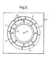
- a vibrating structure gyroscope includes a substantially planar vibratory resonator 1 having a substantially ring or hoop-like shape structure with inner and outer peripheries 2 and 3 respectively extending around a common axis 4.
- the gyroscope includes electromagnetic drive means as will be hereinafter described for causing the resonator to vibrate and electromagnetic sensing means, as will be hereinafter described in more detail, for sensing movement of the resonator 1.
- support means including a plurality of flexible support beams 5 for supporting the resonator 1 and for allowing it to vibrate in response to the electromagnetic drive means in a substantially undamped oscillation mode, such as to permit the resonator 1 to move relative to the support means in response to turning rate.
- the support beams 5 and resonator 1 are made from silicon.
- the support means also includes a frame 6 which is substantially rigid, surrounds the resonator 1 and is coupled to the outer periphery 3 of the ring or hoop-like shaped structure 1 by the support beams 5 which extend between the support frame 6 and the resonator 1.
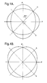
- the gyroscope has eight equi angularly spaced support beams 5 which represents the optimum preferred number.
- any irregularity or imperfection in the ring structure will give rise to a mismatch between the carrier and response mode frequencies which will degrade the performance of the gyroscope.
- a single support beam attached to the ring resonator will therefore differentially shift the carrier and response mode frequencies.
- eight identical support beams evenly spaced around the ring circumference will have an identical affect on the carrier and response modes and will not therefore generate a frequency split. This will be true for any feature with the same periodicity. It is thus advantageous to use eight support beams 5 spaced evenly around the ring resonator 1.
- the electromagnetic drive and the electromagnetic sensing means include metal tracks on the resonator 1 and on the support beams 5, together with means for generating or providing a magnetic field substantially perpendicularly to the plane of the vibratory resonator 1.
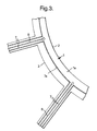
- each support beam 5 is provided with three laterally spaced tracks namely two outermost tracks 7 and an innermost central track 8 as can be seen best from the cross sectional view through a support beam 5 as illustrated in Figures 3 and 6
- the tracks extend externally along the length of each support beam 5 and are connected at their outermost ends with respect to the resonator 1 to bond pads 9 as seen in Figure 1.
- the two tracks 7 at their innermost ends extend in opposite directions around an outer substantially planar surface 1a of the resonator 1 over a segment thereof, as shown in Figure 3, and connect at their innermost ends to a respective one of the tracks 7 on the immediately adjacent support beam 5 with the number of segments corresponding to the number of support beams 5.
- two tracks 7 on adjacent support beams 5 together define an interconnecting segmental track section 7a on the outer substantially planar surface 1a of the resonator 1 as can be seen from Figure 3.
- the tracks 7 and 8 are made of metal and may be produced using standard evaporation and patterning techniques used in the silicon wafer processing industry.
- the centre track 8 extends onto the resonator 1 and terminates thereon adjacent the junction of the support beam 5 and resonator 1 as can be seen in Figure 3, to provide a means for minimising electrostatic coupling between the other two tracks 7 on the support beam 5.
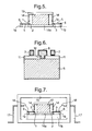
- a silicon oxide layer 11 is provided on the outer substantially planar surface la of the resonator 1 and support beams 5 as can best be seen from Figure 6, between the tracks 7, 8 and the silicon of the support beams 5 and resonator 1.
- the layer 11 insulates the tracks 7 and 8 from the silicon but connecting points such as 12 are provided through the silicon oxide layer 11 at appropriate positions connecting the centre track 8 to the silicon of the beam 5 to reduce unwanted capacitive signal coupling between adjacent tracks 7.
- the entire track system lies on top of the silicon oxide layer 11 which isolates the tracks from the silicon substrate which is conductive.
- the layout of the track pattern shown in Figure 3 and Figure 4 minimises any inductive coupling between tracks but it is to be understood that any other suitable arrangements of the tracks may be utilised as desired.
- the ideal number of support beams for the resonator 1 is eight.
- the tracks 7, 8 are made of any suitable metal such as aluminium or gold and means are provided for passing current through an appropriate segment track 7 and 7a to provide drive for the resonator 1.
- the sensing means is such as to detect vibration of the resonator 1 by detecting a voltage generated across an appropriate segment track 7, 7a as it moves in the perpendicular magnetic field.
- the means for generating or providing the magnetic field includes a magnet 13 and ring pole means 14 for concentrating the magnetic field on the ring or hoop-like area of the resonator 1.
- the poles 14, 14a and the magnet 13 form a magnetic circuit which concentrates a perpendicular magnetic field in the region of the ring resonator 1.
- the parameters within the magnetic circuit are chosen so as to set the operating point of the magnet at or near to its maximum energy condition, which thermally stabilises the magnet. At the same time the circuit parameters are chosen so as to maximise the field in the gap between the poles, in the region of the ring resonator, while maintaining achievable assembly tolerances.
- the magnetic material is chosen to be Samarium Cobalt (Sm 2 Co 17 ), which provides a high field intensity while having a low thermal sensitivity compared to other materials such as iron based magnets.
- the magnetic circuit also serves to load the magnet 13 to its ideal state so that it is thermally stabilised.
- the electromagnetic sensing or pick-off means requires motion perpendicular to the magnetic field to develop a signal, it is insensitive to vibration parallel to the magnetic field and thus avoids sensitivity to unwanted vibrations perpendicular to the plane of the device.
- the ring pole means 14 preferably comprises magnetically soft pole pieces with a further portion 14 a being provided underneath the ring or hoop-like shape structure area of the resonator 1 as can best be seen from Figures 5 and 7 of the accompanying drawings.
- the electromagnetic sensing means and the magnetic components 13, 14, 14 a are preferably sealed in a housing 15 to produce a board mountable gyro which can function as an angular rate sensor.
- the housing 15 preferably is hermetically sealed and conveniently made from a kovar hybrid material.
- Kovar is a magnetic material and hence a non-magnetic spacer 16 is provided between the housing 15 and the silicon/magnetic parts of the gyroscope. In this way the gyroscope of the invention is rendered substantially insensitive to applied external magnetic fields.
- External connection pins 17 are provided through the housing 15 and linked in any convenient manner to the bond pads 9 such as by wire pigtail bonds 18.
- the external rigid support frame 6 is mounted via a support pedestal 19 on the spacer 16.
- the support pedestal 19 may be of Silicon, bonded using Silicon wafer fusion bonding techniques.
- the pedestal 19 may be of glass, bonded using anodic bonding techniques. The glass should be chosen closely to match the thermal expansion coefficient of the Silicon support means.
Landscapes
- Physics & Mathematics (AREA)
- Engineering & Computer Science (AREA)
- General Physics & Mathematics (AREA)
- Radar, Positioning & Navigation (AREA)
- Remote Sensing (AREA)
- Gyroscopes (AREA)
Applications Claiming Priority (2)
| Application Number | Priority Date | Filing Date | Title |
|---|---|---|---|
| GB9703357 | 1997-02-18 | ||
| GB9703357A GB2322196B (en) | 1997-02-18 | 1997-02-18 | A vibrating structure gyroscope |
Publications (3)
| Publication Number | Publication Date |
|---|---|
| EP0859219A2 true EP0859219A2 (de) | 1998-08-19 |
| EP0859219A3 EP0859219A3 (de) | 2000-05-24 |
| EP0859219B1 EP0859219B1 (de) | 2005-01-26 |
Family
ID=10807878
Family Applications (1)
| Application Number | Title | Priority Date | Filing Date |
|---|---|---|---|
| EP98301134A Expired - Lifetime EP0859219B1 (de) | 1997-02-18 | 1998-02-17 | Vibrationsstrukturkreisel |
Country Status (7)
| Country | Link |
|---|---|
| US (1) | US5932804A (de) |
| EP (1) | EP0859219B1 (de) |
| JP (1) | JP2872213B2 (de) |
| AT (1) | ATE288072T1 (de) |
| DE (1) | DE69828713T2 (de) |
| ES (1) | ES2232915T3 (de) |
| GB (1) | GB2322196B (de) |
Cited By (9)
| Publication number | Priority date | Publication date | Assignee | Title |
|---|---|---|---|---|
| AU750061B2 (en) * | 1998-08-11 | 2002-07-11 | Bae Systems Plc | An angular rate sensor |
| US6848305B2 (en) | 2001-09-14 | 2005-02-01 | Bae Systems Plc | Vibratory gyroscopic rate sensor |
| US6883374B2 (en) | 2001-09-14 | 2005-04-26 | Bae Systems Plc | Vibratory gyroscopic rate sensor |
| US6978674B2 (en) | 2001-09-14 | 2005-12-27 | Bae Systems Plc | Vibratory gyroscopic rate sensor |
| US7188524B2 (en) | 2002-06-28 | 2007-03-13 | Sumitomo Precision Products, Co., Ltd | Conductive element for a movable electric circuit and a vibration gyroscope |
| EP2163848A1 (de) * | 2008-07-12 | 2010-03-17 | Atlantic Inertial Systems Limited | Verbesserung an oder im Zusammenhang mit vibrierenden Strukturgyroskopen |
| WO2010007406A3 (en) * | 2008-07-12 | 2010-10-14 | Atlantic Inertial Systems Limited | Improvements in or relating to vibrating structure gyroscopes |
| EP1923667A3 (de) * | 1999-09-16 | 2011-10-19 | Watson Industries, Inc. | Gyroskop zur Erfassung hoher Q-Winkel-Raten |
| US10731986B2 (en) | 2014-10-27 | 2020-08-04 | Atlantic Inertial Systems Limited | Digital controlled VCO for vibrating structure gyroscope |
Families Citing this family (44)
| Publication number | Priority date | Publication date | Assignee | Title |
|---|---|---|---|---|
| FR2769086B1 (fr) * | 1997-09-30 | 1999-12-03 | Salaberry Bernard Lucien Charl | Gyrometre vibrant a excitation et detection electromagnetique |
| GB2335273B (en) * | 1998-03-14 | 2002-02-27 | British Aerospace | A two axis gyroscope |
| GB0227084D0 (en) * | 2002-11-20 | 2002-12-24 | Bae Systems Plc | Method and apparatus for measuring scalefactor variation in a vibrating structure gyroscope |
| JP4058379B2 (ja) | 2003-05-16 | 2008-03-05 | Tdk株式会社 | 角速度センサおよび角速度検出装置 |
| JP4058378B2 (ja) | 2003-05-16 | 2008-03-05 | Tdk株式会社 | 角速度センサおよび角速度検出装置 |
| DE602005018322D1 (de) * | 2004-02-04 | 2010-01-28 | Atlantic Inertial Systems Ltd | Verfahren zur verringerung des vorspannungsfehlers in einem kreisel mit vibrierender struktur |
| JP2006064539A (ja) * | 2004-08-26 | 2006-03-09 | Matsushita Electric Works Ltd | ジャイロセンサおよび角速度検出方法 |
| RU2296300C1 (ru) * | 2005-10-31 | 2007-03-27 | Общество с ограниченной ответственностью Научно-Производственная Компания "Оптолинк" | Интегрирующий микромеханический вибрационный гироскоп |
| RU2331845C1 (ru) * | 2007-02-21 | 2008-08-20 | Открытое акционерное общество "Раменское приборостроительное конструкторское бюро" | Вибрационный гироскоп |
| US7992438B2 (en) * | 2007-11-28 | 2011-08-09 | Chung Shan Institute Of Science And Technology, Armaments Bureau, M.N.D. | Multiaxial gyroscope |
| CN101910790A (zh) * | 2008-01-29 | 2010-12-08 | 住友精密工业株式会社 | 使用压电体膜的振动陀螺仪及其制造方法 |
| US8205495B2 (en) * | 2008-06-10 | 2012-06-26 | The Boeing Company | Systematic disc resonator gyroscope tuning |
| JP5523755B2 (ja) * | 2009-02-11 | 2014-06-18 | 住友精密工業株式会社 | 圧電体膜を用いた振動ジャイロ及びその製造方法 |
| US8664951B2 (en) * | 2009-03-30 | 2014-03-04 | Honeywell International Inc. | MEMS gyroscope magnetic sensitivity reduction |
| CN101957201B (zh) * | 2009-07-13 | 2012-10-03 | 上海丽恒光微电子科技有限公司 | 电容型mems陀螺仪及其制造方法 |
| JP5632842B2 (ja) * | 2009-07-27 | 2014-11-26 | 住友精密工業株式会社 | 圧電体膜を用いた振動ジャイロ |
| RU2413926C1 (ru) * | 2009-12-24 | 2011-03-10 | Государственное образовательное учреждение высшего профессионального образования Московский государственный институт электронной техники (технический университет) (МИЭТ) | Чувствительный элемент кольцевого микромеханического вибрационного гироскопа |
| GB201003539D0 (en) * | 2010-03-03 | 2010-04-21 | Silicon Sensing Systems Ltd | Sensor |
| GB201005875D0 (en) | 2010-04-08 | 2010-05-26 | Silicon Sensing Systems Ltd | Sensors |
| RU2423666C1 (ru) * | 2010-05-11 | 2011-07-10 | Открытое акционерное общество "Раменское приборостроительное конструкторское бюро" (ОАО "РПКБ") | Резонатор вибрационного гироскопа |
| RU2423667C1 (ru) * | 2010-05-11 | 2011-07-10 | Открытое акционерное общество "Раменское приборостроительное конструкторское бюро" (ОАО "РПКБ") | Чувствительный элемент вибрационного гироскопа |
| GB201008195D0 (en) | 2010-05-17 | 2010-06-30 | Silicon Sensing Systems Ltd | Sensor |
| GB201008526D0 (en) | 2010-05-21 | 2010-07-07 | Silicon Sensing Systems Ltd | Sensor |
| GB201015585D0 (en) | 2010-09-17 | 2010-10-27 | Atlantic Inertial Systems Ltd | Sensor |
| GB201200128D0 (en) | 2012-01-05 | 2012-02-15 | Atlantic Inertial Systems Ltd | Strain decoupled sensor |
| US20140026658A1 (en) * | 2012-07-27 | 2014-01-30 | Biao Zhang | Mems device and a method of using the same |
| US9448069B2 (en) | 2012-10-01 | 2016-09-20 | The Royal Institution For The Advancement Of Learning/Mcgill University | Microelectromechanical bulk acoustic wave devices and methods |
| RU2518379C1 (ru) * | 2012-11-26 | 2014-06-10 | Открытое акционерное общество "Раменское приборостроительное конструкторское бюро" | Вибрационный вакуумный микрогироскоп |
| GB201307773D0 (en) * | 2013-04-30 | 2013-06-12 | Atlantic Inertial Systems Ltd | MEMS sensors |
| GB201313389D0 (en) | 2013-07-26 | 2013-09-11 | Atlantic Inertial Systems Ltd | Signal processing |
| US10571267B1 (en) * | 2015-09-01 | 2020-02-25 | Hrl Laboratories, Llc | High stability angular sensor |
| CN106224480B (zh) * | 2016-08-08 | 2018-07-20 | 太原理工大学 | 一种基于四杆机构的大行程柔性旋转铰 |
| JP6571065B2 (ja) | 2016-12-08 | 2019-09-04 | 株式会社東芝 | 振動装置 |
| JP7258760B2 (ja) * | 2017-09-21 | 2023-04-17 | 住友精密工業株式会社 | 角速度センサ |
| GB2567479B (en) | 2017-10-13 | 2022-04-06 | Atlantic Inertial Systems Ltd | Angular rate sensors |
| GB2570732B (en) | 2018-02-06 | 2023-01-11 | Atlantic Inertial Systems Ltd | Angular rate sensors |
| JP6787437B2 (ja) | 2018-05-08 | 2020-11-18 | 株式会社村田製作所 | ピエゾリングジャイロスコープ |
| US20210247186A1 (en) | 2018-05-08 | 2021-08-12 | Murata Manufacturing Co., Ltd. | Piezoelectric ring gyroscope |
| JP6769517B2 (ja) | 2018-05-08 | 2020-10-14 | 株式会社村田製作所 | ピエゾリングジャイロスコープ |
| CN109900262B (zh) * | 2019-04-08 | 2021-08-10 | 瑞声科技(新加坡)有限公司 | 陀螺仪 |
| CN110058041A (zh) * | 2019-04-08 | 2019-07-26 | 瑞声科技(新加坡)有限公司 | 陀螺仪 |
| GB2586081B (en) | 2019-08-02 | 2023-12-20 | Atlantic Inertial Systems Ltd | Signal processing |
| GB201911534D0 (en) | 2019-08-12 | 2019-09-25 | Atlantic Inertial Systems Ltd | Improved noise performance for vibrating structure gyroscopes |
| WO2021226993A1 (zh) * | 2020-05-15 | 2021-11-18 | 深圳市汇顶科技股份有限公司 | 一种陀螺仪及惯性传感器 |
Family Cites Families (8)
| Publication number | Priority date | Publication date | Assignee | Title |
|---|---|---|---|---|
| US3924475A (en) * | 1973-10-23 | 1975-12-09 | Singer Co | Vibrating ring gyro |
| GB8404668D0 (en) * | 1984-02-22 | 1984-03-28 | Burdess J S | Gyroscopic devices |
| US4644793A (en) * | 1984-09-07 | 1987-02-24 | The Marconi Company Limited | Vibrational gyroscope |
| US5060039A (en) * | 1988-01-13 | 1991-10-22 | The Charles Stark Draper Laboratory, Inc. | Permanent magnet force rebalance micro accelerometer |
| DE69102590T2 (de) * | 1990-05-18 | 1994-10-06 | British Aerospace | Trägheitssensoren. |
| US5203208A (en) * | 1991-04-29 | 1993-04-20 | The Charles Stark Draper Laboratory | Symmetrical micromechanical gyroscope |
| GB9207148D0 (en) * | 1992-04-01 | 1992-05-13 | British Aerospace | Planar rate sensor |
| US5696323A (en) * | 1996-06-25 | 1997-12-09 | Alliedsignal, Inc. | Two bar resonant beam Coriolis rate sensor |
-
1997
- 1997-02-18 GB GB9703357A patent/GB2322196B/en not_active Expired - Fee Related
-
1998
- 1998-02-10 US US09/021,306 patent/US5932804A/en not_active Expired - Lifetime
- 1998-02-17 AT AT98301134T patent/ATE288072T1/de not_active IP Right Cessation
- 1998-02-17 DE DE69828713T patent/DE69828713T2/de not_active Expired - Lifetime
- 1998-02-17 ES ES98301134T patent/ES2232915T3/es not_active Expired - Lifetime
- 1998-02-17 EP EP98301134A patent/EP0859219B1/de not_active Expired - Lifetime
- 1998-02-18 JP JP10036455A patent/JP2872213B2/ja not_active Expired - Lifetime
Cited By (13)
| Publication number | Priority date | Publication date | Assignee | Title |
|---|---|---|---|---|
| AU750061B2 (en) * | 1998-08-11 | 2002-07-11 | Bae Systems Plc | An angular rate sensor |
| USRE43755E1 (en) | 1999-09-16 | 2012-10-23 | Watson Industries, Inc. | High Q angular rate sensing gyroscope |
| EP1923667A3 (de) * | 1999-09-16 | 2011-10-19 | Watson Industries, Inc. | Gyroskop zur Erfassung hoher Q-Winkel-Raten |
| US6978674B2 (en) | 2001-09-14 | 2005-12-27 | Bae Systems Plc | Vibratory gyroscopic rate sensor |
| US6883374B2 (en) | 2001-09-14 | 2005-04-26 | Bae Systems Plc | Vibratory gyroscopic rate sensor |
| US6848305B2 (en) | 2001-09-14 | 2005-02-01 | Bae Systems Plc | Vibratory gyroscopic rate sensor |
| US7188524B2 (en) | 2002-06-28 | 2007-03-13 | Sumitomo Precision Products, Co., Ltd | Conductive element for a movable electric circuit and a vibration gyroscope |
| EP2163848A1 (de) * | 2008-07-12 | 2010-03-17 | Atlantic Inertial Systems Limited | Verbesserung an oder im Zusammenhang mit vibrierenden Strukturgyroskopen |
| WO2010007406A3 (en) * | 2008-07-12 | 2010-10-14 | Atlantic Inertial Systems Limited | Improvements in or relating to vibrating structure gyroscopes |
| CN102089620A (zh) * | 2008-07-12 | 2011-06-08 | 大西洋惯性系统有限公司 | 振动结构陀螺仪的或者涉及振动结构陀螺仪的改进 |
| US8555717B2 (en) | 2008-07-12 | 2013-10-15 | Atlantic Inertial Systems Limited | Vibrating structure gyroscopes |
| CN102089620B (zh) * | 2008-07-12 | 2014-01-08 | 大西洋惯性系统有限公司 | 振动结构陀螺仪的或者涉及振动结构陀螺仪的改进 |
| US10731986B2 (en) | 2014-10-27 | 2020-08-04 | Atlantic Inertial Systems Limited | Digital controlled VCO for vibrating structure gyroscope |
Also Published As
| Publication number | Publication date |
|---|---|
| US5932804A (en) | 1999-08-03 |
| GB2322196A (en) | 1998-08-19 |
| EP0859219B1 (de) | 2005-01-26 |
| JPH10267667A (ja) | 1998-10-09 |
| GB9703357D0 (en) | 1997-04-09 |
| ES2232915T3 (es) | 2005-06-01 |
| DE69828713D1 (de) | 2005-03-03 |
| EP0859219A3 (de) | 2000-05-24 |
| JP2872213B2 (ja) | 1999-03-17 |
| GB2322196B (en) | 2000-10-18 |
| ATE288072T1 (de) | 2005-02-15 |
| DE69828713T2 (de) | 2005-06-30 |
Similar Documents
| Publication | Publication Date | Title |
|---|---|---|
| EP0859219B1 (de) | Vibrationsstrukturkreisel | |
| US6282958B1 (en) | Angular rate sensor | |
| CA2217683C (en) | A rate sensor for sensing a rate on at least two and preferably three axes | |
| US6343509B1 (en) | Gyroscope | |
| US6289733B1 (en) | Planar vibratory gyroscopes | |
| JP3839720B2 (ja) | 角速度センサデバイスに関する改良 | |
| KR20040031087A (ko) | 진동형 자이로스코프식 속도 센서 | |
| EP1064519B1 (de) | Zweiachsiger kreisel | |
| US20040118204A1 (en) | Vibratory gyroscopic rate sensor | |
| US12507595B2 (en) | Quadrature bias error reduction for vibrating structure gyroscopes | |
| CA2458590A1 (en) | Vibratory gyroscopic rate sensor | |
| JPH0778430B2 (ja) | サニヤツク干渉計による回転速度の測定方法及び装置 | |
| JPH0464409B2 (de) |
Legal Events
| Date | Code | Title | Description |
|---|---|---|---|
| PUAI | Public reference made under article 153(3) epc to a published international application that has entered the european phase |
Free format text: ORIGINAL CODE: 0009012 |
|
| AK | Designated contracting states |
Kind code of ref document: A2 Designated state(s): AT BE CH DE DK ES FR GB IT LI NL SE |
|
| AX | Request for extension of the european patent |
Free format text: AL;LT;LV;MK;RO;SI |
|
| PUAL | Search report despatched |
Free format text: ORIGINAL CODE: 0009013 |
|
| AK | Designated contracting states |
Kind code of ref document: A3 Designated state(s): AT BE CH DE DK ES FI FR GB GR IE IT LI LU MC NL PT SE |
|
| AX | Request for extension of the european patent |
Free format text: AL;LT;LV;MK;RO;SI |
|
| RAP1 | Party data changed (applicant data changed or rights of an application transferred) |
Owner name: BAE SYSTEMS PLC |
|
| 17P | Request for examination filed |
Effective date: 20001107 |
|
| AKX | Designation fees paid |
Free format text: AT BE CH DE DK ES FR GB IT LI NL SE |
|
| 17Q | First examination report despatched |
Effective date: 20040527 |
|
| GRAP | Despatch of communication of intention to grant a patent |
Free format text: ORIGINAL CODE: EPIDOSNIGR1 |
|
| GRAS | Grant fee paid |
Free format text: ORIGINAL CODE: EPIDOSNIGR3 |
|
| GRAA | (expected) grant |
Free format text: ORIGINAL CODE: 0009210 |
|
| AK | Designated contracting states |
Kind code of ref document: B1 Designated state(s): AT BE CH DE DK ES FR GB IT LI NL SE |
|
| PG25 | Lapsed in a contracting state [announced via postgrant information from national office to epo] |
Ref country code: NL Free format text: LAPSE BECAUSE OF FAILURE TO SUBMIT A TRANSLATION OF THE DESCRIPTION OR TO PAY THE FEE WITHIN THE PRESCRIBED TIME-LIMIT Effective date: 20050126 Ref country code: LI Free format text: LAPSE BECAUSE OF FAILURE TO SUBMIT A TRANSLATION OF THE DESCRIPTION OR TO PAY THE FEE WITHIN THE PRESCRIBED TIME-LIMIT Effective date: 20050126 Ref country code: CH Free format text: LAPSE BECAUSE OF FAILURE TO SUBMIT A TRANSLATION OF THE DESCRIPTION OR TO PAY THE FEE WITHIN THE PRESCRIBED TIME-LIMIT Effective date: 20050126 Ref country code: BE Free format text: LAPSE BECAUSE OF FAILURE TO SUBMIT A TRANSLATION OF THE DESCRIPTION OR TO PAY THE FEE WITHIN THE PRESCRIBED TIME-LIMIT Effective date: 20050126 Ref country code: AT Free format text: LAPSE BECAUSE OF FAILURE TO SUBMIT A TRANSLATION OF THE DESCRIPTION OR TO PAY THE FEE WITHIN THE PRESCRIBED TIME-LIMIT Effective date: 20050126 |
|
| REG | Reference to a national code |
Ref country code: GB Ref legal event code: FG4D |
|
| REG | Reference to a national code |
Ref country code: CH Ref legal event code: EP |
|
| REG | Reference to a national code |
Ref country code: SE Ref legal event code: TRGR |
|
| PGFP | Annual fee paid to national office [announced via postgrant information from national office to epo] |
Ref country code: ES Payment date: 20050209 Year of fee payment: 8 |
|
| REF | Corresponds to: |
Ref document number: 69828713 Country of ref document: DE Date of ref document: 20050303 Kind code of ref document: P |
|
| PG25 | Lapsed in a contracting state [announced via postgrant information from national office to epo] |
Ref country code: DK Free format text: LAPSE BECAUSE OF FAILURE TO SUBMIT A TRANSLATION OF THE DESCRIPTION OR TO PAY THE FEE WITHIN THE PRESCRIBED TIME-LIMIT Effective date: 20050426 |
|
| REG | Reference to a national code |
Ref country code: ES Ref legal event code: FG2A Ref document number: 2232915 Country of ref document: ES Kind code of ref document: T3 |
|
| NLV1 | Nl: lapsed or annulled due to failure to fulfill the requirements of art. 29p and 29m of the patents act | ||
| REG | Reference to a national code |
Ref country code: CH Ref legal event code: PL |
|
| PLBE | No opposition filed within time limit |
Free format text: ORIGINAL CODE: 0009261 |
|
| STAA | Information on the status of an ep patent application or granted ep patent |
Free format text: STATUS: NO OPPOSITION FILED WITHIN TIME LIMIT |
|
| ET | Fr: translation filed | ||
| 26N | No opposition filed |
Effective date: 20051027 |
|
| PG25 | Lapsed in a contracting state [announced via postgrant information from national office to epo] |
Ref country code: ES Free format text: LAPSE BECAUSE OF NON-PAYMENT OF DUE FEES Effective date: 20060218 |
|
| REG | Reference to a national code |
Ref country code: ES Ref legal event code: FD2A Effective date: 20060218 |
|
| REG | Reference to a national code |
Ref country code: GB Ref legal event code: 732E |
|
| REG | Reference to a national code |
Ref country code: FR Ref legal event code: TP |
|
| PGFP | Annual fee paid to national office [announced via postgrant information from national office to epo] |
Ref country code: IT Payment date: 20120222 Year of fee payment: 15 |
|
| PGFP | Annual fee paid to national office [announced via postgrant information from national office to epo] |
Ref country code: SE Payment date: 20130212 Year of fee payment: 16 |
|
| REG | Reference to a national code |
Ref country code: SE Ref legal event code: EUG |
|
| PG25 | Lapsed in a contracting state [announced via postgrant information from national office to epo] |
Ref country code: SE Free format text: LAPSE BECAUSE OF NON-PAYMENT OF DUE FEES Effective date: 20140218 |
|
| REG | Reference to a national code |
Ref country code: FR Ref legal event code: PLFP Year of fee payment: 19 |
|
| PG25 | Lapsed in a contracting state [announced via postgrant information from national office to epo] |
Ref country code: IT Free format text: LAPSE BECAUSE OF NON-PAYMENT OF DUE FEES Effective date: 20140217 |
|
| REG | Reference to a national code |
Ref country code: FR Ref legal event code: PLFP Year of fee payment: 20 |
|
| PGFP | Annual fee paid to national office [announced via postgrant information from national office to epo] |
Ref country code: DE Payment date: 20170119 Year of fee payment: 20 Ref country code: FR Payment date: 20170124 Year of fee payment: 20 |
|
| PGFP | Annual fee paid to national office [announced via postgrant information from national office to epo] |
Ref country code: GB Payment date: 20170124 Year of fee payment: 20 |
|
| REG | Reference to a national code |
Ref country code: DE Ref legal event code: R071 Ref document number: 69828713 Country of ref document: DE |
|
| REG | Reference to a national code |
Ref country code: GB Ref legal event code: PE20 Expiry date: 20180216 |
|
| PG25 | Lapsed in a contracting state [announced via postgrant information from national office to epo] |
Ref country code: GB Free format text: LAPSE BECAUSE OF EXPIRATION OF PROTECTION Effective date: 20180216 |