EP0859225A2 - Procédé et dispositif de mesure du taux de réflexion d'éléments à fibre optique - Google Patents
Procédé et dispositif de mesure du taux de réflexion d'éléments à fibre optique Download PDFInfo
- Publication number
- EP0859225A2 EP0859225A2 EP98102478A EP98102478A EP0859225A2 EP 0859225 A2 EP0859225 A2 EP 0859225A2 EP 98102478 A EP98102478 A EP 98102478A EP 98102478 A EP98102478 A EP 98102478A EP 0859225 A2 EP0859225 A2 EP 0859225A2
- Authority
- EP
- European Patent Office
- Prior art keywords
- radiation
- optical fibre
- source
- fibre component
- component
- Prior art date
- Legal status (The legal status is an assumption and is not a legal conclusion. Google has not performed a legal analysis and makes no representation as to the accuracy of the status listed.)
- Withdrawn
Links
Images
Classifications
-
- G—PHYSICS
- G01—MEASURING; TESTING
- G01M—TESTING STATIC OR DYNAMIC BALANCE OF MACHINES OR STRUCTURES; TESTING OF STRUCTURES OR APPARATUS, NOT OTHERWISE PROVIDED FOR
- G01M11/00—Testing of optical apparatus; Testing structures by optical methods not otherwise provided for
Definitions
- optical fibre component denotes both all-fibre components, or integrated optics or discrete optics components equipped with an optical fibre termination for insertion into an optical fibre signal transmission line.
- the object of the invention is to provide a new measurement technique based on the re-injection into the laser cavity of the laser radiation which is reflected back from the optical fibre component under test, and on the coherent interaction, in the same cavity, of the reflected radiation with the oscillation field present in the cavity. In this way, all optical components external to the source and the related alignment procedures are eliminated, and a continuous wave laser diode can be used instead of a pulsed one.
- a radiation of predetermined wavelength is sent toward an optical fibre component under test, the fraction of radiation reflected by the optical fibre component is made to interact in the source with the radiation generated by the source itself, the radiation resulting from such interaction is detected and the electrical signal resulting from the detection is processed; the method further comprises the steps of: subjecting both the direct radiation and the reflected radiation to a phase modulation, such as to cause periodic variations of the optical path of said radiations, and, for said processing, of measuring the amplitude of a frequency component of said electrical signal at the frequency imposed by the phase modulation, such amplitude being linked to the value of the return losses through a factor which depends on said optical path variations, and deriving the value of the return losses through a comparison with the amplitude values of said electrical signal measured in a calibration phase wherein the direct radiation and the reflected radiation are subjected to calibrated attenuations.
- a phase modulation such as to cause periodic variations of the optical path of said radiations
- the condition for operation is that ⁇ be small (e. g. less than 1 %).
- the invention also provides a device to perform the method, comprising a source sending a radiation towards an optical fibre component under test and a photodiode, located on the side of the source opposite to that from which the radiation is sent towards the optical fibre component, to collect and detect a radiation resulting from the interaction between the radiation generated by the source and the radiation reflected by the optical fibre component, the photodiode being associated to means for processing an electrical signal resulting from the detection;
- the device also comprises a phase modulator inserted between the source and the optical fibre component under test to modulate in phase both the radiation sent towards the optical fibre component and the reflected one and to cause a periodic variation of the optical path of said radiations, and the means for processing said electrical signal are arranged to provide the amplitude value of a frequency component of the detected signal at the frequency imposed by the phase modulator.
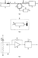
- a radiation source 11 comprising a commercial single-mode semiconductor laser of the Fabry-Perot or distributed reflector type sends a radiation of a wavelength ⁇ into a fibre length 19 through end face 13 submitted to anti-reflection treatment.
- a photodiode 12 is located behind laser 11, on support 10 thereof, and is arranged to detect the laser emission from the rear mirror.
- sources with powers within a very wide range e. g. 0.1 - 10 mW
- sources with powers within a very wide range e. g. 0.1 - 10 mW
- the wavelength there are no specific constraints for the wavelength, either, and it is possible to employ for instance semiconductor lasers for wavelengths between 600 and 2900 nm: clearly, in the case of measurements on optical telecommunications system components, the wavelengths to be employed are those typically used in such systems, for instance 850, 1300 and 1550 nanometres.
- a limited line width is important, particularly a width lower than 100 MHz, to guarantee an adequate time coherence.
- Fibre length 19 is wound for 5 - 10 turns, as indicated in 18, onto a phase modulator 14 conveniently comprising a piezoceramic tube (e. g. of lead zirconate-titanate or the like).
- Piezoceramic modulators are well known in the art.
- Modulator 14 is driven by a generator 110 of saw-tooth or triangular ramp waveforms such as to induce by piezoelectric effect a periodic optical path variation ⁇ L of at least 20 times the wavelength.
- waveforms with a frequency ranging for instance between 10 Hz and 1 kHz are suitable.
- This phase modulation has the purpose of giving rise, at the output of photodiode 12, to a periodic signal which just allows distinguishing the effect due to the reflection by the optical fibre component from the effects due to reflections by the other optical components of the system, resulting in a d.c. signal.
- An additional single fibre turn 15 can be used to control the polarisation state.
- Fibre length 19 ends with an angled surface 16, complementary to the shape of the end surface of a fibre length 20 for connection of fibre 19 to the device under test 17. Said connection is accomplished in conventional manner, by means of a physical contact connector or through a fusion splice. The angled termination aids in limiting the reflections at the interface between fibre lengths 19, 20, and thus in reducing the d.c. component in the signal detected by photodiode 12.
- Photodiode 12 is associated to a processing circuit (shown in Figure 3) which allows obtaining the return loss ⁇ from the amplitude ⁇ 1 ⁇ 2 cos2ks of the radiation detected by the photodiode itself.
- This amplitude shall vary periodically at the frequency imposed by the phase modulator, given by 2 ⁇ L/ ⁇ T, where ⁇ L is the optical path variation (clearly linked to s ) introduced by the phase modulator during ramp period T and ⁇ is the wavelength of the laser.
- an RC network 32 performs a low-pass filtering of the current generated by photodiode 12; RC network 32 is followed by a transimpedance converter 33, 34 and by a conventional lock-in amplifier 35 which performs the measurement of the amplitude of the electrical signal component at the frequency imposed by the phase modulator.
- Lock-in amplifier 35 receives as a reference the driving ramp of the phase modulator, provided by generator 110 ( Figure 1) through a connection 111. The value of ⁇ is obtained by comparison with the values plotted in a calibration curve obtained in an appropriate calibration phase.
- calibration unit 22 shown in Figure 2 is connected to fibre length 19 instead of optical fibre component 17 under test.
- the calibration unit contains a conventional calibrated attenuator 23, equipped with fibre terminations like that still denoted by 20, and a mirror 25. This unit yields a return loss equal to A 2 R, where A is the attenuation of calibrated attenuator 23 and R the reflectivity of mirror 25.
- the calibration curve is obtained by plotting the set attenuation values and the corresponding values of the output signal from the processing electronics associated to photodiode 12.
- the instrument just described can measure the return losses at more than one wavelength, by simply using multiple laser diodes, one for each wavelength of interest.
- optical fibre component 17 under test is also accessible, it will be possible to measure the insertion loss as well.
Landscapes
- Chemical & Material Sciences (AREA)
- Analytical Chemistry (AREA)
- Physics & Mathematics (AREA)
- General Physics & Mathematics (AREA)
- Testing Of Optical Devices Or Fibers (AREA)
- Light Guides In General And Applications Therefor (AREA)
- Instruments For Measurement Of Length By Optical Means (AREA)
- Investigating Or Analysing Materials By Optical Means (AREA)
- Manufacture, Treatment Of Glass Fibers (AREA)
- Geophysics And Detection Of Objects (AREA)
Applications Claiming Priority (2)
| Application Number | Priority Date | Filing Date | Title |
|---|---|---|---|
| IT97TO000126A IT1291028B1 (it) | 1997-02-14 | 1997-02-14 | Procedimento e dispositivo per la misura delle perdite di ritorno in componenti a fibra ottica. |
| ITTO970126 | 1997-02-14 |
Publications (2)
| Publication Number | Publication Date |
|---|---|
| EP0859225A2 true EP0859225A2 (fr) | 1998-08-19 |
| EP0859225A3 EP0859225A3 (fr) | 1999-05-12 |
Family
ID=11415374
Family Applications (1)
| Application Number | Title | Priority Date | Filing Date |
|---|---|---|---|
| EP98102478A Withdrawn EP0859225A3 (fr) | 1997-02-14 | 1998-02-13 | Procédé et dispositif de mesure du taux de réflexion d'éléments à fibre optique |
Country Status (5)
| Country | Link |
|---|---|
| US (1) | US5864400A (fr) |
| EP (1) | EP0859225A3 (fr) |
| JP (1) | JP2923770B2 (fr) |
| DE (1) | DE859225T1 (fr) |
| IT (1) | IT1291028B1 (fr) |
Cited By (2)
| Publication number | Priority date | Publication date | Assignee | Title |
|---|---|---|---|---|
| WO2007057050A1 (fr) * | 2005-11-15 | 2007-05-24 | Agilent Technologies, Inc. | Cavite externe destinee a generer un signal de stimulus et a filtrer le signal de reponse recu d’un dispositif a l'essai |
| CN109781389A (zh) * | 2019-04-01 | 2019-05-21 | 太原理工大学 | 基于二维光学微腔混沌激光器的高精度光纤故障检测装置 |
Families Citing this family (3)
| Publication number | Priority date | Publication date | Assignee | Title |
|---|---|---|---|---|
| US6744495B2 (en) * | 2002-08-22 | 2004-06-01 | Hon Hai Precision Ind. Co., Ltd. | WDM measurement system |
| US6879387B2 (en) * | 2003-04-04 | 2005-04-12 | Agilent Technologies, Inc. | Polarization dependent return loss measurement |
| CN112945369B (zh) * | 2021-01-29 | 2022-09-13 | 中国电力科学研究院有限公司 | 用于分布式光纤声音传感系统的环境仿真测试系统及方法 |
Family Cites Families (4)
| Publication number | Priority date | Publication date | Assignee | Title |
|---|---|---|---|---|
| JPS59225330A (ja) * | 1983-06-07 | 1984-12-18 | Fujitsu Ltd | フアイバ破断点検出方式 |
| FR2582800B1 (fr) * | 1985-05-30 | 1987-07-17 | Thomson Csf | Dispositif interferometrique en anneau a fibre optique monomode |
| WO1992019930A1 (fr) * | 1991-04-29 | 1992-11-12 | Massachusetts Institute Of Technology | Procede et appareil d'imagerie optique et de mesure |
| KR100217714B1 (ko) * | 1993-12-31 | 1999-09-01 | 윤종용 | 레이저 다이오드가 결합된 간섭형 광온도 센싱 시스템 |
-
1997
- 1997-02-14 IT IT97TO000126A patent/IT1291028B1/it active IP Right Grant
-
1998
- 1998-01-22 US US09/010,903 patent/US5864400A/en not_active Expired - Fee Related
- 1998-02-10 JP JP10042959A patent/JP2923770B2/ja not_active Expired - Fee Related
- 1998-02-13 EP EP98102478A patent/EP0859225A3/fr not_active Withdrawn
- 1998-02-13 DE DE0859225T patent/DE859225T1/de active Pending
Cited By (2)
| Publication number | Priority date | Publication date | Assignee | Title |
|---|---|---|---|---|
| WO2007057050A1 (fr) * | 2005-11-15 | 2007-05-24 | Agilent Technologies, Inc. | Cavite externe destinee a generer un signal de stimulus et a filtrer le signal de reponse recu d’un dispositif a l'essai |
| CN109781389A (zh) * | 2019-04-01 | 2019-05-21 | 太原理工大学 | 基于二维光学微腔混沌激光器的高精度光纤故障检测装置 |
Also Published As
| Publication number | Publication date |
|---|---|
| ITTO970126A1 (it) | 1998-08-14 |
| DE859225T1 (de) | 1999-11-04 |
| US5864400A (en) | 1999-01-26 |
| JP2923770B2 (ja) | 1999-07-26 |
| JPH10232316A (ja) | 1998-09-02 |
| EP0859225A3 (fr) | 1999-05-12 |
| IT1291028B1 (it) | 1998-12-14 |
Similar Documents
| Publication | Publication Date | Title |
|---|---|---|
| KR100419825B1 (ko) | 레이저광원장치,otdr장치및광통신라인감시장치 | |
| CA2571515C (fr) | Capteur a fibre optique distribuee | |
| JP3335205B2 (ja) | 光学システムの較正方法 | |
| US6122043A (en) | Method and apparatus for electrically reducing coherence/polarization noise in reflectometers | |
| Lees et al. | Advances in optical fiber distributed temperature sensing using the Landau-Placzek ratio | |
| US4796996A (en) | Laser temperature modulation and detection method | |
| EP0859225A2 (fr) | Procédé et dispositif de mesure du taux de réflexion d'éléments à fibre optique | |
| US5003268A (en) | Optical signal sampling apparatus | |
| US6055043A (en) | Method and apparatus for using phase modulation to reduce coherence/polarization noise in reflectometers | |
| US5747793A (en) | Variable light source compensated optical fiber sensing system | |
| US5543912A (en) | Reflectometry of an optical waveguide using a low coherence reflectometer | |
| JP3180746B2 (ja) | 光増幅装置並びに光増幅器利得制御方法及び装置 | |
| CA2229423C (fr) | Methode et dispositif pour mesurer les pertes par reflection dans les composants a fibres optiques | |
| Takahashi et al. | Underwater acoustic sensor using optical fiber Bragg grating as detecting element | |
| US5923414A (en) | Method and apparatus for thermally reducing coherence/polarization noise in reflectometers | |
| US5872624A (en) | Method and apparatus for retroreflectively reducing coherence/polarization noise in reflectometers | |
| CN118311336A (zh) | 基于法布里-珀罗结构的光学电场传感器 | |
| JP2626099B2 (ja) | 光伝送線路測定器 | |
| Jungerman et al. | Frequency domain optical network analysis using integrated optics | |
| JPH0522216B2 (fr) | ||
| US6034522A (en) | Fibre optic transducer incorporating an extraneous factor compensation referencing system | |
| EP4425726A1 (fr) | Appareil laser et procédé de commande de la largeur de ligne du faisceau laser émis | |
| WO1997046870A9 (fr) | Reduction du bruit de coherence dans des reflectometres | |
| WO1997046870A1 (fr) | Reduction du bruit de coherence dans des reflectometres | |
| RU2214584C1 (ru) | Оптический бриллюэновский рефлектометр |
Legal Events
| Date | Code | Title | Description |
|---|---|---|---|
| PUAI | Public reference made under article 153(3) epc to a published international application that has entered the european phase |
Free format text: ORIGINAL CODE: 0009012 |
|
| AK | Designated contracting states |
Kind code of ref document: A2 Designated state(s): DE FR GB IT NL SE |
|
| AX | Request for extension of the european patent |
Free format text: AL;LT;LV;MK;RO;SI |
|
| PUAL | Search report despatched |
Free format text: ORIGINAL CODE: 0009013 |
|
| AK | Designated contracting states |
Kind code of ref document: A3 Designated state(s): AT BE CH DE DK ES FI FR GB GR IE IT LI LU MC NL PT SE |
|
| AX | Request for extension of the european patent |
Free format text: AL;LT;LV;MK;RO;SI |
|
| EL | Fr: translation of claims filed | ||
| 17P | Request for examination filed |
Effective date: 19990709 |
|
| TCNL | Nl: translation of patent claims filed | ||
| DET | De: translation of patent claims | ||
| AKX | Designation fees paid |
Free format text: DE FR GB IT NL |
|
| RBV | Designated contracting states (corrected) |
Designated state(s): DE FR GB IT NL SE |
|
| RAP1 | Party data changed (applicant data changed or rights of an application transferred) |
Owner name: OTC OPTICAL TECHNOLOGIES CENTER S.R.L. |
|
| RAP1 | Party data changed (applicant data changed or rights of an application transferred) |
Owner name: AGILENT TECHNOLOGIES, INC., A CORPORATION OF THE S |
|
| RAP1 | Party data changed (applicant data changed or rights of an application transferred) |
Owner name: AGILENT TECHNOLOGIES INC. |
|
| RAP1 | Party data changed (applicant data changed or rights of an application transferred) |
Owner name: AGILENT TECHNOLOGIES INC. A DELAWARE CORPORATION |
|
| RAP1 | Party data changed (applicant data changed or rights of an application transferred) |
Owner name: AGILENT TECHNOLOGIES, INC. (A DELAWARE CORPORATION |
|
| STAA | Information on the status of an ep patent application or granted ep patent |
Free format text: STATUS: THE APPLICATION HAS BEEN WITHDRAWN |
|
| 18W | Application withdrawn |
Effective date: 20031202 |