EP0859247A2 - Fibre à dispersion décalée - Google Patents
Fibre à dispersion décalée Download PDFInfo
- Publication number
- EP0859247A2 EP0859247A2 EP98102419A EP98102419A EP0859247A2 EP 0859247 A2 EP0859247 A2 EP 0859247A2 EP 98102419 A EP98102419 A EP 98102419A EP 98102419 A EP98102419 A EP 98102419A EP 0859247 A2 EP0859247 A2 EP 0859247A2
- Authority
- EP
- European Patent Office
- Prior art keywords
- dispersion
- core
- refractive index
- shifted fiber
- cladding
- Prior art date
- Legal status (The legal status is an assumption and is not a legal conclusion. Google has not performed a legal analysis and makes no representation as to the accuracy of the status listed.)
- Ceased
Links
- 239000000835 fiber Substances 0.000 title claims abstract description 149
- 239000006185 dispersion Substances 0.000 claims abstract description 88
- 230000003287 optical effect Effects 0.000 claims abstract description 83
- 238000005253 cladding Methods 0.000 claims description 115
- 230000005672 electromagnetic field Effects 0.000 claims description 18
- 230000001902 propagating effect Effects 0.000 claims description 6
- 230000005540 biological transmission Effects 0.000 abstract description 27
- 239000013307 optical fiber Substances 0.000 description 32
- 230000000994 depressogenic effect Effects 0.000 description 28
- 230000007423 decrease Effects 0.000 description 12
- 230000000694 effects Effects 0.000 description 6
- 238000002156 mixing Methods 0.000 description 6
- 230000000052 comparative effect Effects 0.000 description 5
- 230000001965 increasing effect Effects 0.000 description 5
- 238000005452 bending Methods 0.000 description 4
- 238000004891 communication Methods 0.000 description 4
- 230000005684 electric field Effects 0.000 description 4
- VYPSYNLAJGMNEJ-UHFFFAOYSA-N Silicium dioxide Chemical compound O=[Si]=O VYPSYNLAJGMNEJ-UHFFFAOYSA-N 0.000 description 3
- 230000002195 synergetic effect Effects 0.000 description 3
- 238000013459 approach Methods 0.000 description 2
- 230000002349 favourable effect Effects 0.000 description 2
- 239000011521 glass Substances 0.000 description 2
- 238000005259 measurement Methods 0.000 description 2
- 238000012986 modification Methods 0.000 description 2
- 230000004048 modification Effects 0.000 description 2
- 230000010287 polarization Effects 0.000 description 2
- 230000000452 restraining effect Effects 0.000 description 2
- 238000004904 shortening Methods 0.000 description 2
- 235000012239 silicon dioxide Nutrition 0.000 description 2
- PXGOKWXKJXAPGV-UHFFFAOYSA-N Fluorine Chemical compound FF PXGOKWXKJXAPGV-UHFFFAOYSA-N 0.000 description 1
- 239000000470 constituent Substances 0.000 description 1
- 238000012937 correction Methods 0.000 description 1
- 230000003247 decreasing effect Effects 0.000 description 1
- 230000002542 deteriorative effect Effects 0.000 description 1
- 230000002708 enhancing effect Effects 0.000 description 1
- 229910052731 fluorine Inorganic materials 0.000 description 1
- 239000011737 fluorine Substances 0.000 description 1
- YBMRDBCBODYGJE-UHFFFAOYSA-N germanium oxide Inorganic materials O=[Ge]=O YBMRDBCBODYGJE-UHFFFAOYSA-N 0.000 description 1
- PVADDRMAFCOOPC-UHFFFAOYSA-N oxogermanium Chemical compound [Ge]=O PVADDRMAFCOOPC-UHFFFAOYSA-N 0.000 description 1
- 230000000644 propagated effect Effects 0.000 description 1
- 230000008054 signal transmission Effects 0.000 description 1
- 238000004804 winding Methods 0.000 description 1
Images






Classifications
-
- G—PHYSICS
- G02—OPTICS
- G02B—OPTICAL ELEMENTS, SYSTEMS OR APPARATUS
- G02B6/00—Light guides; Structural details of arrangements comprising light guides and other optical elements, e.g. couplings
- G02B6/02—Optical fibres with cladding with or without a coating
- G02B6/02004—Optical fibres with cladding with or without a coating characterised by the core effective area or mode field radius
- G02B6/02009—Large effective area or mode field radius, e.g. to reduce nonlinear effects in single mode fibres
- G02B6/02014—Effective area greater than 60 square microns in the C band, i.e. 1530-1565 nm
-
- G—PHYSICS
- G02—OPTICS
- G02B—OPTICAL ELEMENTS, SYSTEMS OR APPARATUS
- G02B6/00—Light guides; Structural details of arrangements comprising light guides and other optical elements, e.g. couplings
- G02B6/02—Optical fibres with cladding with or without a coating
- G02B6/02214—Optical fibres with cladding with or without a coating tailored to obtain the desired dispersion, e.g. dispersion shifted, dispersion flattened
- G02B6/02219—Characterised by the wavelength dispersion properties in the silica low loss window around 1550 nm, i.e. S, C, L and U bands from 1460-1675 nm
- G02B6/02228—Dispersion flattened fibres, i.e. having a low dispersion variation over an extended wavelength range
- G02B6/02238—Low dispersion slope fibres
- G02B6/02242—Low dispersion slope fibres having a dispersion slope <0.06 ps/km/nm2
-
- G—PHYSICS
- G02—OPTICS
- G02B—OPTICAL ELEMENTS, SYSTEMS OR APPARATUS
- G02B6/00—Light guides; Structural details of arrangements comprising light guides and other optical elements, e.g. couplings
- G02B6/02—Optical fibres with cladding with or without a coating
- G02B6/036—Optical fibres with cladding with or without a coating core or cladding comprising multiple layers
- G02B6/03605—Highest refractive index not on central axis
- G02B6/03611—Highest index adjacent to central axis region, e.g. annular core, coaxial ring, centreline depression affecting waveguiding
-
- G—PHYSICS
- G02—OPTICS
- G02B—OPTICAL ELEMENTS, SYSTEMS OR APPARATUS
- G02B6/00—Light guides; Structural details of arrangements comprising light guides and other optical elements, e.g. couplings
- G02B6/02—Optical fibres with cladding with or without a coating
- G02B6/036—Optical fibres with cladding with or without a coating core or cladding comprising multiple layers
- G02B6/03616—Optical fibres characterised both by the number of different refractive index layers around the central core segment, i.e. around the innermost high index core layer, and their relative refractive index difference
- G02B6/03622—Optical fibres characterised both by the number of different refractive index layers around the central core segment, i.e. around the innermost high index core layer, and their relative refractive index difference having 2 layers only
- G02B6/03627—Optical fibres characterised both by the number of different refractive index layers around the central core segment, i.e. around the innermost high index core layer, and their relative refractive index difference having 2 layers only arranged - +
-
- G—PHYSICS
- G02—OPTICS
- G02B—OPTICAL ELEMENTS, SYSTEMS OR APPARATUS
- G02B6/00—Light guides; Structural details of arrangements comprising light guides and other optical elements, e.g. couplings
- G02B6/02—Optical fibres with cladding with or without a coating
- G02B6/036—Optical fibres with cladding with or without a coating core or cladding comprising multiple layers
- G02B6/03616—Optical fibres characterised both by the number of different refractive index layers around the central core segment, i.e. around the innermost high index core layer, and their relative refractive index difference
- G02B6/03638—Optical fibres characterised both by the number of different refractive index layers around the central core segment, i.e. around the innermost high index core layer, and their relative refractive index difference having 3 layers only
- G02B6/03644—Optical fibres characterised both by the number of different refractive index layers around the central core segment, i.e. around the innermost high index core layer, and their relative refractive index difference having 3 layers only arranged - + -
Definitions
- the present invention relates to a single-mode optical fiber applied to a transmission line for optical communications or the like and, in particular, to a dispersion-shifted fiber suitable for wavelength division multiplexing (WDM) transmission.
- WDM wavelength division multiplexing
- the single-mode optical fiber applied to such a transmission line for light in the wavelength band of 1.55 ⁇ m (hereinafter referred to as 1.55- ⁇ m single-mode optical fiber) is designed so as to nullify its wavelength dispersion (phenomenon in which pulse wave broadens because the propagating speed of light varies depending on its wavelength) for light in the wavelength band of 1.55 ⁇ m (thus yielding a dispersion-shifted fiber having a zero-dispersion wavelength of 1.55 ⁇ m).
- a dispersion-shifted fiber for example, Japanese Patent Publication No.
- 3-18161 discloses a dispersion-shifted fiber having a refractive index profile of a dual-shape-core structure, whose core region is constituted by an inner core and an outer core having a refractive index lower than that of the inner core.
- Japanese Patent Application Laid-Open No. 63-43107 and Japanese Patent Application Laid-Open No. 2-141704 disclose a dispersion-shifted fiber having a refractive index profile of a depressed cladding/dual-shape-core structure, whose cladding region is constituted by an inner cladding and an outer cladding having a refractive index greater than that of the inner cladding.
- dispersion-shifted fibers employing a refractive index profile of the above-mentioned dual-shape-core structure or depressed cladding/dual-shape-core structure, whose zero-dispersion wavelength is shifted to the shorter wavelength side or longer wavelength side than the center wavelength of signal light (Japanese Patent Application Laid-Open No. 7-168046 and U.S. Patent No. 5,483,612).
- nonlinear optical effects refer to phenomena in which signal light pulses are distorted in proportion to density of light intensity or the like due to nonlinear phenomena such as four-wave mixing (FWM), self-phase modulation (SPM), cross-phase modulation (XPM), or the like. Transmission speed and relaying intervals in repeating transmission systems are restricted by the nonlinear optical effects.
- FWM four-wave mixing
- SPM self-phase modulation
- XPM cross-phase modulation
- Japanese Patent Application Laid-Open No. 8-248251 proposes an optical fiber having a configuration which suppresses the occurrence of the above-mentioned nonlinear optical phenomena, which may be generated when light having a high power is incident on the optical fiber, thereby reducing the distortion in optical signals caused by these nonlinear optical phenomena.
- Such an optical fiber has a refractive index profile whose effective core cross-sectional area A eff is designed to be greater than about 70 ⁇ m 2 .
- the effective core cross-sectional area A eff is given by the following expression (1):
- a eff 2 ⁇ 0 ⁇ E 2 rdr / 0 ⁇ E 4 rdr wherein E is an electric field accompanying propadated light, and r is a radial distance from the core center.
- dispersion slope is defined by the gradient of a graph indicating a dispersion characteristic in a predetermined wavelength band.
- dispersion slope increases as the effective core cross-sectional area A eff is greater
- no consideration has been made in the conventionally proposed dispersion-shifted fibers so as to optimize their dispersion slope value, which relates to the occurrences of distortion in signal light waveform due to dispersion and nonlinear optical effects, from the viewpoint of reducing distortion in the whole waveform.
- the dispersion-shifted fiber according to the present invention is a single-mode optical fiber for propagating signal light in a 1.55 ⁇ m wavelength band (namely, a wavelength in the range of 1,500 nm to 1,600 nm) comprising a core region extending along a predetermined reference axis and a cladding region disposed around the outer periphery of the core region.
- This dispersion-shifted fiber has a zero-dispersion wavelength shifted to a shorter wavelength side or longer wavelength side from the center wavelength (1,550 nm) of the 1.55- ⁇ m wavelength hand.
- the dispersion-shifted fiber according to the present invention has, at least, a dispersion whose absolute value is 1.0 to 4.5 ps/nm/km, a dispersion slope of 0.05 to 0.09 ps/nm 2 /km, an effective core cross-sectional area of at least 70 ⁇ m 2 , and a cutoff wavelength of at least 1,300 nm at a fiber length of 2 m.
- the inventors have found that, in the case where, at a wavelength of 1,550 nm, the absolute value of dispersion is 1.0 to 4.5 ps/nm/km and the effective core cross-sectional area is 70 ⁇ m 2 or greater, the total amount of distortion in signal light waveform can be reduced in a long-haul transmission if the dispersion slope is 0.05 to 0.09 ps/nm 2 /km.
- the total amount of distortion refers to the sum of the distortion in signal light waveform caused by the four-wave mixings and the distortions in signal light waveform caused by the synergistic effect of accumulated dispersion and self-phase modulation.
- the dispersion-shifted fiber according to the present invention can restrain the distortion from occurring due to the nonlinear optical effects, thereby allowing high-quality signal transmission to be realized.
- the core region is constituted by an inner core having a first refractive index, and an outer core disposed around the outer periphery of the inner core and having a second refractive index higher than the first refractive index; whereas a cladding region having a refractive index lower than the second refractive index is disposed around the outer periphery of the outer core. It means that this dispersion-shifted fiber can be suitably realized by a single-mode optical fiber having a refractive index profile of a ring-shaped core structure.
- a dispersion-shifted fiber having a refractive index profile of a ring-shaped core structure by changing its core diameter (outside diameter of the outer core) while keeping the ratio between the outside diameter of the inner core and the outside diameter of the outer core constant, the inventors have found the following facts. Namely, within a range where the core diameter is small, the greater is the core diameter, the smaller becomes the effective core cross-sectional area A eff . Within a range where the core diameter is considerably large, by contrast, the effective core cross-sectional area A eff increases together with the core diameter. It means that there are two core diameter values yielding the same effective core cross-sectional area A eff in a dispersion-shifted fiber having a refractive index profile of a ring-shaped core structure.
- the dispersion slope changes as well. Namely, within a range where the core diameter is small, in response to increase in core diameter, the dispersion slope as well as the effective core cross-sectional area A eff decreases. Within a range where the core diameter is considerably large, by contrast, while the effective core cross-sectional area A eff increases in response to increase in the core diameter, the dispersion slope decreases. It means that, in the dispersion-shifted fiber having a refractive index profile of a ring-shaped core structure, there is a region of core diameter where the dispersion slope decreases in response to increase in the effective core cross-sectional area A eff .
- a desired dispersion slope value can be appropriately selected from two different dispersion slope values, thus making it easy to realize the dispersion-shifted fiber according to the present invention.
- both effective core Cross-sectional area A eff and MFD decrease as the core diameter increases.
- the MFD decreases, whereas the effective core cross-sectional area A eff increases.
- the ratio between the outside diameter of the inner core and the outside diameter of the outer core is kept constant. In general, bending loss becomes smaller as the MFD is smaller and the cutoff wavelength is longer. From this viewpoint, the larger the diameter of the core is, the more advantageous it becomes.
- this dispersion-shifted fiber satisfies the following relationship: ⁇ n 1 - ⁇ n 2 ⁇ 1% wherein ⁇ n 1 is a relative refractive index difference or the outer core with respect to the cladding region, and ⁇ n 2 is a relative refractive index difference of the inner core with respect to the cladding region.
- ⁇ n 1 is a relative refractive index difference or the outer core with respect to the cladding region
- ⁇ n 2 is a relative refractive index difference of the inner core with respect to the cladding region.
- ⁇ n 2 is effective in shortening cutoff wavelength. Accordingly, taking account of short-haul light transmission, in order to yield a cutoff wavelength of 1,550 nm or less at a fiber length of 2 m, it is necessary for ⁇ n 2 to be not greater than -0.4%.
- the cladding region can have a unitary structure (hereinafter referred to as matched cladding structure), it can also be constituted by an inner cladding disposed around the outer periphery of the outer core and having a third refractive index lower than the second refractive index (refractive index of the outer core), and an outer cladding disposed around the outer periphery of the inner cladding and having a fourth refractive index higher than the third refractive index.
- the dispersion-shifted fiber can have a refractive index profile of a depressed cladding/ring-shaped core structure (double structure).
- the depressed cladding Structure Since the dispersion-shifted fiber having a depressed cladding structure has an effect to decrease undesired 2-mode light, as compared with the dispersion-shifted fiber having a matched cladding structure without a depression, the depressed cladding Structure is effective to make a cutoff wavelength of 2-mode light become short.
- the inner cladding has an appropriate outer diameter to the outer core, and it is preferable that the dispersion-shifted fiber having a refractive index profile of a depressed cladding/ring-shaped core structure satisfies the following relationship: 1.2 ⁇ 2c/2b ⁇ 2.2.
- ⁇ n 1 is a relative refractive index difference of the outer core with respect to the outer cladding
- ⁇ n 2 is a relative refractive index difference of the inner core with respect to the outer cladding.
- its cutoff wavelength becomes shorter than that of a dispersion-shifted fiber having a refractive index profile of a simple ring-shaped core structure with no depressed cladding structure, even when the values of relative refractive index differences ⁇ n 1 and ⁇ n 2 in the former are the same as those in the latter.
- the optical power distribution (or electromagnetic field distribution) is maximized at the core center of the optical fiber.
- the conventional optical fiber is provided with another segment (outer core) disposed outside the center segment (inner core).
- the optical fiber of the above-mentioned Japanese Patent Application Laid-Open No. 8-248251 which is designed so as to enlarge the effective core cross-sectional area A eff , may be problematic in that bending loss increases as the effective core cross-sectional area A eff becomes larger.
- the dispersion-shifted fiber according to the present invention has, at least, a refractive index profile of a ring-shaped core structure, thereby, in a cross section perpendicular to a wave-guiding direction of signal light, the part where the optical power distribution in the fundamental mode of signal light or its accompanying electromagnetic field distribution is maximized is radially separated from the center of the core region by a predetermined distance.
- an optical fiber having a refractive index profile of a ring-shaped core structure when the outside diameter of its inner core is small, it does not yield a large difference in terms of the optical power distribution of propagated light or its accompanying electromagnetic field distribution as compared with an optical fiber having a refractive index profile other than that of the ring-shaped core structure. Namely, even in the optical fiber having a refractive index profile of a ring-shaped core structure, when the outside diameter of the inner core is small, the part where the optical power distribution of signal light in the fundamental mode or electromagnetic field distribution is maximized becomes to substantially overlap with the center of the core region. In such a state, the characteristic of the refractive index profile with a ring-shaped core structure can not fully be exhibited.
- the part where the optical power distribution of signal light in a fundamental mode or its accompanying electromagnetic field distribution is maximized is radially separated from the center of the core region by about 0.5 ⁇ m to about 5 ⁇ m.
- the dispersion-shifted fiber according to the present invention satisfies a relationship of: P 1 > 1.2 ⁇ P 0 wherein P 0 is an optical power of signal light in the fundamental mode at the center of the core region or an intensity of its accompanying electromagnetic field, and P 1 is a maximum value, in a radial direction from the center of the core region, of optical power distribution of signal light in the fundamental mode or its accompanying electromagnetic field distribution.
- the effective core cross-sectional area A eff can be made greater, thereby the nonlinear optical phenomena can be reduced without increasing bending loss.
- the dispersion-shifted fiber according to the present invention is a dispersion-shifted fiber whose zero-dispersion wavelength is shifted from the center wavelength (1,550 nm) of the above-mentioned 1.55- ⁇ m wavelength band by a predetermined amount.
- the effective core cross-sectional area A eff is enlarged while the zero-dispersion wavelength is shifted, signals can be more effectively restrained from deteriorating due to four-wave mixing.
- Fig. 1 is a view showing a cross-sectional structure of a dispersion-shifted fiber according to a first embodiment of the present invention and its refractive index profile in a diameter direction.
- this dispersion-shifted fiber 100 is a single-mode optical fiber mainly composed of silica glass for propagating signal light in a wavelength band of 1.55 ⁇ m (1,500 to 1,600 nm), comprising an inner core 111 having an outside diameter of 2a and a refractive index of n 1 ; an outer core 112 disposed around the outer periphery of the inner core 111 and having an outside diameter of 2b (i.e., diameter of a core region 110 is 2b) and a refractive index of n 2 (> n 1 ); and a cladding region 210 disposed around the outer periphery of the outer core 112, having a refractive index of n 3 ( ⁇ n 2 ).
- the core region 110 is constituted by the inner core 111 and the outer
- the dispersion-shifted fiber 100 is set such that, as characteristics at a wavelength of 1,550 nm, its absolute value of dispersion is within the range of 1.0 to 4.5 ps/nm/km, dispersion slope is within the range of 0.05 to 0.09 ps/nm 2 /km, effective core cross-sectional area is at least 70 ⁇ m 2 , and cutoff wavelength at 2 m length is at least 1,300 nm.
- the cutoff wavelength is 2,510 nm, thus failing to guarantee single-mode propagation of signal light in the 1.55- ⁇ m band at a fiber length of 2 m. Nevertheless, since the cutoff wavelength becomes shorter as the transmission distance increases, the cutoff wavelength becomes shorter than the wavelength of signal light in the case of long-haul transmission such as that on the order of 1,000 km, thus leaving no problem in practice (allowing single-mode propagation to he guaranteed).
- Fig. 2 is a graph showing changes in effective core cross-sectional area A eff and MFD when the core diameter 2b (corresponding to outside diameter of the outer core 112) is changed.
- the relative refractive index difference ⁇ n 1 is 1.5%
- Fig. 3 is a graph showing changes in cutoff wavelength ⁇ c and dispersion slope at a fiber length of 2 m when the core diameter 2b (corresponding to outside diameter of the outer core 2b) is changed.
- the relative refractive index difference ⁇ n 1 is 1.5%
- the cutoff wavelength ⁇ c becomes longer as the core diameter 2b increases.
- the dispersion slope decreases within the range where the core diameter 2b is not greater than 4 ⁇ m, increases within the range where the core diameter 2b is greater than 4 ⁇ m and not greater than 7 ⁇ m, and decreases again within the range where the core diameter 2b is greater than 7 ⁇ m.
- a desired value of dispersion slope can be selected from two different dispersion slope values.
- Figs. 4 to 7 are views for explaining changes in bit error rate (BER) at 5 Gbps accompanying changes in dispersion slope.
- BER bit error rate
- the transmission distance of the dispersion-shifted fiber to be measured is set to 9,000 km, while optical fibers for dispersion compensation (in practice, single-mode optical fibers for the band of the 1.3- ⁇ m band, whose dispersion value at the center wavelength is 18 ps/nm/km) are inserted therein at intervals of 400 km in order to nullify accumulated dispersion at the center wavelength.
- the ordinate indicates Q value which is a value equivalent to bit error rate.
- Fig. 8 is a view for explaining the above-mentioned Q value.
- BER of 10 -9 or less in the above-mentioned transmission distance is a sufficient performance.
- the BER of 10 -9 or less is equivalent to a Q value of 15.7 dB or more.
- the Q value deteriorates more at center channels when the dispersion slope value is smaller, while it deteriorates more at longer wavelength regions when the dispersion slope value is greater. It seems to be because four-wave mixing is likely to occur at wavelengths in the vicinity of the center channel when the dispersion slope value is small; and because, as the dispersion value increases in a long-wavelength region such as channel numbers of 14 to 16 when the dispersion slope value is large, a synergistic effect of greatly accumulated dispersion and self-phase modulation is generated.
- the dispersion slope value where BER becomes 10 -9 or less is from 0.05 to 0.09 ps/nm 2 /km.
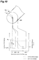
- Fig. 9 is a view for explaining an optical power distribution in the fundamental mode of signal light in the above-mentioned preferred example.
- the part where the optical power distribution in the fundamental mode of signal light(equivalent to the electromagnetic field distribution accompanying the propagation of signal light) is maximized is set at a position radially separated from the center of the core region 110.
- the optical fiber according to the comparative example comprises an inner core 191 having an outside diameter (2a) of 1.36 ⁇ m and a refractive index of n 1 ; an outer core 192 disposed around the outer periphery of the inner core 191 and having an outside diameter (2b) of 2.26 ⁇ m (i.e., diameter of a core region 190 is 2.26 ⁇ m) and a refractive index of n 2 (> n 1 ); and a cladding region 290 disposed around the outer periphery of the outer core 192 and having a refractive index of n 3 ( ⁇ n 2 ).
- the core region 190 is constituted by the inner core 191 and the outer core 192.
- the optical power distribution in the fundamental mode of signal light is maximized at the center of the core region 190.
- This optical fiber has a dispersion slope of 0.126 ps/nm 2 /km and thus cannot attain the above-mentioned favorable BER.
- the optical power distribution in the radial direction in the fundamental mode has a depression at the center part. Therefore, by positively adopting a refractive index profile which yields such a power distribution as shown in Fig. 6, a dispersion-shifted fiber having a large effective core cross-sectional area A eff and a small dispersion slope can be realized.
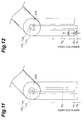
- the refractive index profile can also be such that, as shown in Fig. 11, the refractive index n 1 is greater than the refractive index n 3 .
- the refractive index profile can be such that refractive index n 1 is less than refractive index n 3 .
- the cutoff wavelength at 2 m length is 1,500 m, which is shorter than the wavelength of signal light in the 1.55- ⁇ m band, thus making it usable for short-haul transmission as well.
- Fig. 13 is a view showing a cross-sectional structure of a dispersion-shifted fiber according to a second embodiment of the present invention and its refractive index profile in a diameter direction.
- this dispersion-shifted fiber 200 is a single-mode optical fiber for propagating signal light in the 1.55- ⁇ m wavelength band and, in particular, has a refractive index profile 201 of a depressed cladding/ring-shaped core structure.
- the dispersion-shifted fiber 200 of the second embodiment comprises an inner core 121 having an outside diameter of 2a and a refractive index of n 1 ; an outer core 122 disposed around the outer periphery of the inner care 121 and having an outside diameter of 2b (i.e., diameter of a core region 120 is 2b) and a refractive index of n 2 (> n 1 ); an inner cladding 221 disposed around the outer periphery of the outer core 122 and having an outside diameter of 2c and a refractive index of n 3 ( ⁇ n 2 ); and an outer cladding 222 disposed around the outer periphery of the inner cladding 221 and having a refractive index of n 4 (> n 3 ).
- the core region 120 is constituted by the inner core 121 and the outer core 122, whereas a cladding region 220 is constituted by the inner cladding 221 and the outer cladding 222. Also, a refractive index profile 201 indicates refractive index at each part on line L2 in the drawing.
- the dispersion-shifted fiber 200 is set such that, as characteristics at a wavelength of 1,550 nm, its absolute value of dispersion is within the range of 1.0 to 4.5 ps/nm/km, dispersion slope is within the range of 0.05 to 0.09 ps/nm 2 /km, effective core cross-sectional area is at least 70 ⁇ m 2 , and cutoff wavelength at 2 m length is at least 1,300 nm.
- the core diameter 2b (outside diameter of the outer core 122) is 9 ⁇ m
- the outside diameter 2c of the inner cladding 221 is 18 ⁇ m; obtained at a wavelength of 1,550 nm are: dispersion (ps/nm/km) -2
- the cutoff wavelength is 1,702 nm, thus failing to guarantee single-mode propagation of signal light in the 1.55- ⁇ m band at 2 m length. Nevertheless, since the cutoff wavelength becomes shorter as the transmission distance increases, the cutoff wavelength becomes shorter than the wavelength of signal light in the case of long-haul transmission such as that on the order of 1,000 km, thus leaving no problem in practice.
- a dispersion-shifted fiber having a refractive index profile of a depressed cladding/ring-shaped core structure such as that of the second embodiment
- the effective core cross-sectional area A eff and MFD would change similarly to those in the first embodiment, i.e., as shown in Fig. 2.
- a desired dispersion slope value can be selected from two different dispersion slope values.
- the dispersion slope value at which BER becomes 10 -9 or less is from 0.05 to 0.09 ps/nm 2 /km.
- Fig. 14 is a view for explaining an optical power distribution of signal light in a fundamental mode in a preferred example of the second embodiment.
- Fig. 14 which is similar to Fig. 9, in a cross section perpendicular to the wave-guiding direction of the signal light, the part where the optical power distribution of signal light in the fundamental mode is maximized is set at a position radially shifted from the center of the core region 120.
- a dispersion-shifted fiber having a refractive index profile of a depressed cladding/ring-shaped core structure such as that of the second embodiment
- the relative refractive index difference ⁇ n 1 is 1.1%
- the relative refractive index difference ⁇ n 2 is -0.4%
- the optical power distribution in the fundamental mode of signal light in a cross section perpendicular to the wave-guiding direction of the signal light is maximized in the vicinity of the center of the core region, thereby its dispersion slope cannot attain the above-mentioned favorable BER.
- the optical power distribution in the radial direction in the fundamental mode has a depression at the center part.
- a refractive index yielding such an optical power distribution is positively utilized, a dispersion-shifted fiber having a large effective core cross-sectional area A eff and a small dispersion slope can be realized.
- the refractive index profile in which the refractive index n 1 of the inner core 121 is the same as the refractive index n 3 of the inner cladding 221, the refractive index profile can also be such that, as shown in Fig. 15, the refractive index n 1 is greater than the refractive index n 3 .
- the refractive index profile can be such that the refractive index n 1 is less than the refractive index n 3 .
- each of a width and a depth of a depression to be provided in the above refractive index profile should be set within an appropriate range.
- the width of depression corresponds to a thickness (c-b) of the inner cladding in a diameter direction of the fiber and the depth of depression corresponds to a relative refractive index difference of the inner cladding with respect to the outer cladding.
- the dispersion-shifted fiber having a refractive index profile of a depressed cladding structure has an effect to decrease undesired 2-mode light, as compared with the dispersion-shifted fiber having a matched cladding structure without a depression, it is effective to make a cutoff wavelength of 2-mode light become short.
- the inner cladding has an appropriate outer diameter to the outer core, and it is preferable that the dispersion-shifted fiber having a refractive index profile of a depressed cladding/ring-shaped core structure satisfies the following relationship: 1.2 ⁇ 2c/2b ⁇ 2.2. Additionally, in the dispersion-shifted fiber according to the present invention, it is necessary for the relative refractive index difference ⁇ n 1 of the outer core with respect to the cladding region (or outer cladding) and the relative refractive index difference ⁇ n 2 of the inner core with respect to the cladding region (or outer cladding) to satisfy the following relationship: ⁇ n 1 - ⁇ n 2 ⁇ 1%.
- the dispersion value of the dispersion-shifted fiber depends, in a refractive index profile in a diameter direction within its core region, on the amount of depression ( ⁇ n 1 - ⁇ n 2 ) of a depressed area corresponding to the core center region; in order to obtain a sufficient dispersion value, at least the amount of depression is required to be 1.0% or more.
- ⁇ n 2 decreases (or increasing the absolute value thereof when negative) the relative refractive index difference ⁇ n 2 of the inner core with respect to the cladding region (or outer cladding) is effective in shortening its cutoff wavelength. Accordingly, when short-haul optical transmission is taken into consideration, it is necessary for ⁇ n 2 to be -0.4% or smaller in order to attain a cutoff wavelength of 1,550 nm or shorter at 2 m length.
- ⁇ n 1 is the relative refractive index difference of the outer core with respect to the cladding region
- ⁇ n 2 is the relative refractive index difference of the inner core with respect to the cladding region.
- ⁇ n 1 is the relative refractive index difference of the outer core with respect to the outer cladding
- ⁇ n 2 is the relative refractive index difference of the inner core with respect to the outer cladding
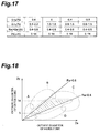
- the above relationships do not depend on the relative refractive index differences ⁇ n 1 and ⁇ n 2 .
- the above-mentioned various characteristics of the dispersion-shifted fiber cannot be obtained.
- the dispersion slope value becomes too large; (b) in the area indicated by B therein, the effective core cross-sectional area A eff becomes too large, and bending loss increases; (c) in the area indicated by C therein, the dispersion value becomes too large; and (d) in the area indicated by D therein, the effective core cross-sectional area A eff becomes too small.
- the dispersion-shifted fiber according to the present invention is set such that, as various characteristics at a wavelength of 1,550 nm, the absolute value of dispersion is within the range of 1.0 to 4.5 ps/nm/km, the effective core cross-sectional area A eff is at least 70 ⁇ m 2 , the cutoff wavelength at 2 m length is at least 1,300 nm, and the dispersion slope is within the range of 0.05 to 0.09 ps/nm 2 /km; it can realize high-quality long-haul optical transmission, while effectively restraining nonlinear optical effects from occurring.
- the dispersion-shifted fiber according to the present invention has a refractive index profile of a ring-shaped core structure (including a refractive index profile of a depressed cladding/ring-shaped core structure), the dispersion-shifted fiber having the above characteristics at the wavelength of 1550 nm can be realized favorably.
- the refractive index profile of the dispersion-shifted fiber according to the present invention is adjusted such that the position where the optical power distribution in the fundamental mode of signal light is maximized is radially separated from the center of the core region by a predetermined distance
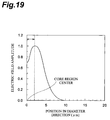
- the inventors prepared a plurality of optical fiber samples each having a form of electromagnetic field distribution (equivalent to the optical power distribution) which can be approximately regarded as a Gaussian distribution, while the position where the electromagnetic field distribution is maximised is separated from the center of the core region by a predetermined distance.
- Fig. 19 is a graph showing a typical example of electromagnetic field distribution in thus prepared plurality of optical fiber samples. In this graph, the electric field amplitude indicated in the ordinate is standardized with its maximum value taken as 1.
- Fig. 20 is a graph showing the dependence of MFD on distance
- Fig. 21 is a graph showing the dependence of loss caused by microbend on distance. As shown in Fig.
- MFD decreases as the distance increases, from which it has been confirmed that the dispersion-shifted fiber according to the present invention can reduce MFD while keeping an effective core cross-sectional area A eff equivalent to that in the conventional optical fiber.
- the dispersion-shifted fiber according to the present invention is designed such that the position where the optical power distribution of signal light in the fundamental mode is maximized is radially separated from the center of the core region by 0.5 ⁇ m to 5 ⁇ m.
- Fig. 22 shows results of measurement of various characteristics with respect to light having a wavelength of 1.55 ⁇ m (1,550 nm) in two samples each having a refractive index profile of a single-ring structure.
- the refractive indexes in each equation can be placed in random order, when the relative refractive index difference has a negative value, it means that the refractive index of the corresponding glass region is lower than that of the cladding region.
- the above-mentioned reference refractive index n cld is the refractive index of the outer cladding in the cladding region.
- the refractive index ⁇ N ⁇ of the medium is given by the sum of the normal value ⁇ N 0 ⁇ and an increase which is proportional te the square of optical electric field amplitude E.
- the constant of proportion ⁇ N 2 ⁇ (unit: m 2 /V 2 ) in the second term is called nonlinear refractive index.
- Fig. 23 is a graph showing a relationship between the refractive index profile of sample 1 shown in the table of Fig. 22 and its optical power along a radial direction from the center.
- the value of optical power is standardized with the maximum value taken as 1, and indicated as the optical power is its fundamental mode (LP01) and second-order mode (LP11).
- each of samples 1 and 2 has a single-ring structure, whereas germanium oxide is added to pure silica glass in the vicinity of the glass part (outer core) where the refractive index is maximized, which is disposed outside the core center (inner core), thus increasing the refractive index.
- pure silica glass is doped with fluorine, so that refractive index is lowered.
- the optical fiber of sample 1 yields an effective core cross-sectional area A eff of 87 ⁇ m 2 and an MFD of 11.2 ⁇ m, thus being capable of reducing the MFD by about 20% as compared with the conventional optical fiber having the equivalent effective core cross-sectional area A eff , which yields an MFD of about 13 ⁇ m.
- the inventors wound the dispersion-shifted fiber of sample 1 around a reel having a diameter of 280 mm and a surface provided with sandpaper, and measured fluctuations in loss before and after winding.
- the increase in loss of sample 1 with respect to light having a wavelength of 1.55 ⁇ m is 0.19 dB/km
- the conventional optical fiber yields an increase in loss of 1.12 dB/km, whereby the dispersion-shifted fiber of sample 1 can greatly reduce the increase in loss caused by microbend.
- the position yielding the maximum optical power with respect to light having a wavelength of 1.55 ⁇ m is separated from the core center by about 3 ⁇ m.
- sample 2 has an effective core cross-sectional area A eff of 86 ⁇ m 2 and an MFD of 11.0 ⁇ m.
- the cutoff wavelength ⁇ c at 2 m length in each of samples 1 and 2 is 1.7 ⁇ m, which is longer than the wavelength used (1.55- ⁇ m wavelength band)
- both samples would effectively function in a single mode under their normal state of usage, since the single mode is guaranteed at a fiber length of 100 m or more with respect to light having a wavelength of 1.55 ⁇ m.
- the wavelength dispersion value of sample 2 is -2.6 ps/mm/km. That is, the dispersion value at the wavelength used is not zero (zero-dispersion wavelength ⁇ 0 is shifted to the longer wavelength side than the used wavelength of 1.55 ⁇ m). Consequently, the occurrence of four-wave mixing, which causes signals in wavelength multiplexing transmission to deteriorate, is reduced.
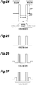
- each of the above-mentioned samples 1 and 2 has a refractive index profile of a single-ring structure in which the inner core has a refractive index lower than that of the cladding region as shown in Fig. 24, they should not be restricted to this refractive index profile.
- the refractive index profile applicable to the dispersion-shifted fiber according to the present invention may be, for example, a structure in which the refractive index of the inner core and that of the cladding region coincide with each other as shown in Fig. 25, a depressed ring structure shown in Fig. 26, or a double-ring structure shown in Fig. 27.
- the position where the optical power distribution of signal light in the fundamental mode is maximized is radially separated from the center of the core region by a predetermined distance, while, when the optical power in the fundamental mode of signal light at the center of the core region is P 0 and the maximum value of the optical power distribution in the fundamental mode is P 1 , the maximum value P 1 satisfies to be greater than the value of 1.2 times the optical power P 0 at the center of core region. Consequently, it can realize a structure in which the effective core cross-sectional area A eff can be increased while keeping the made field diameter (MFD) small.
- MFD field diameter
- the effective core cross-sectional area A eff can be efficiently enhanced.
- the refractive index profile of the dispersion-shifted fiber according to the present invention is designed such that desired values can be obtained as characteristics with respect to light at the center wavelength (1,550 nm) in the 1.55- ⁇ m wavelength band, it can effectively restrain nonlinear optical phenomena from occurring.
Landscapes
- Physics & Mathematics (AREA)
- Chemical & Material Sciences (AREA)
- Dispersion Chemistry (AREA)
- General Physics & Mathematics (AREA)
- Optics & Photonics (AREA)
- Optical Communication System (AREA)
Applications Claiming Priority (4)
| Application Number | Priority Date | Filing Date | Title |
|---|---|---|---|
| JP27975/97 | 1997-02-12 | ||
| JP2797597 | 1997-02-12 | ||
| JP179896/97 | 1997-07-04 | ||
| JP17989697 | 1997-07-04 |
Publications (2)
| Publication Number | Publication Date |
|---|---|
| EP0859247A2 true EP0859247A2 (fr) | 1998-08-19 |
| EP0859247A3 EP0859247A3 (fr) | 1999-04-07 |
Family
ID=26365988
Family Applications (1)
| Application Number | Title | Priority Date | Filing Date |
|---|---|---|---|
| EP98102419A Ceased EP0859247A3 (fr) | 1997-02-12 | 1998-02-12 | Fibre à dispersion décalée |
Country Status (8)
| Country | Link |
|---|---|
| US (1) | US6181858B1 (fr) |
| EP (1) | EP0859247A3 (fr) |
| KR (1) | KR100728452B1 (fr) |
| CN (1) | CN1105928C (fr) |
| AU (1) | AU736110B2 (fr) |
| CA (1) | CA2229280A1 (fr) |
| ID (1) | ID19879A (fr) |
| TW (1) | TW355224B (fr) |
Cited By (20)
| Publication number | Priority date | Publication date | Assignee | Title |
|---|---|---|---|---|
| EP0987568A1 (fr) * | 1998-09-17 | 2000-03-22 | Alcatel | Fibre optique monomode à dispersion décalée optimisée pour les hauts débits |
| WO2000017681A1 (fr) * | 1998-09-17 | 2000-03-30 | Alcatel | Fibre optique a rapport optimise entre l'aire effective et la pente de dispersion pour systemes de transmission a fibre optique a multiplexage en longueurs d'onde |
| FR2784197A1 (fr) * | 1998-10-05 | 2000-04-07 | Cit Alcatel | Fibre optique monomode a dispersion decalee a grande aire effective |
| WO2000037977A1 (fr) * | 1998-12-18 | 2000-06-29 | Pirelli Cavi E Sistemi S.P.A. | Fibre optique pour systemes de reseaux d'acces ou reseaux metropolitains |
| EP1030199A1 (fr) * | 1999-02-18 | 2000-08-23 | Alcatel | Fibre de ligne pour systèmes de transmission à fibre optique à multiplexage en longueurs d'onde |
| EP1030200A1 (fr) * | 1999-02-18 | 2000-08-23 | Alcatel | Fibre optique à grande surface effective et à forte dispersion chromatique |
| WO2000055661A1 (fr) * | 1999-03-12 | 2000-09-21 | Corning Incorporated | Fibre de guide d'onde a surface efficace importante |
| WO2000060389A1 (fr) * | 1999-03-31 | 2000-10-12 | Fujikura Ltd. | Fibre optique multimode a fonction de suppression du mode d'ordre superieur |
| WO2001004675A1 (fr) * | 1999-07-12 | 2001-01-18 | Fujikura Ltd. | Fibre optique a dispersion decalee |
| WO2001018575A1 (fr) * | 1999-09-09 | 2001-03-15 | Fujikura Ltd. | Fibre optique a dispersion decalee |
| WO2001065287A1 (fr) * | 2000-03-03 | 2001-09-07 | Pirelli Cavi E Sistemi S.P.A. | Fibre optique pour transmission mrl |
| WO2001042831A3 (fr) * | 1999-12-10 | 2001-12-13 | Blazephotonics Ltd | Ameliorations apportees a des fibres a cristal photonique et a des dispositifs a fibres a cristal photonique |
| US6343176B1 (en) | 1998-07-31 | 2002-01-29 | Corning Incorporated | Long haul single mode waveguide |
| US6599957B2 (en) | 2001-05-07 | 2003-07-29 | Corning Incorporated | Photosensitive material suitable for making waveguides and method of making waveguides utilizing this photosensitive optical material |
| US6694079B1 (en) | 1999-07-27 | 2004-02-17 | Fujikura Ltd. | Disperson-shifted optical fiber employing dual shape core profile |
| US6744951B2 (en) | 2001-05-07 | 2004-06-01 | Cornigg Incorporated | Waveguides and method of making them |
| EP1308755A3 (fr) * | 2001-10-29 | 2004-08-04 | Fujikura Ltd. | Fibre optique monomode et ligne optique composite |
| EP1020741A4 (fr) * | 1997-10-02 | 2005-12-21 | Sumitomo Electric Industries | Fibre optique a decalage et dispersion |
| US6990282B2 (en) | 1999-12-10 | 2006-01-24 | Crystal Fibre A/S | Photonic crystal fibers |
| US7027698B2 (en) | 2000-03-03 | 2006-04-11 | Pirelli Cavi E Sistemi S.P.A. | Optical fiber for WDM transmission |
Families Citing this family (28)
| Publication number | Priority date | Publication date | Assignee | Title |
|---|---|---|---|---|
| US6079494A (en) * | 1997-09-03 | 2000-06-27 | Halliburton Energy Services, Inc. | Methods of completing and producing a subterranean well and associated apparatus |
| JPH11218623A (ja) * | 1998-01-30 | 1999-08-10 | Shin Etsu Chem Co Ltd | ソリトンパルス圧縮用光ファイバおよびその製造方法 |
| AU773983B2 (en) * | 1998-12-17 | 2004-06-10 | Sumitomo Electric Industries, Ltd. | Optical fiber |
| EP1124145A1 (fr) * | 1999-08-20 | 2001-08-16 | The Furukawa Electric Co., Ltd. | Fibre optique et ligne de transmission optique comprenant cette derniere |
| RU2216755C2 (ru) * | 2000-02-25 | 2003-11-20 | Дзе Фурукава Электрик Ко., Лтд. | Оптическое волокно с низкой дисперсией и оптическая система передачи с использованием оптического волокна с низкой дисперсией |
| JP3784656B2 (ja) * | 2001-03-15 | 2006-06-14 | 株式会社フジクラ | 分散補償光ファイバおよびこれを用いた分散補償モジュールと光ファイバ複合伝送路 |
| US7155128B2 (en) * | 2001-12-14 | 2006-12-26 | Nortel Networks Limited | Decorrelation of WDM signals |
| US6856744B2 (en) * | 2002-02-13 | 2005-02-15 | The Furukawa Electric Co., Ltd. | Optical fiber and optical transmission line and optical communication system including such optical fiber |
| JP2004012685A (ja) * | 2002-06-05 | 2004-01-15 | Furukawa Electric Co Ltd:The | 正分散光ファイバ、それを用いた光伝送路 |
| KR20050026083A (ko) * | 2002-07-31 | 2005-03-14 | 코닝 인코포레이티드 | 넓은 유효 범위, 낮은 슬로프 및 낮은 영분산을 갖는 비영분산 천이 광섬유 |
| US7894697B2 (en) * | 2005-10-07 | 2011-02-22 | Sumitomo Electric Industries, Ltd. | Optical fiber, optical transmission line, optical module, and optical transmission system |
| FR2893149B1 (fr) * | 2005-11-10 | 2008-01-11 | Draka Comteq France | Fibre optique monomode. |
| FR2899693B1 (fr) * | 2006-04-10 | 2008-08-22 | Draka Comteq France | Fibre optique monomode. |
| US7620282B2 (en) * | 2006-08-31 | 2009-11-17 | Corning Incorporated | Low bend loss single mode optical fiber |
| JP5315601B2 (ja) * | 2006-09-12 | 2013-10-16 | 住友電気工業株式会社 | 光ファイバおよび光ファイバ型デバイス |
| DK2206001T3 (da) * | 2007-11-09 | 2014-07-07 | Draka Comteq Bv | Optisk fiber, der er modstandsdygtig over for mikrobøjning |
| US7778498B2 (en) * | 2008-02-12 | 2010-08-17 | Ofs Fitel Llc | Systems and techniques for generating cylindrical vector beams |
| FR2930997B1 (fr) * | 2008-05-06 | 2010-08-13 | Draka Comteq France Sa | Fibre optique monomode |
| US7773848B2 (en) | 2008-07-30 | 2010-08-10 | Corning Incorporated | Low bend loss single mode optical fiber |
| CN102122991B (zh) * | 2010-12-15 | 2013-10-23 | 江苏大学 | 一种光纤通信系统 |
| JP6361101B2 (ja) * | 2012-09-04 | 2018-07-25 | 住友電気工業株式会社 | 光ファイバ |
| CN103257393B (zh) * | 2012-10-30 | 2015-03-04 | 长飞光纤光缆股份有限公司 | 一种大有效面积光纤 |
| US9442246B2 (en) * | 2013-10-14 | 2016-09-13 | Futurewei Technologies, Inc. | System and method for optical fiber |
| JP2015197488A (ja) * | 2014-03-31 | 2015-11-09 | 富士通株式会社 | 光導波路、光電混載配線板、プリント基板ユニット及び光導波路製造方法 |
| WO2016061657A1 (fr) * | 2014-10-23 | 2016-04-28 | Coractive High-Tech Inc. | Ensemble fibre optique ayant un élément de formation de faisceau |
| JP6335949B2 (ja) * | 2016-02-12 | 2018-05-30 | 株式会社フジクラ | マルチコアファイバ |
| JP2019120894A (ja) * | 2018-01-11 | 2019-07-22 | 住友電気工業株式会社 | 光ファイバ、光ファイバ心線および光伝送システム |
| JP2019152811A (ja) * | 2018-03-06 | 2019-09-12 | 住友電気工業株式会社 | 光ファイバ、光ファイバ心線および光伝送システム |
Family Cites Families (17)
| Publication number | Priority date | Publication date | Assignee | Title |
|---|---|---|---|---|
| JPS51133041A (en) | 1975-05-14 | 1976-11-18 | Sumitomo Electric Ind Ltd | Light transmission fiber |
| JPS6252508A (ja) | 1985-09-02 | 1987-03-07 | Nippon Telegr & Teleph Corp <Ntt> | 光フアイバ |
| US4852968A (en) | 1986-08-08 | 1989-08-01 | American Telephone And Telegraph Company, At&T Bell Laboratories | Optical fiber comprising a refractive index trench |
| JP2831363B2 (ja) | 1988-11-22 | 1998-12-02 | 株式会社フジクラ | 光ファイバ |
| JPH0318161A (ja) | 1989-06-15 | 1991-01-25 | Toshiba Corp | 電話機 |
| US5327516A (en) | 1993-05-28 | 1994-07-05 | At&T Bell Laboratories | Optical fiber for wavelength division multiplexing |
| JPH07230015A (ja) * | 1994-02-17 | 1995-08-29 | Furukawa Electric Co Ltd:The | 分散シフト型シングルモード光ファイバと分散シフト型シングルモード光ファイバ用母材と分散シフト型シングルモード光ファイバ用母材の製造方法 |
| US5559921A (en) * | 1994-06-24 | 1996-09-24 | Sumitomo Electric Industries, Ltd. | Single mode optical fiber |
| FR2724234B1 (fr) | 1994-09-05 | 1997-01-03 | Alcatel Fibres Optiques | Fibre optique monomode a dispersion decalee |
| US5483612A (en) | 1994-10-17 | 1996-01-09 | Corning Incorporated | Increased capacity optical waveguide |
| US5553185A (en) | 1994-12-27 | 1996-09-03 | Corning Incorporated | Controlled dispersion optical waveguide |
| US5835655A (en) * | 1995-01-26 | 1998-11-10 | Corning Incorporated | Large effective area waveguide fiber |
| JPH08220362A (ja) | 1995-02-10 | 1996-08-30 | Fujikura Ltd | 分散シフト光ファイバ |
| FR2736440B1 (fr) | 1995-07-07 | 1997-08-01 | Alcatel Submarcom | Guide optique monomode a dispersion decalee et grande surface effective de mode |
| US5822488A (en) * | 1995-10-04 | 1998-10-13 | Sumitomo Electric Industries, Inc. | Single-mode optical fiber with plural core portions |
| TW342460B (en) * | 1996-01-16 | 1998-10-11 | Sumitomo Electric Industries | A dispersion shift fiber |
| US5781684A (en) * | 1996-12-20 | 1998-07-14 | Corning Incorporated | Single mode optical waveguide having large effective area |
-
1998
- 1998-02-11 CA CA002229280A patent/CA2229280A1/fr not_active Abandoned
- 1998-02-11 US US09/022,033 patent/US6181858B1/en not_active Expired - Lifetime
- 1998-02-11 TW TW087101837A patent/TW355224B/zh active
- 1998-02-12 KR KR1019980004148A patent/KR100728452B1/ko not_active Expired - Fee Related
- 1998-02-12 CN CN98106967A patent/CN1105928C/zh not_active Expired - Fee Related
- 1998-02-12 EP EP98102419A patent/EP0859247A3/fr not_active Ceased
- 1998-02-12 ID IDP980182A patent/ID19879A/id unknown
- 1998-02-12 AU AU53905/98A patent/AU736110B2/en not_active Ceased
Cited By (44)
| Publication number | Priority date | Publication date | Assignee | Title |
|---|---|---|---|---|
| EP1020741A4 (fr) * | 1997-10-02 | 2005-12-21 | Sumitomo Electric Industries | Fibre optique a decalage et dispersion |
| US6343176B1 (en) | 1998-07-31 | 2002-01-29 | Corning Incorporated | Long haul single mode waveguide |
| EP0987568A1 (fr) * | 1998-09-17 | 2000-03-22 | Alcatel | Fibre optique monomode à dispersion décalée optimisée pour les hauts débits |
| EP0987569A1 (fr) * | 1998-09-17 | 2000-03-22 | Alcatel | Fibre optique monomode à dispersion décalée optimisée pour les hauts débits |
| FR2783609A1 (fr) * | 1998-09-17 | 2000-03-24 | Cit Alcatel | Fibre optique monomode optimisee pour les hauts debits |
| WO2000017682A1 (fr) * | 1998-09-17 | 2000-03-30 | Alcatel | Fibre optique monomode a dispersion decalee optimisee pour les hauts debits |
| WO2000017681A1 (fr) * | 1998-09-17 | 2000-03-30 | Alcatel | Fibre optique a rapport optimise entre l'aire effective et la pente de dispersion pour systemes de transmission a fibre optique a multiplexage en longueurs d'onde |
| WO2000017683A1 (fr) * | 1998-09-17 | 2000-03-30 | Alcatel | Fibre optique monomode a dispersion decalee optimisee pour les hauts debits |
| US6424776B1 (en) | 1998-09-17 | 2002-07-23 | Alcatel | Monomode optical fiber with optimized dispersion shift for high speeds |
| US6535676B1 (en) | 1998-09-17 | 2003-03-18 | Alcatel | Optical fibre with optimized ratio of effective area to dispersion scope for optical fibre transmission system with wavelength multiplexing |
| US6625359B1 (en) | 1998-09-17 | 2003-09-23 | Alcatel | Dispersion-shifted single-mode optical fiber optimized for high data rates |
| WO2000020905A1 (fr) * | 1998-10-05 | 2000-04-13 | Alcatel | Fibre optique monomode a dispersion decalee a grande aire effective |
| CN1294432C (zh) * | 1998-10-05 | 2007-01-10 | 阿尔卡塔尔公司 | 大有效截面的色散位移单模光纤 |
| CN1869745B (zh) * | 1998-10-05 | 2010-09-08 | 阿尔卡塔尔公司 | 大有效截面的色散位移单模光纤 |
| EP0992817A1 (fr) * | 1998-10-05 | 2000-04-12 | Alcatel | Fibre optique monomode à dispersion décalée à grande aire effective |
| US6459839B1 (en) | 1998-10-05 | 2002-10-01 | Alcatel | Phase-shifted monomode optical fibre with large effective area |
| FR2784197A1 (fr) * | 1998-10-05 | 2000-04-07 | Cit Alcatel | Fibre optique monomode a dispersion decalee a grande aire effective |
| WO2000037977A1 (fr) * | 1998-12-18 | 2000-06-29 | Pirelli Cavi E Sistemi S.P.A. | Fibre optique pour systemes de reseaux d'acces ou reseaux metropolitains |
| US6577800B2 (en) | 1998-12-18 | 2003-06-10 | Pirelli Cavi E Sistemi S.P.A. | Optical fiber for metropolitan and access network systems |
| EP1030200A1 (fr) * | 1999-02-18 | 2000-08-23 | Alcatel | Fibre optique à grande surface effective et à forte dispersion chromatique |
| EP1030199A1 (fr) * | 1999-02-18 | 2000-08-23 | Alcatel | Fibre de ligne pour systèmes de transmission à fibre optique à multiplexage en longueurs d'onde |
| US6516123B1 (en) | 1999-02-18 | 2003-02-04 | Alcatel | Optical fiber with large effective core area and high chromatic dispersion |
| FR2790107A1 (fr) * | 1999-02-18 | 2000-08-25 | Cit Alcatel | Fibre de ligne pour systemes de transmission a fibre optique a multiplexage en longueurs d'onde |
| FR2790108A1 (fr) * | 1999-02-18 | 2000-08-25 | Cit Alcatel | Fibre optique a grande surface effective et a forte dispersion chromatique |
| WO2000055661A1 (fr) * | 1999-03-12 | 2000-09-21 | Corning Incorporated | Fibre de guide d'onde a surface efficace importante |
| US6535678B1 (en) | 1999-03-31 | 2003-03-18 | Fujikura Ltd | Multimode optical fiber with a higher order mode removing function |
| WO2000060389A1 (fr) * | 1999-03-31 | 2000-10-12 | Fujikura Ltd. | Fibre optique multimode a fonction de suppression du mode d'ordre superieur |
| RU2216756C2 (ru) * | 1999-07-12 | 2003-11-20 | Фудзикура Лтд. | Оптическое волокно со смещенной дисперсией |
| CN1302300C (zh) * | 1999-07-12 | 2007-02-28 | 株式会社藤仓 | 色散位移光纤 |
| WO2001004675A1 (fr) * | 1999-07-12 | 2001-01-18 | Fujikura Ltd. | Fibre optique a dispersion decalee |
| US6785453B1 (en) | 1999-07-12 | 2004-08-31 | Fujikura Ltd. | Dispersion shifted optical fiber |
| US6694079B1 (en) | 1999-07-27 | 2004-02-17 | Fujikura Ltd. | Disperson-shifted optical fiber employing dual shape core profile |
| RU2216029C2 (ru) * | 1999-09-09 | 2003-11-10 | Фудзикура Лтд. | Оптическое волокно с дисперсионным смещением |
| US6546177B1 (en) | 1999-09-09 | 2003-04-08 | Fujikura Ltd. | Dispersion shifted optical fiber |
| WO2001018575A1 (fr) * | 1999-09-09 | 2001-03-15 | Fujikura Ltd. | Fibre optique a dispersion decalee |
| WO2001042831A3 (fr) * | 1999-12-10 | 2001-12-13 | Blazephotonics Ltd | Ameliorations apportees a des fibres a cristal photonique et a des dispositifs a fibres a cristal photonique |
| US6853786B2 (en) | 1999-12-10 | 2005-02-08 | Crystal Fibre A/C | Photonic-crystal fibers and photonic-crystal fiber devices |
| US6990282B2 (en) | 1999-12-10 | 2006-01-24 | Crystal Fibre A/S | Photonic crystal fibers |
| US7027698B2 (en) | 2000-03-03 | 2006-04-11 | Pirelli Cavi E Sistemi S.P.A. | Optical fiber for WDM transmission |
| WO2001065287A1 (fr) * | 2000-03-03 | 2001-09-07 | Pirelli Cavi E Sistemi S.P.A. | Fibre optique pour transmission mrl |
| US6744951B2 (en) | 2001-05-07 | 2004-06-01 | Cornigg Incorporated | Waveguides and method of making them |
| US6599957B2 (en) | 2001-05-07 | 2003-07-29 | Corning Incorporated | Photosensitive material suitable for making waveguides and method of making waveguides utilizing this photosensitive optical material |
| EP1308755A3 (fr) * | 2001-10-29 | 2004-08-04 | Fujikura Ltd. | Fibre optique monomode et ligne optique composite |
| US6895140B2 (en) | 2001-10-29 | 2005-05-17 | Fujikura, Ltd. | Single-mode optical fiber and composite optical line |
Also Published As
| Publication number | Publication date |
|---|---|
| KR19980071289A (ko) | 1998-10-26 |
| KR100728452B1 (ko) | 2007-11-14 |
| HK1010916A1 (en) | 1999-07-02 |
| US6181858B1 (en) | 2001-01-30 |
| CN1194382A (zh) | 1998-09-30 |
| CN1105928C (zh) | 2003-04-16 |
| AU5390598A (en) | 1998-08-20 |
| ID19879A (id) | 1998-08-13 |
| EP0859247A3 (fr) | 1999-04-07 |
| CA2229280A1 (fr) | 1998-08-12 |
| AU736110B2 (en) | 2001-07-26 |
| TW355224B (en) | 1999-04-01 |
Similar Documents
| Publication | Publication Date | Title |
|---|---|---|
| US6181858B1 (en) | Dispersion-shifted fiber | |
| US6658190B2 (en) | Optical fiber and optical communication system including the same | |
| EP1054275B1 (fr) | Fibre optique a correction de dispersion et ligne de transmission optique comprenant ladite fibre optique | |
| US6169837B1 (en) | Dispersion-flattened optical fiber | |
| US6335995B1 (en) | Dispersion-shifted fiber | |
| US6445864B2 (en) | Dispersion compensating optical fiber | |
| JP4494691B2 (ja) | 光伝送路 | |
| US6859595B2 (en) | Optical fiber and optical transmission system including the same | |
| US6477306B2 (en) | Dispersion-compensating optical fiber, and, optical transmission line and dispersion-compensating module respectively including the same | |
| EP0862069A2 (fr) | Fibre optique | |
| US6614976B2 (en) | Optical fiber having a large positive dispersion | |
| US6496631B2 (en) | Optical transmission line and optical transmission system including the same | |
| US6466721B1 (en) | Dispersion compensating optical fiber and optical transmission line | |
| US6487353B2 (en) | Dispersion-shifted optical fiber | |
| EP0789257A1 (fr) | Fibre à dispersion décalée | |
| US6591048B2 (en) | Dispersion compensating optical fiber and optical transmission line using the optical fiber | |
| JPWO1999030193A1 (ja) | 分散フラット光ファイバ | |
| EP0949517A1 (fr) | Fibre a dispersion decalee | |
| JP2976959B2 (ja) | 分散シフトファイバ | |
| US6229946B1 (en) | Dispersion-shifted optical fiber | |
| JPWO1999032909A1 (ja) | 光伝送路 | |
| JPH10239550A (ja) | 分散シフトファイバ | |
| US6684017B1 (en) | Optical transmission line and optical transmission system including the same | |
| KR20000006257A (ko) | Wdm송수신을위한저비-선형도를갖는광섬유 | |
| AU4203701A (en) | Dispersion-shifted fiber |
Legal Events
| Date | Code | Title | Description |
|---|---|---|---|
| PUAI | Public reference made under article 153(3) epc to a published international application that has entered the european phase |
Free format text: ORIGINAL CODE: 0009012 |
|
| AK | Designated contracting states |
Kind code of ref document: A2 Designated state(s): DE FR GB IT SE |
|
| AX | Request for extension of the european patent |
Free format text: AL;LT;LV;MK;RO;SI |
|
| PUAL | Search report despatched |
Free format text: ORIGINAL CODE: 0009013 |
|
| RHK1 | Main classification (correction) |
Ipc: G02B 6/00 |
|
| AK | Designated contracting states |
Kind code of ref document: A3 Designated state(s): AT BE CH DE DK ES FI FR GB GR IE IT LI LU MC NL PT SE |
|
| AX | Request for extension of the european patent |
Free format text: AL;LT;LV;MK;RO;SI |
|
| 17P | Request for examination filed |
Effective date: 19990621 |
|
| 17Q | First examination report despatched |
Effective date: 19991015 |
|
| AKX | Designation fees paid |
Free format text: DE FR GB IT SE |
|
| STAA | Information on the status of an ep patent application or granted ep patent |
Free format text: STATUS: THE APPLICATION HAS BEEN REFUSED |
|
| 18R | Application refused |
Effective date: 20020323 |