EP0859266A2 - Source laser à plusieurs longueurs d'ondes - Google Patents
Source laser à plusieurs longueurs d'ondes Download PDFInfo
- Publication number
- EP0859266A2 EP0859266A2 EP98300749A EP98300749A EP0859266A2 EP 0859266 A2 EP0859266 A2 EP 0859266A2 EP 98300749 A EP98300749 A EP 98300749A EP 98300749 A EP98300749 A EP 98300749A EP 0859266 A2 EP0859266 A2 EP 0859266A2
- Authority
- EP
- European Patent Office
- Prior art keywords
- light
- wavelength
- output
- source
- optical modulator
- Prior art date
- Legal status (The legal status is an assumption and is not a legal conclusion. Google has not performed a legal analysis and makes no representation as to the accuracy of the status listed.)
- Granted
Links
Images


Classifications
-
- H—ELECTRICITY
- H04—ELECTRIC COMMUNICATION TECHNIQUE
- H04B—TRANSMISSION
- H04B10/00—Transmission systems employing electromagnetic waves other than radio-waves, e.g. infrared, visible or ultraviolet light, or employing corpuscular radiation, e.g. quantum communication
- H04B10/50—Transmitters
- H04B10/501—Structural aspects
- H04B10/503—Laser transmitters
- H04B10/505—Laser transmitters using external modulation
-
- G—PHYSICS
- G02—OPTICS
- G02F—OPTICAL DEVICES OR ARRANGEMENTS FOR THE CONTROL OF LIGHT BY MODIFICATION OF THE OPTICAL PROPERTIES OF THE MEDIA OF THE ELEMENTS INVOLVED THEREIN; NON-LINEAR OPTICS; FREQUENCY-CHANGING OF LIGHT; OPTICAL LOGIC ELEMENTS; OPTICAL ANALOGUE/DIGITAL CONVERTERS
- G02F1/00—Devices or arrangements for the control of the intensity, colour, phase, polarisation or direction of light arriving from an independent light source, e.g. switching, gating or modulating; Non-linear optics
- G02F1/01—Devices or arrangements for the control of the intensity, colour, phase, polarisation or direction of light arriving from an independent light source, e.g. switching, gating or modulating; Non-linear optics for the control of the intensity, phase, polarisation or colour
- G02F1/03—Devices or arrangements for the control of the intensity, colour, phase, polarisation or direction of light arriving from an independent light source, e.g. switching, gating or modulating; Non-linear optics for the control of the intensity, phase, polarisation or colour based on ceramics or electro-optical crystals, e.g. exhibiting Pockels effect or Kerr effect
- G02F1/0327—Operation of the cell; Circuit arrangements
-
- G—PHYSICS
- G02—OPTICS
- G02F—OPTICAL DEVICES OR ARRANGEMENTS FOR THE CONTROL OF LIGHT BY MODIFICATION OF THE OPTICAL PROPERTIES OF THE MEDIA OF THE ELEMENTS INVOLVED THEREIN; NON-LINEAR OPTICS; FREQUENCY-CHANGING OF LIGHT; OPTICAL LOGIC ELEMENTS; OPTICAL ANALOGUE/DIGITAL CONVERTERS
- G02F1/00—Devices or arrangements for the control of the intensity, colour, phase, polarisation or direction of light arriving from an independent light source, e.g. switching, gating or modulating; Non-linear optics
- G02F1/35—Non-linear optics
- G02F1/353—Frequency conversion, i.e. wherein a light beam is generated with frequency components different from those of the incident light beams
- G02F1/3536—Four-wave interaction
-
- H—ELECTRICITY
- H04—ELECTRIC COMMUNICATION TECHNIQUE
- H04B—TRANSMISSION
- H04B10/00—Transmission systems employing electromagnetic waves other than radio-waves, e.g. infrared, visible or ultraviolet light, or employing corpuscular radiation, e.g. quantum communication
- H04B10/50—Transmitters
- H04B10/501—Structural aspects
- H04B10/506—Multiwavelength transmitters
-
- H—ELECTRICITY
- H04—ELECTRIC COMMUNICATION TECHNIQUE
- H04B—TRANSMISSION
- H04B10/00—Transmission systems employing electromagnetic waves other than radio-waves, e.g. infrared, visible or ultraviolet light, or employing corpuscular radiation, e.g. quantum communication
- H04B10/50—Transmitters
- H04B10/572—Wavelength control
-
- G—PHYSICS
- G02—OPTICS
- G02F—OPTICAL DEVICES OR ARRANGEMENTS FOR THE CONTROL OF LIGHT BY MODIFICATION OF THE OPTICAL PROPERTIES OF THE MEDIA OF THE ELEMENTS INVOLVED THEREIN; NON-LINEAR OPTICS; FREQUENCY-CHANGING OF LIGHT; OPTICAL LOGIC ELEMENTS; OPTICAL ANALOGUE/DIGITAL CONVERTERS
- G02F1/00—Devices or arrangements for the control of the intensity, colour, phase, polarisation or direction of light arriving from an independent light source, e.g. switching, gating or modulating; Non-linear optics
- G02F1/01—Devices or arrangements for the control of the intensity, colour, phase, polarisation or direction of light arriving from an independent light source, e.g. switching, gating or modulating; Non-linear optics for the control of the intensity, phase, polarisation or colour
- G02F1/21—Devices or arrangements for the control of the intensity, colour, phase, polarisation or direction of light arriving from an independent light source, e.g. switching, gating or modulating; Non-linear optics for the control of the intensity, phase, polarisation or colour by interference
- G02F1/225—Devices or arrangements for the control of the intensity, colour, phase, polarisation or direction of light arriving from an independent light source, e.g. switching, gating or modulating; Non-linear optics for the control of the intensity, phase, polarisation or colour by interference in an optical waveguide structure
-
- G—PHYSICS
- G02—OPTICS
- G02F—OPTICAL DEVICES OR ARRANGEMENTS FOR THE CONTROL OF LIGHT BY MODIFICATION OF THE OPTICAL PROPERTIES OF THE MEDIA OF THE ELEMENTS INVOLVED THEREIN; NON-LINEAR OPTICS; FREQUENCY-CHANGING OF LIGHT; OPTICAL LOGIC ELEMENTS; OPTICAL ANALOGUE/DIGITAL CONVERTERS
- G02F1/00—Devices or arrangements for the control of the intensity, colour, phase, polarisation or direction of light arriving from an independent light source, e.g. switching, gating or modulating; Non-linear optics
- G02F1/29—Devices or arrangements for the control of the intensity, colour, phase, polarisation or direction of light arriving from an independent light source, e.g. switching, gating or modulating; Non-linear optics for the control of the position or the direction of light beams, i.e. deflection
- G02F1/31—Digital deflection, i.e. optical switching
- G02F1/313—Digital deflection, i.e. optical switching in an optical waveguide structure
- G02F1/3132—Digital deflection, i.e. optical switching in an optical waveguide structure of directional coupler type
-
- G—PHYSICS
- G02—OPTICS
- G02F—OPTICAL DEVICES OR ARRANGEMENTS FOR THE CONTROL OF LIGHT BY MODIFICATION OF THE OPTICAL PROPERTIES OF THE MEDIA OF THE ELEMENTS INVOLVED THEREIN; NON-LINEAR OPTICS; FREQUENCY-CHANGING OF LIGHT; OPTICAL LOGIC ELEMENTS; OPTICAL ANALOGUE/DIGITAL CONVERTERS
- G02F1/00—Devices or arrangements for the control of the intensity, colour, phase, polarisation or direction of light arriving from an independent light source, e.g. switching, gating or modulating; Non-linear optics
- G02F1/35—Non-linear optics
- G02F1/365—Non-linear optics in an optical waveguide structure
-
- G—PHYSICS
- G02—OPTICS
- G02F—OPTICAL DEVICES OR ARRANGEMENTS FOR THE CONTROL OF LIGHT BY MODIFICATION OF THE OPTICAL PROPERTIES OF THE MEDIA OF THE ELEMENTS INVOLVED THEREIN; NON-LINEAR OPTICS; FREQUENCY-CHANGING OF LIGHT; OPTICAL LOGIC ELEMENTS; OPTICAL ANALOGUE/DIGITAL CONVERTERS
- G02F2203/00—Function characteristic
- G02F2203/56—Frequency comb synthesizer
Definitions
- the invention pertains to the field of laser light sources. More particularly, the invention pertains to sources of multiple wavelengths of coherent light for Wavelength Division Multiplexed (WDM) optical communications systems.
- WDM Wavelength Division Multiplexed
- Wavelength-Division-Multiplexing is an attractive option for providing increased capacity in light wave transmission systems and routing capability within optical networks.
- high capacity transport systems that carry as many as eight wavelengths per fiber have been developed and are currently being deployed.
- each transmitter includes a laser that is intended to operate at only one of the allowed wavelength channel frequencies.
- the lasers are engineered to operate within the channel specifications for the life of the system by both tight control of the laser fabrication and its operating environment.
- an inventory of transmitters for each wavelength channel must also be maintained.
- new technological capabilities and designs for transmitters and receivers will be required to minimize the complexity and cost of the use of such large numbers of wavelengths.
- each photonic source chip includes several fixed frequency lasers, which the desired channel may be selected from. Wavelength selectable source chips that can reach 4-6 channels have been reported (see M.G. Young, U. Koren, B.I. Miller, M. Chien, T.L. Koch, D.M. Tennant, K.
- a multi-wavelength source that has been used in many return-to-zero system experiments is the super-continuum laser in which the discrete spectrum of optical pulses from a mode-locked fiber laser is broadened and made continuous by non-linear processes in a dispersion-shifted fiber (DSF)(T. Morioka, "Supercontinuum lightwave optical sources for large capacity transmission,” Proc. 21 st. Eur. Conf. On Opt. Commun., Brussels, 1995, paper Th.A.1.2, pp. 821-828).
- DSF dispersion-shifted fiber
- the desired wavelength channels are then selected with an optical filter. These wavelength channels are not CW but pulsed and, therefore, are useful only for return-to-zero systems.
- a procedure that generates a spectrum with a precise and stable frequency spacing between the components, or wavelength channels, is the periodic modulation of light.
- the channel spacing is equal to the repetition rate of the modulation.
- a reported variation of this approach employed a monolithic mode-locked laser to produce pulses at a repetition rate of 50 GHz and, hence, discrete CW frequency components with a separation of 50 GHz (H. Yasaka, Y. Yoshikuni, K. Sato, H. Ishii, and H.
- modulation technique is to couple CW light from a laser into an optical resonator which contains an optical phase modulator to modulate the cavity length (T. Saitoh, M. Kourogi, and M. Ohtsu, "A waveguide-type optical-frequency comb generator," IEEE Photon. Technol. Lett., vol. 7, no. 2, pp. 197-199, Feb. 1995).
- modulation frequency be an integer multiple of the free spectral range of the cavity, thereby, placing stringent requirements on the cavity length and modulation frequency.
- the invention provides a novel method for generating many precisely spaced wavelength channels, based on the periodic modulation of light.
- the invention does not impose severe length or modulation frequency requirements on the components.
- CW light is periodically amplitude modulated and then coupled to a non-linear fiber where it undergoes additional modulation by the process of self-phase modulation and other non-linear effects.
- a multi-wavelength source of CW wavelength channels that uses a CW laser, an amplitude modulator, and self-phase modulation in a length of optical fiber is provided.
- an optical modulator driven by a periodic signal imposes periodic amplitude modulation on light from a single longitudinal mode CW laser.
- the light is then coupled to a non-linear medium with an intensity dependent refractive index where it generates higher order spectral components by the process of self-phase modulation, as well as by other non-linear effects.
- the frequency spacing between the spectral components is equal to the repetition rate of the modulation.
- the shape of the spectrum i.e. the relative amplitudes of the spectral components
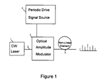
- Fig. 1 shows a block diagram of the invention in its most general form.
- Fig. 2 shows a more specific block diagram of the invention.
- Figure 3a shows the spectrum of the light at the input to the DSF as measured by a Fabry-Perot spectrometer.
- Fig. 3b shows the spectrum at the output of the DSF as measured by an optical spectrum analyzer.
- Fig. 4 shows another embodiment of the invention, in which the amplitude modulator comprises a periodically driven phase modulator and linear dispersive fiber.
- Fig. 5a shows the optical signal spectrum from figure 4.
- Fig. 5b shows the spectrum of the output light of the embodiment of figure 4.
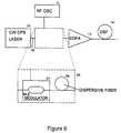
- Fig. 6 shows a second alternative embodiment, in which the periodic amplitude modulation is generated by inserting a linear dispersive element after the Mach-Zehnder modulator to modify the amplitude modulated waveform.
- Fig. 7 shows a block diagram of the invention in use in a four-channel WDM data transmitter.
- Fig. 8 shows a block diagram of the invention used as a tunable light source.
- MMWS multi-wavelength source
- An optical modulator (3) driven by a periodic signal (4) imposes periodic amplitude modulation on light (2) from a single longitudinal mode CW laser (1).
- the light is then coupled to a non-linear medium (5) with an intensity dependent refractive index where it generates higher order spectral sidebands by the process of self-phase modulation.
- the frequency spacing between the spectral components is equal to the repetition rate of the modulation.
- the shape of the spectrum i.e. the relative amplitudes of the spectral components
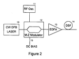
- the basic configuration of a practical MWS is shown in Fig. 2.
- a similar configuration has been used by others to generate optical soliton pulses for use in a soliton transmission system (E. A. Swanson and S. R. Chinn, "40-GHz Pulse Train Generation Using Soliton Compression of a Mach-Zehnder Modulator Output, " IEEE Photon. Technol. Lett., vol. 7, no. 1, pp. 114-116, Jan. 1995).
- the present invention comprises the use of this arrangement as a multi-wavelength source, an effective and novel system for generating a plurality of spaced-apart wavelength coherent light signals from a single laser source. Two alternative methods to attain the periodic amplitude modulated optical signal are described.
- a lithium niobate Mach-Zehnder interferometer modulator (12) was used to generate the periodic amplitude modulation on the CW light from a distributed-feedback laser (DFB) (10).
- DFB distributed-feedback laser
- the electrode on each of the two arms of the modulator (12) were driven with 16 GHz sinusoidal electrical signals of opposite polarity and equal magnitude from an RF Oscillator (11).
- a DC bias voltage (15) was applied to the modulator to bias it at a maximum of its raised cosine switching characteristic and, thereby, generate periodic amplitude modulation at a repetition rate of 32 GHz.
- This amplitude modulated light was amplified to 53 mW using an erbium-doped fiber amplifier (EDFA) (13) and coupled to 22.6 km of dispersion-shifted fiber (DSF) (14).
- EDFA erbium-doped fiber amplifier
- DSF dispersion-shifted fiber
- a directional-coupler type amplitude modulator might be used in place of the Mach-Zender modulator.
- Figure 3a shows the spectrum of the light at the input to the DSF as measured by a Fabry-Perot spectrometer and Fig. 3b was the spectrum at the output of the DSF as measured by an optical spectrum analyzer.
- the optical spectrum coupled to the DSF consisted of only two significant components spaced 64 GHz apart.
- the spectrum contained seven components within 3 dB in amplitude and eleven components within 10 dB. These spectral components were separated by 32 GHz - which is the repetition rate of the amplitude modulation and twice the modulator drive frequency.
- the quality of the wavelength channels produced by the MWS were evaluated by selecting a channel with an optical filter, modulating it at 2.5 Gb/s, and testing for errors. The four wavelength channels tested had less than a 0.4 dB penalty as compared to using the CW light of a DFB laser as the optical source.
- An alternative method of generating the periodic amplitude modulation is to periodically phase modulate the CW light and then convert it to amplitude modulation using a linear dispersive element, as is presented in figure 4.
- the amplitude modulator of figure 2 is replaced with a modulator (45) which comprises a sinusoidally driven phase modulator (47) and linear dispersive fiber (46) as shown in Fig.4.
- CW light from a DFB laser (10) is coupled through an optical fiber (48) to an electro-optic phase modulator (47) that is driven by sinusoidal electrical signals from an RF oscillator (11).
- the periodic phase modulated optical signal is coupled to a linear dispersive optical fiber (46) which converts it to a periodic amplitude modulated optical signal.
- the periodic amplitude modulated optical signal is coupled to an EDFA (13) in which it is amplified.
- the amplified optical signal is then coupled to a DSF (14) which generates additional frequency components in the spectrum of the optical signal by the process of self-phase modulation.
- This configuration allows the production of a spectrum at the input end of the DSF (14) with more spectral components, although the frequency doubling feature of the Mach-Zehnder modulator is sacrificed.
- the optical signal whose spectrum is shown in Fig. 5a, was amplified to 63 mW and coupled to the DSF (14).
- the spectrum of the output light contained 21 spectral components within 10 dB in amplitude and, if the carrier is neglected, had 20 components within 6 dB.
- the spectral components were spaced by 12 GHz which was the drive frequency of the modulator.
- FIG. 6 A second alternative method of generating the periodic amplitude modulation is shown in Fig. 6.
- a linear dispersive element (66) is inserted after the Mach-Zehnder modulator (67) in the modulator (65) to modify the amplitude modulated waveform.
- the M-Z modulator (67) is driven to generate an optical signal with a spectrum consisting predominantly of two components spaced in frequency by 4 ⁇ f where f is the frequency of electrical drive frequency. This is achieved if the peak-to-peak phase modulation induced in each arm of the M-Z modulator (67) is from about 4.2 to 4.8 radians.
- the optical signal is then coupled to a linear dispersive element (66) with first order dispersion equal to ⁇ c/(8 ⁇ 2 f 2 ) or ⁇ c/(24 ⁇ 2 f 2 ) and negligible higher order dispersion.
- c is the speed of light in a vacuum
- ⁇ is the wavelength of the CW light.
- a dual-drive version of that modulator whose electrodes are driven by 50 GHz sinusoidal signals of only 300 mW would be able to produce the first spectrum described above but with a 100 GHz spacing between the components. Driving such a modulator harder would generate a spectrum with more components.
- FIG. 7 shows how the multi-wavelength source (MWS) of the invention (71) is used in a wavelength-division multiplex (WDM) transmitter, here shown with four channels, although it will be understood that any number of channels could be used.
- the MWS (71), as discussed above, is made up of a CW laser (70) feeding an optical modulator (73) such as a Mach-Zender modulator, which is modulated by a periodic source such as RF oscillator (72), which has an RF output frequency ⁇ of, for example, 32 GHz.
- the output of the modulator (73) is fed into a non-linear element (79), such as a length of dispersion-shifted fiber.
- the output (80) of the MWS (71) is made up of a plurality of optical light signals, with wavelengths separated by ⁇ or, in some configurations, a multiple of ⁇ .
- the output (80) of the MWS (71) is preferably fed into wavelength-division demultiplexer (DeMUX)(84), which separates each of the components of the MWS into single-wavelength optical output (74a)-(74d).
- Each output of the DeMUX (74a)-(74d) is fed into an optical modulator (75a)-(75d).
- Each modulator (75a)-(75d) is fed with a separate data signal (78a)-(78d), one data signal per channel in the WDM system .
- the outputs of the modulators (75a)-(75d), each comprising a modulated optical signal representing one channel of data in the WDM system, are combined in a combiner (76) or wavelength multiplexer, and sent out over the optical fiber (77). If desired, however, the various signals could be kept separate and not combined.
- BPF band-pass filters
- the MWS of the invention can also be used to form a tunable light source, as shown in figure 8.
- the elements of the MWS (71) are the same as discussed above.
- the output (80) of the MWS (71), as noted above, comprises a plurality of optical light signals of differing wavelengths, spaced apart by the frequency ⁇ of the RF oscillator (72) (or by a multiple of ⁇ ).
- the output (80) is fed into a tunable filter (81), then one of the plurality of light signals may be selected out, and output (82) into other equipment which might need a light source of that wavelength (color).
Landscapes
- Physics & Mathematics (AREA)
- Nonlinear Science (AREA)
- Engineering & Computer Science (AREA)
- Optics & Photonics (AREA)
- Electromagnetism (AREA)
- Computer Networks & Wireless Communication (AREA)
- Signal Processing (AREA)
- General Physics & Mathematics (AREA)
- Chemical & Material Sciences (AREA)
- Ceramic Engineering (AREA)
- Crystallography & Structural Chemistry (AREA)
- Optical Modulation, Optical Deflection, Nonlinear Optics, Optical Demodulation, Optical Logic Elements (AREA)
- Optical Communication System (AREA)
- Lasers (AREA)
Applications Claiming Priority (2)
| Application Number | Priority Date | Filing Date | Title |
|---|---|---|---|
| US08/799,330 US5963567A (en) | 1997-02-13 | 1997-02-13 | Multi-wavelength laser source |
| US799330 | 1997-02-13 |
Publications (3)
| Publication Number | Publication Date |
|---|---|
| EP0859266A2 true EP0859266A2 (fr) | 1998-08-19 |
| EP0859266A3 EP0859266A3 (fr) | 2001-02-07 |
| EP0859266B1 EP0859266B1 (fr) | 2009-09-16 |
Family
ID=25175608
Family Applications (1)
| Application Number | Title | Priority Date | Filing Date |
|---|---|---|---|
| EP98300749A Expired - Lifetime EP0859266B1 (fr) | 1997-02-13 | 1998-02-03 | Source laser à longueurs d'onde multiples |
Country Status (6)
| Country | Link |
|---|---|
| US (1) | US5963567A (fr) |
| EP (1) | EP0859266B1 (fr) |
| JP (1) | JPH10228038A (fr) |
| KR (1) | KR19980071330A (fr) |
| CA (1) | CA2227207C (fr) |
| DE (1) | DE69841147D1 (fr) |
Cited By (10)
| Publication number | Priority date | Publication date | Assignee | Title |
|---|---|---|---|---|
| EP1245997A1 (fr) * | 2001-03-27 | 2002-10-02 | The Furukawa Electric Co., Ltd. | Source lumineuse multifréquence par mélange à quatre ondes |
| EP1369742A1 (fr) * | 2002-06-03 | 2003-12-10 | Nippon Telegraph and Telephone Corporation | Dispositif et procédé pour générer un signal radiofréquence standard |
| WO2002074037A3 (fr) * | 2001-03-16 | 2003-12-11 | Roke Manor Research | Dispositif et procede de compression de donnees |
| EP1288705A3 (fr) * | 2001-08-28 | 2005-03-02 | Nippon Telegraph and Telephone Corporation | Source de lumière pulsée accordable en longueur d'onde |
| KR100516664B1 (ko) * | 2002-12-14 | 2005-09-22 | 삼성전자주식회사 | 수동형 광가입자망 |
| US7054057B2 (en) | 2001-03-27 | 2006-05-30 | The Furukawa Electric Co., Ltd. | Multi-frequency light source |
| WO2007123614A1 (fr) * | 2006-03-31 | 2007-11-01 | Lucent Technologies Inc. | Generateur d'ondes terahertziennes |
| CN100355159C (zh) * | 2001-03-28 | 2007-12-12 | 三星电子株式会社 | 可调光振荡器 |
| WO2008129492A3 (fr) * | 2007-04-19 | 2009-02-12 | Gabriele Ferrari | Procédé et dispositif permettant la détermination d'une relation de phase entre des champs optiques et des champs radiofréquence ou microonde |
| US12547047B1 (en) * | 2020-10-28 | 2026-02-10 | Cable Television Laboratories, Inc. | Frequency-comb source and generation and method |
Families Citing this family (66)
| Publication number | Priority date | Publication date | Assignee | Title |
|---|---|---|---|---|
| JPH10303822A (ja) * | 1997-04-25 | 1998-11-13 | Furukawa Electric Co Ltd:The | 光送信装置 |
| DE19737482A1 (de) * | 1997-08-28 | 1999-03-04 | Alsthom Cge Alcatel | Verfahren zur optischen Übertragung über ein Lichtwellenleiternetz, sowie optisches Übertragungsnetz |
| US6118565A (en) * | 1997-09-30 | 2000-09-12 | Lucent Technologies Inc. | Coherent optical communication system |
| US6201638B1 (en) * | 1998-01-23 | 2001-03-13 | University Technology Corporation | Comb generating optical cavity that includes an optical amplifier and an optical modulator |
| US6549311B1 (en) * | 1999-07-14 | 2003-04-15 | Lucent Technologies Inc. | Wave division multiplexing channel telemetry by phase modulation |
| US6970654B1 (en) * | 1999-08-05 | 2005-11-29 | Sarnoff Corporation | Optical signal generator |
| US6424669B1 (en) * | 1999-10-29 | 2002-07-23 | E20 Communications, Inc. | Integrated optically pumped vertical cavity surface emitting laser |
| US6804471B1 (en) * | 2000-01-05 | 2004-10-12 | Hrl Laboratories Llc | Apparatus and method of pulsed frequency modulation for analog optical communication |
| US6901224B1 (en) | 2000-02-18 | 2005-05-31 | Northrop Grumman Corporation | Hybrid coherent-optical, RF signal channelizer |
| FR2806559B1 (fr) * | 2000-03-20 | 2002-05-31 | Cit Alcatel | Regenerateur optique synchrone par modulation d'intensite et modulation de phase par effet kerr croise |
| US6560255B1 (en) | 2000-03-24 | 2003-05-06 | Agere Systems Inc. | Method and apparatus for characterizing laser modules |
| US20070047885A1 (en) * | 2000-11-21 | 2007-03-01 | Yaron Mayer | System and method for transferring much more information in optic fiber cables by significantly increasing the number of fibers per cable |
| US20020085257A1 (en) * | 2001-01-04 | 2002-07-04 | Hirt Fred S. | Optical modulator linearization by direct radio frequency (RF) feedback |
| US6847477B2 (en) | 2001-02-28 | 2005-01-25 | Kilolamdia Ip Limited | Optical system for converting light beam into plurality of beams having different wavelengths |
| US6619864B2 (en) | 2001-03-15 | 2003-09-16 | Optinel Systems, Inc. | Optical channel monitor with continuous gas cell calibration |
| US6407846B1 (en) | 2001-03-16 | 2002-06-18 | All Optical Networks, Inc. | Photonic wavelength shifting method |
| US20020131125A1 (en) * | 2001-03-16 | 2002-09-19 | Myers Michael H. | Replicated-spectrum photonic transceiving |
| US6959153B2 (en) * | 2001-05-24 | 2005-10-25 | Broadband Royalty Corporation | Dynamically reconfigurable add/drop multiplexer with low coherent cross-talk for optical communication networks |
| US6993257B2 (en) * | 2001-08-15 | 2006-01-31 | Broadband Royalty Corporation | Optical channel monitor utilizing multiple Fabry-Perot filter pass-bands |
| US6826207B2 (en) * | 2001-12-17 | 2004-11-30 | Peleton Photonic Systems Inc. | Multi-wavelength laser source based on two optical laser beat signal and method |
| US7295584B2 (en) * | 2001-12-17 | 2007-11-13 | Peleton Photonic Systems | System and method for generating multi-wavelength laser source using highly nonlinear fiber |
| US6738536B2 (en) * | 2001-12-20 | 2004-05-18 | Optinel Systems, Inc. | Wavelength tunable filter device for fiber optic systems |
| JP3881270B2 (ja) * | 2002-03-26 | 2007-02-14 | 富士通株式会社 | 光変調器の駆動制御装置および駆動制御方法 |
| US6996345B1 (en) * | 2002-05-10 | 2006-02-07 | The United States Of America As Represented By The Secretary Of The Air Force | Linearization of intensity modulators using quadratic electro-optic effect |
| US7076120B2 (en) * | 2002-07-08 | 2006-07-11 | Lucent Technologies Inc. | Optical pulse generator for return-to-zero signaling |
| US20040057735A1 (en) * | 2002-09-23 | 2004-03-25 | Katsumi Uesaka | Optical transmitter using highly nonlinear fiber and method |
| KR100438426B1 (ko) * | 2002-10-18 | 2004-07-03 | 삼성전자주식회사 | 무편광 다파장 광원 |
| US6907052B2 (en) * | 2003-02-19 | 2005-06-14 | The Aerospace Corporation | Tunable optical local oscillator |
| US7277617B2 (en) * | 2003-05-07 | 2007-10-02 | Intel Corporation | Optical pulse compressor based on integrated planar lightwave circuit: method, device, and systems |
| US20050053022A1 (en) * | 2003-08-28 | 2005-03-10 | The Boeing Company | Encoding and merging multiple data streams of fibre channel network |
| US7573902B2 (en) | 2003-08-28 | 2009-08-11 | The Boeing Company | Fibre channel interface unit |
| US7729374B2 (en) * | 2003-08-28 | 2010-06-01 | The Boeing Company | Fibre channel interface apparatus and methods |
| US7848655B2 (en) * | 2003-08-28 | 2010-12-07 | Telcordia Technologies, Inc. | Mode-locked optical amplifier as a source for a wdm-WDM hierarchy architecture |
| JP2005192046A (ja) * | 2003-12-26 | 2005-07-14 | Fujitsu Ltd | パルス発生装置および方法 |
| US7385706B2 (en) * | 2004-09-24 | 2008-06-10 | Lucent Technologies Inc. | Method and apparatus for determining the nonlinear properties of devices and fibers |
| US20060090341A1 (en) * | 2004-10-30 | 2006-05-04 | Schroepfer David J | Method of manufacturing solid ring wheel rims |
| KR100715865B1 (ko) | 2005-03-03 | 2007-05-11 | 광주과학기술원 | 반도체 광증폭기 마하젠더 간섭계를 이용한 전광 주파수 상향 변환 방법 |
| DE102005012699A1 (de) * | 2005-03-18 | 2006-09-28 | Siemens Ag | Verfahren zur medizinischen Bildgebung sowie medizinisches bildgebendes System |
| FR2884086A1 (fr) * | 2005-04-05 | 2006-10-06 | France Telecom | Transmission optique entre une premiere unite et une pluralite de secondes unites connectees entre elles au moyen d'un reseau d'acces optique passif |
| JP4786383B2 (ja) * | 2006-03-27 | 2011-10-05 | 富士通株式会社 | 光送信装置 |
| JP4515436B2 (ja) * | 2006-10-30 | 2010-07-28 | 富士通株式会社 | 装置 |
| WO2008151370A1 (fr) * | 2007-06-14 | 2008-12-18 | The University Of Sydney | Traitement optique haute fréquence |
| US20090067843A1 (en) * | 2007-07-17 | 2009-03-12 | Way Winston I | Optical Wavelength-Division-Multiplexed (WDM) Comb Generator Using a Single Laser |
| US8238759B2 (en) * | 2008-02-14 | 2012-08-07 | Infinera Corporation | High capacity transmitter implemented on a photonic integrated circuit |
| US8260145B2 (en) | 2008-03-12 | 2012-09-04 | Deepnarayan Gupta | Digital radio frequency tranceiver system and method |
| US8750709B1 (en) | 2008-07-18 | 2014-06-10 | Hrl Laboratories, Llc | RF receiver front-end assembly |
| US8180183B1 (en) | 2008-07-18 | 2012-05-15 | Hrl Laboratories, Llc | Parallel modulator photonic link |
| US8059969B1 (en) * | 2008-06-18 | 2011-11-15 | Hrl Laboratories, Llc | Enhanced linearity RF photonic link |
| US8995838B1 (en) | 2008-06-18 | 2015-03-31 | Hrl Laboratories, Llc | Waveguide assembly for a microwave receiver with electro-optic modulator |
| US8285147B2 (en) * | 2008-07-31 | 2012-10-09 | Lg-Ericsson Co., Ltd. | Bulk modulation of multiple wavelengths for generation of CATV optical comb |
| US8693875B2 (en) * | 2008-11-20 | 2014-04-08 | Applied Communications Sciences | Method and apparatus for optimized analog RF optical links |
| KR101190862B1 (ko) * | 2008-12-18 | 2012-10-15 | 한국전자통신연구원 | 단일 종모드 발진 광원 기반의 씨앗광 모듈 |
| US9485050B2 (en) | 2009-12-08 | 2016-11-01 | Treq Labs, Inc. | Subchannel photonic routing, switching and protection with simplified upgrades of WDM optical networks |
| DE102010022585B4 (de) * | 2010-06-03 | 2012-03-08 | Bundesrepublik Deutschland, vertreten durch das Bundesministerium für Wirtschaft und Technologie, dieses vertreten durch den Präsidenten der Physikalisch-Technischen Bundesanstalt | Verfahren zum Erzeugen von phasenkohärenten Lichtfeldern mit vorgebbarem Wert ihrer Frequenz und optischer Frequenz-Synthesizer |
| US9335568B1 (en) | 2011-06-02 | 2016-05-10 | Hrl Laboratories, Llc | Electro-optic grating modulator |
| US20120321320A1 (en) * | 2011-06-17 | 2012-12-20 | Nec Laboratories America, Inc. | Generation and Direct Detection of Orthogonal Band Multiplexing OFDM Signal with Optical Carriers |
| US9366937B2 (en) * | 2012-01-13 | 2016-06-14 | Sumitomo Osaka Cement Co., Ltd. | Optical pulse-generator |
| US8611759B1 (en) * | 2012-02-07 | 2013-12-17 | The United States Of America As Represented By The Secretary Of The Navy | Optical domain wideband RF spectrum analyzer/channelizer based on third-order nonlinear mixing |
| EP2915002A1 (fr) * | 2012-10-31 | 2015-09-09 | Commissariat à l'Énergie Atomique et aux Énergies Alternatives | Dispositif de génération d'une modulation d'un signal optique comportant des modulateurs à électro-absorption |
| KR20140147321A (ko) * | 2013-06-19 | 2014-12-30 | 한국전자통신연구원 | 파장 훑음 광원 장치 및 그것의 작동 방법 |
| CN104333419A (zh) * | 2014-09-25 | 2015-02-04 | 华中科技大学 | 一种可调谐多波长光源及其调制方法 |
| JP6533171B2 (ja) * | 2016-03-03 | 2019-06-19 | 日本電信電話株式会社 | 光コム発生装置 |
| US10411810B2 (en) | 2016-07-04 | 2019-09-10 | The Regents Of The University Of California | Receiver with mutually coherent optical frequency combs |
| US10523329B2 (en) | 2016-11-07 | 2019-12-31 | The Regents Of The University Of California | Comb-assisted cyclostationary analysis |
| WO2019010439A1 (fr) | 2017-07-07 | 2019-01-10 | The Regents Of The University Of California | Système et procédé d'amélioration de la sensibilité d'un récepteur |
| WO2025227087A1 (fr) * | 2024-04-26 | 2025-10-30 | Ntt Research, Inc. | Génération d'un peigne de fréquence optique à l'aide d'une modulation électro-optique dans un oscillateur paramétrique optique |
Family Cites Families (4)
| Publication number | Priority date | Publication date | Assignee | Title |
|---|---|---|---|---|
| US5295209A (en) * | 1991-03-12 | 1994-03-15 | General Instrument Corporation | Spontaneous emission source having high spectral density at a desired wavelength |
| US5596667A (en) * | 1992-10-20 | 1997-01-21 | Fujitsu Limited | Application of phase conjugate optics to optical systems |
| JP3199106B2 (ja) * | 1995-04-17 | 2001-08-13 | 日本電信電話株式会社 | 多波長光源およびそれを用いた光波長多重信号発生回路 |
| US5778015A (en) * | 1996-05-16 | 1998-07-07 | British Telecommunications Public Limited Company | Optical Pulse source |
-
1997
- 1997-02-13 US US08/799,330 patent/US5963567A/en not_active Expired - Lifetime
-
1998
- 1998-01-19 CA CA002227207A patent/CA2227207C/fr not_active Expired - Fee Related
- 1998-02-03 EP EP98300749A patent/EP0859266B1/fr not_active Expired - Lifetime
- 1998-02-03 DE DE69841147T patent/DE69841147D1/de not_active Expired - Lifetime
- 1998-02-06 JP JP10026176A patent/JPH10228038A/ja active Pending
- 1998-02-13 KR KR1019980004309A patent/KR19980071330A/ko not_active Ceased
Cited By (12)
| Publication number | Priority date | Publication date | Assignee | Title |
|---|---|---|---|---|
| WO2002074037A3 (fr) * | 2001-03-16 | 2003-12-11 | Roke Manor Research | Dispositif et procede de compression de donnees |
| EP1245997A1 (fr) * | 2001-03-27 | 2002-10-02 | The Furukawa Electric Co., Ltd. | Source lumineuse multifréquence par mélange à quatre ondes |
| US7054057B2 (en) | 2001-03-27 | 2006-05-30 | The Furukawa Electric Co., Ltd. | Multi-frequency light source |
| US7408701B2 (en) | 2001-03-27 | 2008-08-05 | The Furukawa Electric Co., Ltd. | Multi-frequency light source |
| CN100355159C (zh) * | 2001-03-28 | 2007-12-12 | 三星电子株式会社 | 可调光振荡器 |
| EP1288705A3 (fr) * | 2001-08-28 | 2005-03-02 | Nippon Telegraph and Telephone Corporation | Source de lumière pulsée accordable en longueur d'onde |
| EP1369742A1 (fr) * | 2002-06-03 | 2003-12-10 | Nippon Telegraph and Telephone Corporation | Dispositif et procédé pour générer un signal radiofréquence standard |
| US7373086B2 (en) | 2002-06-03 | 2008-05-13 | Nippon Telegraph And Telephone Corporation | Standard radio frequency signal generating method and standard radio frequency signal generating device |
| KR100516664B1 (ko) * | 2002-12-14 | 2005-09-22 | 삼성전자주식회사 | 수동형 광가입자망 |
| WO2007123614A1 (fr) * | 2006-03-31 | 2007-11-01 | Lucent Technologies Inc. | Generateur d'ondes terahertziennes |
| WO2008129492A3 (fr) * | 2007-04-19 | 2009-02-12 | Gabriele Ferrari | Procédé et dispositif permettant la détermination d'une relation de phase entre des champs optiques et des champs radiofréquence ou microonde |
| US12547047B1 (en) * | 2020-10-28 | 2026-02-10 | Cable Television Laboratories, Inc. | Frequency-comb source and generation and method |
Also Published As
| Publication number | Publication date |
|---|---|
| CA2227207A1 (fr) | 1998-08-13 |
| EP0859266B1 (fr) | 2009-09-16 |
| DE69841147D1 (de) | 2009-10-29 |
| CA2227207C (fr) | 2001-09-04 |
| KR19980071330A (ko) | 1998-10-26 |
| JPH10228038A (ja) | 1998-08-25 |
| EP0859266A3 (fr) | 2001-02-07 |
| US5963567A (en) | 1999-10-05 |
Similar Documents
| Publication | Publication Date | Title |
|---|---|---|
| US5963567A (en) | Multi-wavelength laser source | |
| Veselka et al. | A multiwavelength source having precise channel spacing for WDM systems | |
| US5625722A (en) | Method and apparatus for generating data encoded pulses in return-to-zero format | |
| US5959764A (en) | Wavelength converter, optically operational device and optical pulse phase detecting circuit | |
| US5063559A (en) | Optimized wavelength-division-multiplexed lightwave communication system | |
| EP1303932B1 (fr) | Generateur de trains d'impulsions optiques | |
| CA2058638A1 (fr) | Modulateur optique a bande laterale unique pour systemes a ondes lumineuses | |
| JP2004037985A (ja) | 光andゲート及び波形成形装置 | |
| US6438148B1 (en) | Method and device for encoding data into high speed optical train | |
| JP4444689B2 (ja) | 光通信用光装置 | |
| US20070030556A1 (en) | Optical frequency converter | |
| CN110989210A (zh) | 基于eam和脉冲信号的可调谐光学频率梳产生装置及方法 | |
| US20030174386A1 (en) | Optical communication system | |
| Shimotsu et al. | Wideband frequency conversion with LiNbO3 optical single-sideband modulator | |
| JP2004294543A (ja) | 周期的多波長光発生装置 | |
| US5493438A (en) | Amplitude optical modulator using a two-electrode DFB laser structure | |
| CN119890915B (zh) | 超短光脉冲源芯片和超短光脉冲源设备 | |
| Shen et al. | Low-cost, continuously tunable, millimeter-wave photonic LO generation using optical phase modulation and DWDM filters | |
| Lima et al. | Tunable Optical Frequency Comb Generation Applied to DWDM and 5G Networks | |
| Tsujishita et al. | Generation of Modulated THz Waves Using a Two-Wavelength Tunable Silicon Photonics Heterogeneous Laser Diode | |
| Wang et al. | Multiband Linearly Frequency-Modulated Signal Generation Based on an Optical Integrated Cascade Microring Filter | |
| Asobe et al. | High-speed wavelength switching of 40-Gb/s-based WDM signals using a multiple-QPM LiNbO/sub 3/waveguide tailored for the ITU-T grid | |
| Rusalov | EE 558 WDM components | |
| Raybon et al. | An integrated WDM soliton source using sinusoidally driven electroabsorption modulators in a 16× 1 laser/modulator array | |
| JPH06118460A (ja) | 光位相変調回路 |
Legal Events
| Date | Code | Title | Description |
|---|---|---|---|
| PUAI | Public reference made under article 153(3) epc to a published international application that has entered the european phase |
Free format text: ORIGINAL CODE: 0009012 |
|
| AK | Designated contracting states |
Kind code of ref document: A2 Designated state(s): DE FR GB |
|
| AX | Request for extension of the european patent |
Free format text: AL;LT;LV;MK;RO;SI |
|
| PUAL | Search report despatched |
Free format text: ORIGINAL CODE: 0009013 |
|
| AK | Designated contracting states |
Kind code of ref document: A3 Designated state(s): AT BE CH DE DK ES FI FR GB GR IE IT LI LU MC NL PT SE |
|
| AX | Request for extension of the european patent |
Free format text: AL;LT;LV;MK;RO;SI |
|
| 17P | Request for examination filed |
Effective date: 20010807 |
|
| AKX | Designation fees paid |
Free format text: DE FR GB |
|
| 17Q | First examination report despatched |
Effective date: 20070115 |
|
| GRAP | Despatch of communication of intention to grant a patent |
Free format text: ORIGINAL CODE: EPIDOSNIGR1 |
|
| GRAS | Grant fee paid |
Free format text: ORIGINAL CODE: EPIDOSNIGR3 |
|
| GRAA | (expected) grant |
Free format text: ORIGINAL CODE: 0009210 |
|
| RAP3 | Party data changed (applicant data changed or rights of an application transferred) |
Owner name: LUCENT TECHNOLOGIES INC. |
|
| AK | Designated contracting states |
Kind code of ref document: B1 Designated state(s): DE FR GB |
|
| REG | Reference to a national code |
Ref country code: GB Ref legal event code: FG4D |
|
| REF | Corresponds to: |
Ref document number: 69841147 Country of ref document: DE Date of ref document: 20091029 Kind code of ref document: P |
|
| PLBE | No opposition filed within time limit |
Free format text: ORIGINAL CODE: 0009261 |
|
| STAA | Information on the status of an ep patent application or granted ep patent |
Free format text: STATUS: NO OPPOSITION FILED WITHIN TIME LIMIT |
|
| 26N | No opposition filed |
Effective date: 20100617 |
|
| PGFP | Annual fee paid to national office [announced via postgrant information from national office to epo] |
Ref country code: FR Payment date: 20140211 Year of fee payment: 17 |
|
| REG | Reference to a national code |
Ref country code: DE Ref legal event code: R082 Ref document number: 69841147 Country of ref document: DE Representative=s name: DILG HAEUSLER SCHINDELMANN PATENTANWALTSGESELL, DE |
|
| REG | Reference to a national code |
Ref country code: FR Ref legal event code: ST Effective date: 20151030 |
|
| PG25 | Lapsed in a contracting state [announced via postgrant information from national office to epo] |
Ref country code: FR Free format text: LAPSE BECAUSE OF NON-PAYMENT OF DUE FEES Effective date: 20150302 |
|
| PGFP | Annual fee paid to national office [announced via postgrant information from national office to epo] |
Ref country code: DE Payment date: 20160121 Year of fee payment: 19 |
|
| PGFP | Annual fee paid to national office [announced via postgrant information from national office to epo] |
Ref country code: GB Payment date: 20160127 Year of fee payment: 19 |
|
| REG | Reference to a national code |
Ref country code: DE Ref legal event code: R119 Ref document number: 69841147 Country of ref document: DE |
|
| GBPC | Gb: european patent ceased through non-payment of renewal fee |
Effective date: 20170203 |
|
| PG25 | Lapsed in a contracting state [announced via postgrant information from national office to epo] |
Ref country code: DE Free format text: LAPSE BECAUSE OF NON-PAYMENT OF DUE FEES Effective date: 20170901 |
|
| PG25 | Lapsed in a contracting state [announced via postgrant information from national office to epo] |
Ref country code: GB Free format text: LAPSE BECAUSE OF NON-PAYMENT OF DUE FEES Effective date: 20170203 |