EP0859391A2 - Commutateur dépendant de la température avec étrier de retenue - Google Patents
Commutateur dépendant de la température avec étrier de retenue Download PDFInfo
- Publication number
- EP0859391A2 EP0859391A2 EP97118321A EP97118321A EP0859391A2 EP 0859391 A2 EP0859391 A2 EP 0859391A2 EP 97118321 A EP97118321 A EP 97118321A EP 97118321 A EP97118321 A EP 97118321A EP 0859391 A2 EP0859391 A2 EP 0859391A2
- Authority
- EP
- European Patent Office
- Prior art keywords
- housing
- plastic part
- bracket
- connection
- Prior art date
- Legal status (The legal status is an assumption and is not a legal conclusion. Google has not performed a legal analysis and makes no representation as to the accuracy of the status listed.)
- Granted
Links
- 230000001419 dependent effect Effects 0.000 title claims abstract description 12
- 239000004033 plastic Substances 0.000 claims abstract description 47
- 239000002184 metal Substances 0.000 claims abstract description 30
- 238000004519 manufacturing process Methods 0.000 claims description 9
- 238000005538 encapsulation Methods 0.000 claims description 2
- 230000008901 benefit Effects 0.000 description 9
- 230000008878 coupling Effects 0.000 description 8
- 238000010168 coupling process Methods 0.000 description 8
- 238000005859 coupling reaction Methods 0.000 description 8
- 238000010438 heat treatment Methods 0.000 description 5
- 238000009413 insulation Methods 0.000 description 3
- 230000033228 biological regulation Effects 0.000 description 2
- 239000003292 glue Substances 0.000 description 2
- 230000017525 heat dissipation Effects 0.000 description 2
- 230000007246 mechanism Effects 0.000 description 2
- 239000002991 molded plastic Substances 0.000 description 2
- 238000000465 moulding Methods 0.000 description 2
- XLYOFNOQVPJJNP-UHFFFAOYSA-N water Substances O XLYOFNOQVPJJNP-UHFFFAOYSA-N 0.000 description 2
- 238000003466 welding Methods 0.000 description 2
- 238000004804 winding Methods 0.000 description 2
- 230000009471 action Effects 0.000 description 1
- 238000010411 cooking Methods 0.000 description 1
- 238000005520 cutting process Methods 0.000 description 1
- 230000001934 delay Effects 0.000 description 1
- 230000005284 excitation Effects 0.000 description 1
- 238000009434 installation Methods 0.000 description 1
- 238000012544 monitoring process Methods 0.000 description 1
- 229920000642 polymer Polymers 0.000 description 1
- 238000003825 pressing Methods 0.000 description 1
- 230000001681 protective effect Effects 0.000 description 1
- 230000004044 response Effects 0.000 description 1
- 238000007789 sealing Methods 0.000 description 1
- 230000035939 shock Effects 0.000 description 1
- 238000005507 spraying Methods 0.000 description 1
Images


Classifications
-
- H—ELECTRICITY
- H01—ELECTRIC ELEMENTS
- H01H—ELECTRIC SWITCHES; RELAYS; SELECTORS; EMERGENCY PROTECTIVE DEVICES
- H01H37/00—Thermally-actuated switches
- H01H37/02—Details
- H01H37/32—Thermally-sensitive members
- H01H37/52—Thermally-sensitive members actuated due to deflection of bimetallic element
- H01H37/54—Thermally-sensitive members actuated due to deflection of bimetallic element wherein the bimetallic element is inherently snap acting
- H01H37/5427—Thermally-sensitive members actuated due to deflection of bimetallic element wherein the bimetallic element is inherently snap acting encapsulated in sealed miniaturised housing
-
- H—ELECTRICITY
- H01—ELECTRIC ELEMENTS
- H01H—ELECTRIC SWITCHES; RELAYS; SELECTORS; EMERGENCY PROTECTIVE DEVICES
- H01H9/00—Details of switching devices, not covered by groups H01H1/00 - H01H7/00
- H01H9/12—Means for earthing parts of switch not normally conductively connected to the contacts
Definitions
- the present invention relates to a device for protection of an electrical device from overtemperature, with a temperature-dependent switch with a housing at the bottom a first connection contact is provided, one on the housing provided second connection contact and a holder that the housing carries and one with the second connection contact connected external connection.
- a device of the aforementioned type is known from the DE 38 17 080 C2 known.
- the known device comprises a holder made of plastic, in which a temperature-dependent switch with two parts Metal housing is arranged.
- the connection contacts of the temperature-dependent Switch are once through the metal cover and formed on the other by the metal lower part, wherein in Inside the switch, a bimetal switch mechanism known per se is arranged.
- the known device is based on connecting lugs of an electric motor attached and has a connection lug itself, which is accessible from the outside.
- connection lug of the holder is with a contact plate connected, when the device is attached to the electric motor rests directly on the field winding.
- the metal housing On the contact plate the metal housing with its inside the holder Ground on so that a thermal contact to the electric motor and an electrical contact to the terminal lug of the holder consists.
- connection spring presses on the metal cover Connection flag of the electric motor is connected, however, after the attachment of the device is no longer accessible from the outside is.
- the second connecting lug of the electric motor and the Terminal lug of the holder serve as external connections of the the known device provided electric motor.
- the arrangement described is temperature-dependent Switches in series with the electric motor between the two External connections arranged.
- the temperature is now increasing the excitation winding beyond a predetermined value, so the bimetal switchgear opens the electrical contact between the metal cover and the metal base, so that one to the External connections applied electrical voltage to the electric motor can no longer supply. This prevents that the electric motor is in operation over a predetermined Temperature warms up, so it becomes overtemperature protected.
- the known device is not for many applications suitable because the holder used there is much too is bulky to work on small electrical household appliances, such as. a coffee machine, an electric kettle or electric hotplates.
- Another The disadvantage of the known device is that it do not follow rapid temperature changes without delay can heat because of the metal cover and the metal base is led to the connecting lugs.
- this object is achieved solved that the holder against the bottom of the housing electrically isolated and designed to be installed in the device Condition the bottom of the case to one provided on the device To press the contact surface.
- the inventors of the present application have recognized that that it is with a temperature-dependent switch, as in the known device is used, the electrical Connecting and connecting the thermal coupling, which is no problem, particularly with flat thick-film heating systems is possible. Benefit from the fact that good electrical contact always good thermal contact is so that by pressing the bottom of the housing good thermal coupling of the switch to the one to be protected Device results.
- Another advantage is the great security of the new one Device, namely the holder can be screwed or be welded on while the bottom of the case is using thermal paste or the like can be glued to the contact surface can. But there are two mechanical breakpoints that are geometrically spaced from each other, so that a more secure Guaranteed hold of the new device on the device to be protected is.
- the holder has a includes to be attached to the device bracket that a Plastic part on which the housing and the external connection are arranged.
- the housing Plastic part is thermally insulated so that only the minor Mass of the housing itself and, if applicable, the one connected to it follow the external connection of the temperature of the device to be protected have to.
- only a very small amount of heat is required for this, the very good because of the good thermal coupling can be transferred quickly, so that the new device overall very quickly to the temperature increases of the protective device can react.
- the holding bracket is the plastic part comprises supporting carrier plate on which a, preferably Two narrow arms are provided, over which the holder attached to the device.
- the advantage here is that the bracket is double, so to speak supplies mechanical hold, so that now together with the already mentioned glue joint a total of three breakpoints for attachment of the new device on the device to be protected are.
- the inventors have found that through this triple Safety also includes mechanical shocks or thermal expansion e.g. with hotplates to be protected do not lead to the fact that the new device thermally or electrically from the device solves.
- the plastic part has a pocket in which the housing with the bottom facing outward is plugged in, and the external connection is a connection lug that is extends through the plastic part to the housing.
- the housing only has to be clamped in the pocket so that it e.g. after pre-assembly of the holder only in the pocket must be pressed in. Furthermore, since the housing is now completely - down to the bottom - is surrounded by the plastic part good thermal insulation so that the floor heat supplied by the device to be protected completely is used to heat the temperature-dependent switch. However, this means that the new device will withstand the temperature changes follows the housing very quickly and when exceeded the specified temperature switches immediately.
- the connecting lug is on is attached to the housing and through one in the plastic part provided slot extends outwards.
- the terminal lug on the Plastic part is attached and - preferably resiliently the housing inserted into the bag.
- the holding bracket is made of metal is made and preferably has an earth connection.
- the device to be protected is advantageous, the metal bracket can now be welded on while holding a bracket screwed or glued plastic, what takes significantly more time. In addition, guaranteed a metal bracket a better mechanical Hold as a plastic bracket.
- the bracket then usually has an earth connection to meet the relevant safety regulations will.
- the plastic part is on the bracket is molded.
- the advantage here is that with a single operation, namely the molding of the plastic part, two more at the same time Manufacturing steps are done with, namely fastening of the plastic part on the bracket and fastening the connecting lug on the plastic part.
- Fig. 1 denotes a new device, the Arrangement on an electrical device 11 to be protected schematically is indicated, the device 10 itself in one first embodiment in a sectional side view you can see.
- the device 10 comprises a bracket 14 which is attached to its each end has a narrow boom 15, the Feet 16 at isolated holding points 17 of the device 11 e.g. by Welding are attached.
- a wider one extends between the narrow arms 15 Carrier plate 18, which carries a molded plastic part 19.
- the switch 22 has a housing 23 preferably made of metal and lies with its cover 24 in contact with an inner end 25 of a connecting lug 26, which extends zigzag through the plastic part 19 and is held firmly by it.
- the terminal lug 26 forms an outer terminal 27 of both the device 10 and the Device 11.
- the bracket 14 itself is made of metal, which is why Ground connection 31 in the form of a bent tab 32 is provided to ground the bracket 14 and thus the Safety regulations especially for electrical household appliances to comply.
- At 34 is yet another external connection of the electrical device 11 shown.
- the electrical device Hot plate with thick film heating is what is called a heating resistor 35 should be hinted at.
- the tab 32 is punched out 37 of the carrier plate 18 lies, that is, in one piece with the carrier plate is made.
- Another punched-out 38, the cutting limit is dashed at 39 is indicated, is in the area of the connecting lug 26 and to recognize the plastic part 19.
- the bracket 14 are the outer contours as well the punched-out 37, 38 cut out, whereupon the Cantilevers 15 are bent with the feet 16 accordingly, as can be seen in Fig. 1.
- connection flag 26 as angled as shown in FIG. 1 in a side view is recognizable.
- plastic part 19 is molded on, whereby the terminal lug 26 is an integral part of the plastic part 14 becomes and with its inner free end 25 in the pocket 21 comes to rest.
- FIG. 3 is a representation similar to FIG. 1 Another embodiment of a new device 10 'shown. 3 is initially clearer to recognize that the switch 22 is a two-part housing 23 Metal, with a first terminal 51 on the Bottom 28 is formed while a second connection contact 52 is formed on a metal cover 54 which in itself in a known manner with respect to a metal lower part 55 electrically is isolated. For the electrical connection between the Metal cover 54 and the metal lower part 55 ensures in a known manner With a schematically indicated bimetallic switching mechanism 56 Spring washer 57 and bimetallic washer 58.
- the spring washer 57 provides electrical Connection between metal cover 54 and metal lower part 55, so that between terminal lug 26 and bottom 28 an electrical Connection exists.
- the temperature of the item to be protected rises Device, so the thermal coupling to the ground 28 also increases the temperature of the switch 22. Reaches that If the temperature reaches a specified value, the bimetallic disc jumps 58 in their other configuration and presses the spring washer 57 away from the metal cover 54 so that the electrical connection between terminal lug 26 and base 28 is interrupted.
- the connecting lug 26 is now not overmolded with the plastic part 19, but sits in a slot 59, which starts from the pocket 21 extends outside.
- the device 10 is assembled in such a way that initially the bracket 14 punched with the support plate 18 and arms 15 and preformed, whereupon the plastic part 19 is injected.
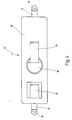
- FIG. 4 is a top view of the new device 10 'shown in FIG. 3.
Landscapes
- Physics & Mathematics (AREA)
- Thermal Sciences (AREA)
- Thermally Actuated Switches (AREA)
- Switch Cases, Indication, And Locking (AREA)
Applications Claiming Priority (2)
| Application Number | Priority Date | Filing Date | Title |
|---|---|---|---|
| DE19705410 | 1997-02-13 | ||
| DE19705410A DE19705410C2 (de) | 1997-02-13 | 1997-02-13 | Temperaturabhängiger Schalter mit Haltebügel |
Publications (3)
| Publication Number | Publication Date |
|---|---|
| EP0859391A2 true EP0859391A2 (fr) | 1998-08-19 |
| EP0859391A3 EP0859391A3 (fr) | 1999-04-21 |
| EP0859391B1 EP0859391B1 (fr) | 2007-02-21 |
Family
ID=7820065
Family Applications (1)
| Application Number | Title | Priority Date | Filing Date |
|---|---|---|---|
| EP97118321A Expired - Lifetime EP0859391B1 (fr) | 1997-02-13 | 1997-10-22 | Commutateur dépendant de la température avec étrier de retenue |
Country Status (4)
| Country | Link |
|---|---|
| US (1) | US5864279A (fr) |
| EP (1) | EP0859391B1 (fr) |
| AT (1) | ATE354860T1 (fr) |
| DE (1) | DE19705410C2 (fr) |
Cited By (2)
| Publication number | Priority date | Publication date | Assignee | Title |
|---|---|---|---|---|
| WO2008006385A1 (fr) * | 2006-07-11 | 2008-01-17 | Thermik Geraetebau Gmbh | Capuchon de connexion et commutateur à capuchon de connexion |
| EP2267745A1 (fr) * | 2009-06-22 | 2010-12-29 | Marcel P. Hofsaess | Capuchon pour commutateur dépendant de la température |
Families Citing this family (8)
| Publication number | Priority date | Publication date | Assignee | Title |
|---|---|---|---|---|
| DE19938638C2 (de) * | 1999-08-14 | 2003-04-24 | Thermik Geraetebau Gmbh | Übertemperaturschutzvorrichtung |
| US6781504B2 (en) * | 2001-08-14 | 2004-08-24 | Honeywell International, Inc. | Thermal switch adapter |
| DE102005001371B4 (de) * | 2005-01-12 | 2012-03-15 | Marcel P. HOFSAESS | Verwendung eines Anschlussübertopfes sowie Schalter mit einem Anschlussübertopf |
| US7808363B1 (en) * | 2008-01-22 | 2010-10-05 | Cantalice John J | Overheat protection for pump |
| DE102009039948A1 (de) * | 2009-08-27 | 2011-03-03 | Hofsaess, Marcel P. | Temperaturabhängiger Schalter |
| DE102013108508A1 (de) * | 2013-08-07 | 2015-02-12 | Thermik Gerätebau GmbH | Temperaturabhängiger Schalter |
| DE102023107383B3 (de) * | 2023-03-23 | 2024-05-29 | Marcel P. HOFSAESS | Aufnahmevorrichtung für einen temperaturabhängigen Schalter sowie Anordnung mit einer solchen Aufnahmevorrichtung |
| DE102023107382B3 (de) * | 2023-03-23 | 2024-05-29 | Marcel P. HOFSAESS | Aufnahmevorrichtung für einen temperaturabhängigen Schalter sowie Anordnung mit einer solchen Aufnahmevorrichtung |
Family Cites Families (11)
| Publication number | Priority date | Publication date | Assignee | Title |
|---|---|---|---|---|
| GB894142A (en) * | 1959-07-25 | 1962-04-18 | Graviner Manufacturing Co | Improvements in or relating to temperature responsive switches |
| AT350302B (de) * | 1975-10-31 | 1979-05-25 | Electrovac | Vorrichtung zur befestigung thermischer schalter |
| US4297668A (en) * | 1980-02-13 | 1981-10-27 | Therm-O-Disc, Incorporated | Thermostat with bracket for attachment to a tubular member |
| DE3817080A1 (de) * | 1987-06-06 | 1988-12-15 | Hanning Elektro Werke | Temperaturueberwachungseinrichtung fuer spaltpolmotoren |
| DE8708064U1 (de) * | 1987-06-06 | 1987-10-15 | Hanning Elektro-Werke GmbH & Co, 4811 Oerlinghausen | Temperaturüberwachungseinrichtung für Spaltpolmotoren |
| US5011101A (en) * | 1987-11-02 | 1991-04-30 | Whirlpool Corporation | Surface mounting spring clip |
| US4812624A (en) * | 1987-12-28 | 1989-03-14 | General Electric Company | Temperature sensor assembly for an automatic surface unit |
| DE3904463C2 (de) * | 1989-02-15 | 1996-10-31 | Stiebel Eltron Gmbh & Co Kg | Elektrischer Heißwasserbereiter |
| DE4142180C1 (fr) * | 1991-12-20 | 1993-07-15 | Licentia Patent-Verwaltungs-Gmbh, 6000 Frankfurt, De | |
| DE4337141C2 (de) * | 1993-10-30 | 1996-06-05 | Hofsaes Geb Zeitz Ulrika | Temperaturabhängiger Schalter |
| ATE185925T1 (de) * | 1995-03-03 | 1999-11-15 | Marcel Hofsaess | Isoliergehäuse |
-
1997
- 1997-02-13 DE DE19705410A patent/DE19705410C2/de not_active Expired - Fee Related
- 1997-10-22 EP EP97118321A patent/EP0859391B1/fr not_active Expired - Lifetime
- 1997-10-22 AT AT97118321T patent/ATE354860T1/de not_active IP Right Cessation
-
1998
- 1998-02-11 US US09/021,849 patent/US5864279A/en not_active Expired - Fee Related
Cited By (3)
| Publication number | Priority date | Publication date | Assignee | Title |
|---|---|---|---|---|
| WO2008006385A1 (fr) * | 2006-07-11 | 2008-01-17 | Thermik Geraetebau Gmbh | Capuchon de connexion et commutateur à capuchon de connexion |
| EP2267745A1 (fr) * | 2009-06-22 | 2010-12-29 | Marcel P. Hofsaess | Capuchon pour commutateur dépendant de la température |
| US8284011B2 (en) | 2009-06-22 | 2012-10-09 | Hofsaess Marcel P | Cap for a temperature-dependent switch |
Also Published As
| Publication number | Publication date |
|---|---|
| DE19705410C2 (de) | 1999-02-11 |
| EP0859391B1 (fr) | 2007-02-21 |
| DE19705410A1 (de) | 1998-08-20 |
| ATE354860T1 (de) | 2007-03-15 |
| US5864279A (en) | 1999-01-26 |
| EP0859391A3 (fr) | 1999-04-21 |
Similar Documents
| Publication | Publication Date | Title |
|---|---|---|
| DE3781752T2 (de) | Durchfuehrungstypkondensator, sowie seine verwendung in einem magnetron. | |
| DE19752581C2 (de) | Schalter mit einem temperaturabhängigen Schaltwerk | |
| DE102009030353B3 (de) | Kappe für einen temperaturabhängigen Schalter sowie Verfahren zur Fertigung eines temperaturabhängigen Schalters | |
| DE1690301A1 (de) | Thermostatischer Kleinschalter | |
| DE19609577C2 (de) | Schalter mit einem temperaturabhängigen Schaltwerk | |
| DE19708436A1 (de) | Temperaturabhängiger Schalter mit Kontaktbrücke | |
| DE19609310C2 (de) | Schalter mit einem temperaturabhängigen Schaltwerk | |
| DE69212944T2 (de) | Elektrische Messerschmelzsicherung | |
| DE19705154C2 (de) | Temperaturabhängiger Schalter mit einem Bimetall-Schaltwerk | |
| DE19705410C2 (de) | Temperaturabhängiger Schalter mit Haltebügel | |
| EP2511930A1 (fr) | Disjoncteur thermique | |
| DE2824078A1 (de) | Motorschutzvorrichtung | |
| DE2716579C3 (de) | Temperaturabhängiger Stromunterbrecher | |
| DE1565424A1 (de) | Thermischer Unterbrecher fuer elektrisch beheizbare Geraete | |
| EP2743954B1 (fr) | Commutateur thermodépendant | |
| EP2654057B1 (fr) | Commutateur thermodépendant | |
| DE19546005C2 (de) | Schalter mit einem temperaturabhängigen Schaltwerk | |
| EP2038905B1 (fr) | Capuchon de connexion et commutateur à capuchon de connexion | |
| DE60318823T2 (de) | Thermisch betätigter schalter | |
| DE10110562C1 (de) | Temperaturabhängiger Schalter mit aufgestempelter Kleberschicht | |
| DE19705411C2 (de) | Halter für einen temperaturabhängigen Schalter | |
| DE102004015394A1 (de) | Schalter mit isolierter Positioniertasche für Heizwiderstand | |
| EP0557753B1 (fr) | Dispositif de protection d'un appareil | |
| DE1914687B2 (de) | Schutzschalter | |
| DE3610451A1 (de) | Elektrisches installationsgeraet |
Legal Events
| Date | Code | Title | Description |
|---|---|---|---|
| PUAI | Public reference made under article 153(3) epc to a published international application that has entered the european phase |
Free format text: ORIGINAL CODE: 0009012 |
|
| AK | Designated contracting states |
Kind code of ref document: A2 Designated state(s): AT BE CH DE FR GB IT LI NL |
|
| PUAL | Search report despatched |
Free format text: ORIGINAL CODE: 0009013 |
|
| AK | Designated contracting states |
Kind code of ref document: A3 Designated state(s): AT BE CH DE DK ES FI FR GB GR IE IT LI LU MC NL PT SE |
|
| 17P | Request for examination filed |
Effective date: 19990323 |
|
| AKX | Designation fees paid |
Free format text: AT BE CH DE ES FR GB IT LI |
|
| RBV | Designated contracting states (corrected) |
Designated state(s): AT BE CH DE FR GB IT LI NL |
|
| 17Q | First examination report despatched |
Effective date: 20030507 |
|
| GRAP | Despatch of communication of intention to grant a patent |
Free format text: ORIGINAL CODE: EPIDOSNIGR1 |
|
| GRAS | Grant fee paid |
Free format text: ORIGINAL CODE: EPIDOSNIGR3 |
|
| RBV | Designated contracting states (corrected) |
Designated state(s): AT BE CH FR GB IT LI NL |
|
| GRAA | (expected) grant |
Free format text: ORIGINAL CODE: 0009210 |
|
| AK | Designated contracting states |
Kind code of ref document: B1 Designated state(s): AT BE CH FR GB IT LI NL |
|
| PG25 | Lapsed in a contracting state [announced via postgrant information from national office to epo] |
Ref country code: NL Free format text: LAPSE BECAUSE OF FAILURE TO SUBMIT A TRANSLATION OF THE DESCRIPTION OR TO PAY THE FEE WITHIN THE PRESCRIBED TIME-LIMIT Effective date: 20070221 |
|
| RBV | Designated contracting states (corrected) |
Designated state(s): AT BE CH FR GB IT LI NL |
|
| REG | Reference to a national code |
Ref country code: GB Ref legal event code: FG4D Free format text: NOT ENGLISH |
|
| REG | Reference to a national code |
Ref country code: DE Ref legal event code: 8566 |
|
| REG | Reference to a national code |
Ref country code: CH Ref legal event code: EP |
|
| NLV1 | Nl: lapsed or annulled due to failure to fulfill the requirements of art. 29p and 29m of the patents act | ||
| GBV | Gb: ep patent (uk) treated as always having been void in accordance with gb section 77(7)/1977 [no translation filed] |
Effective date: 20070221 |
|
| EN | Fr: translation not filed | ||
| PG25 | Lapsed in a contracting state [announced via postgrant information from national office to epo] |
Ref country code: GB Free format text: LAPSE BECAUSE OF FAILURE TO SUBMIT A TRANSLATION OF THE DESCRIPTION OR TO PAY THE FEE WITHIN THE PRESCRIBED TIME-LIMIT Effective date: 20070221 |
|
| PLBE | No opposition filed within time limit |
Free format text: ORIGINAL CODE: 0009261 |
|
| STAA | Information on the status of an ep patent application or granted ep patent |
Free format text: STATUS: NO OPPOSITION FILED WITHIN TIME LIMIT |
|
| 26N | No opposition filed |
Effective date: 20071122 |
|
| BERE | Be: lapsed |
Owner name: THERMIK GERATEBAU G.M.B.H. Effective date: 20071031 |
|
| PG25 | Lapsed in a contracting state [announced via postgrant information from national office to epo] |
Ref country code: IT Free format text: LAPSE BECAUSE OF FAILURE TO SUBMIT A TRANSLATION OF THE DESCRIPTION OR TO PAY THE FEE WITHIN THE PRESCRIBED TIME-LIMIT Effective date: 20070221 Ref country code: FR Free format text: LAPSE BECAUSE OF FAILURE TO SUBMIT A TRANSLATION OF THE DESCRIPTION OR TO PAY THE FEE WITHIN THE PRESCRIBED TIME-LIMIT Effective date: 20071012 |
|
| REG | Reference to a national code |
Ref country code: CH Ref legal event code: PL |
|
| PG25 | Lapsed in a contracting state [announced via postgrant information from national office to epo] |
Ref country code: LI Free format text: LAPSE BECAUSE OF NON-PAYMENT OF DUE FEES Effective date: 20071031 Ref country code: CH Free format text: LAPSE BECAUSE OF NON-PAYMENT OF DUE FEES Effective date: 20071031 |
|
| PG25 | Lapsed in a contracting state [announced via postgrant information from national office to epo] |
Ref country code: BE Free format text: LAPSE BECAUSE OF NON-PAYMENT OF DUE FEES Effective date: 20071031 |
|
| PG25 | Lapsed in a contracting state [announced via postgrant information from national office to epo] |
Ref country code: FR Free format text: LAPSE BECAUSE OF FAILURE TO SUBMIT A TRANSLATION OF THE DESCRIPTION OR TO PAY THE FEE WITHIN THE PRESCRIBED TIME-LIMIT Effective date: 20070221 |
|
| PG25 | Lapsed in a contracting state [announced via postgrant information from national office to epo] |
Ref country code: AT Free format text: LAPSE BECAUSE OF NON-PAYMENT OF DUE FEES Effective date: 20071022 |