EP0859512A2 - Synchronisierte Ton-Bild Kompression und synchronisiertes Wiedergabesystem - Google Patents
Synchronisierte Ton-Bild Kompression und synchronisiertes Wiedergabesystem Download PDFInfo
- Publication number
- EP0859512A2 EP0859512A2 EP98102256A EP98102256A EP0859512A2 EP 0859512 A2 EP0859512 A2 EP 0859512A2 EP 98102256 A EP98102256 A EP 98102256A EP 98102256 A EP98102256 A EP 98102256A EP 0859512 A2 EP0859512 A2 EP 0859512A2
- Authority
- EP
- European Patent Office
- Prior art keywords
- picture
- sound
- compression
- reproduction
- compressed
- Prior art date
- Legal status (The legal status is an assumption and is not a legal conclusion. Google has not performed a legal analysis and makes no representation as to the accuracy of the status listed.)
- Ceased
Links
- 238000007906 compression Methods 0.000 title claims abstract description 243
- 230000006835 compression Effects 0.000 title claims abstract description 219
- 230000001360 synchronised effect Effects 0.000 title claims abstract description 66
- 238000000034 method Methods 0.000 claims abstract description 48
- 230000008569 process Effects 0.000 claims abstract description 34
- 208000037855 acute anterior uveitis Diseases 0.000 claims abstract description 7
- 230000005540 biological transmission Effects 0.000 claims description 24
- 230000004044 response Effects 0.000 claims description 8
- 238000000926 separation method Methods 0.000 claims description 4
- 238000005259 measurement Methods 0.000 claims 2
- 238000012545 processing Methods 0.000 abstract description 59
- 230000006870 function Effects 0.000 description 9
- 238000012546 transfer Methods 0.000 description 8
- 238000004891 communication Methods 0.000 description 7
- 238000010586 diagram Methods 0.000 description 6
- 238000009825 accumulation Methods 0.000 description 3
- 230000007423 decrease Effects 0.000 description 2
- 230000003247 decreasing effect Effects 0.000 description 2
- 230000003111 delayed effect Effects 0.000 description 2
- 230000008859 change Effects 0.000 description 1
- 238000007796 conventional method Methods 0.000 description 1
- 210000005069 ears Anatomy 0.000 description 1
- 230000000694 effects Effects 0.000 description 1
- 238000012986 modification Methods 0.000 description 1
- 230000004048 modification Effects 0.000 description 1
- 230000008447 perception Effects 0.000 description 1
- 230000000717 retained effect Effects 0.000 description 1
- 238000000638 solvent extraction Methods 0.000 description 1
Images




Classifications
-
- H—ELECTRICITY
- H04—ELECTRIC COMMUNICATION TECHNIQUE
- H04N—PICTORIAL COMMUNICATION, e.g. TELEVISION
- H04N21/00—Selective content distribution, e.g. interactive television or video on demand [VOD]
- H04N21/20—Servers specifically adapted for the distribution of content, e.g. VOD servers; Operations thereof
- H04N21/23—Processing of content or additional data; Elementary server operations; Server middleware
- H04N21/236—Assembling of a multiplex stream, e.g. transport stream, by combining a video stream with other content or additional data, e.g. inserting a URL [Uniform Resource Locator] into a video stream, multiplexing software data into a video stream; Remultiplexing of multiplex streams; Insertion of stuffing bits into the multiplex stream, e.g. to obtain a constant bit-rate; Assembling of a packetised elementary stream
- H04N21/2368—Multiplexing of audio and video streams
-
- H—ELECTRICITY
- H04—ELECTRIC COMMUNICATION TECHNIQUE
- H04N—PICTORIAL COMMUNICATION, e.g. TELEVISION
- H04N21/00—Selective content distribution, e.g. interactive television or video on demand [VOD]
- H04N21/40—Client devices specifically adapted for the reception of or interaction with content, e.g. set-top-box [STB]; Operations thereof
- H04N21/43—Processing of content or additional data, e.g. demultiplexing additional data from a digital video stream; Elementary client operations, e.g. monitoring of home network or synchronising decoder's clock; Client middleware
- H04N21/434—Disassembling of a multiplex stream, e.g. demultiplexing audio and video streams, extraction of additional data from a video stream; Remultiplexing of multiplex streams; Extraction or processing of SI; Disassembling of packetised elementary stream
- H04N21/4341—Demultiplexing of audio and video streams
Definitions
- This invention relates to sound-picture synchronous compression and synchronous reproduction systems that sound information and picture information are subjected to synchronous compression and synchronous reproduction in a real-time manner.
- the sound-picture synchronous compression and synchronous reproduction system (hereinafter, simply referred to as a sound-picture synchronous compression-reproduction system) is actualized using a sound-picture synchronous compression device and a sound-picture synchronous reproduction device.
- This invention is based on patent application No. Hei 9-27140 filed in Japan, the content of which is incorporated herein by reference.
- the sound-picture synchronous compression-reproduction system is actualised by a pair of sound-picture synchronous compression device and sound-picture synchronous reproduction which use CPUs (an abbreviation for "Central Processing Unit") as well as DSPs (an abbreviation for "Digital Signal Processor”).
- CPUs an abbreviation for "Central Processing Unit”
- DSPs an abbreviation for "Digital Signal Processor”
- sound-picture synchronous compression device sound information and picture information are subjected to synchronous compression in real time. So, the compressed sound information and compressed picture information are transmitted via transmission lines to the sound-picture synchronous reproduction device, wherein they are subjected to synchronous reproduction in real time.
- the compression technique for the sounds frequently uses a so-called perception encoding method which omits inaudible information, which cannot be heard by human ears, by using auditory psychology.
- This encoding method is employed by the international standard, namely, MPEG Audio, recommendation G. 723.
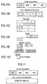
- FIG. 10A to FIG. 10F show hierarchy for encoding formats based on the standard of MPEG Video. Codes of the MPEG Video are assigned to levels of a hierarchical structure as shown in FIG. 10A to FIG. 10F.
- a top level of hierarchy corresponds to a video sequence which is configured by multiple GOPs (an abbreviation for "Group Of Picture"). Each GOP is configured by multiple pictures.
- I picture corresponds to intra-frame codes
- P picture corresponds to interframe codes with respect to a forward direction only
- B picture corresponds to interframe codes with respect to both of forward and backward directions.
- the picture consists of multiple slices corresponding to regions which are determined by partitioning an overall area of the picture. Each slice is configured by multiple macro blocks which are arranged from the right to the left or from the top to the bottom.
- a block of 16 ⁇ 16 dots is divided into blocks of 8 ⁇ 8 dots, which are used for representation of luminance components (i.e., Y1, Y2, Y3 and Y4).
- blocks of 8 ⁇ 8 dots are used for representation of chrominance components (i.e., Cb, Cr) in connection with the region of the luminance components.
- the macro block is constructed by six blocks of 8 ⁇ 8 dots in total. Therefore, the block of 8 ⁇ 8 dots is used as a minimum unit for encoding.
- FIG. 11 shows an example of the hierarchy for encoding formats based on the standard of MPEG Audio. Codes of the MPEG Audio are constructed using "AAU” (an abbreviation for "Audio Access Unit”), which is a minimum unit for encoding.
- AAU an abbreviation for "Audio Access Unit”
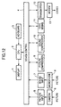
- FIG. 12 is a block diagram showing an example of a sound-picture synchronous compression device which performs synchronous compression and transmission on sounds and pictures.
- a CPU 2 executes programs of a device control block 4 so as to control the device as a whole.
- a user operates a keyboard 3 to input commands and instructions to the device. States of execution of the programs are visually displayed on a screen of a display 1.
- Picture data are taken by a camera 6 and are input to the device by means of a picture input block 5.
- Sound data are created by a microphone 8 and are input to the device by means of a sound input block 7.
- the sound data are subjected to compression by a sound compression block 10.
- the picture data are subjected to compression by a picture compression block 9.
- the compressed sound code corresponding to the compressed sound data as well as the compressed picture code corresponding to the compressed picture data are mixed together using a single code by a code mixing block 11. Then, mixed codes are transmitted onto a transmission line by a transmitter block 12 as well as a modem 13.
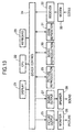
- FIG. 13 is a block diagram showing an example of a sound-picture synchronous reproduction device which performs receiving and synchronous reproduction on sound-picture codes transmitted thereto.
- a CPU 22 executes programs of a device control block 24 to control the device as a whole.
- a user operates a keyboard 23 to input commands and instructions to the device. States of execution of the programs are visually displayed on a screen of a display 21.
- a receiver block 32 receives mixed codes transmitted thereto from a modem 33 as sound codes and picture codes to be reproduced. Then, a code separation block 31 separates the mixed codes into sound codes and picture codes respectively. The sound codes are subjected to expansion (or reproduction) by a sound reproduction block 30. The picture codes are subjected to reproduction by a picture reproduction block 29. Then, contents of picture data corresponding to the reproduced picture codes are visually displayed on a screen of a monitor 26 by a picture output block 25.
- a sound output block 27 provides a speaker 28 with sound data corresponding to the reproduced sound codes. So, the speaker 28 produces the corresponding sounds.
- the aforementioned example of the system for sound-picture compression and reproduction performs communications of codes.
- data processing should be performed in a real-time manner.
- a number of operations (or calculations) are required in processing for the compression and reproduction.
- the conventional system which uses the software for compression and reproduction of sounds and pictures reduces a number of frames representing pictures which are subjected to processing.
- parallel operation instructions of the CPU and DSP are used to perform multiple operations at once, so it is possible to accomplish high-speed performance in the above processing.
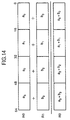
- FIG. 14 shows an example of the parallel operation instructions.
- a 64-bit register R0 stores 4-word values a3, a2, a1 and a0
- a register R1 stores 4-word values b3, b2, b1 and b0.
- Those 4-word values are added together, so addition results are stored in the register R0.
- addition is performed with respect to four words at once, so it is possible to perform high-speed processing.
- Functions of real-time OS can be used for the compression and reproduction of the sounds and pictures.
- the sound processing and picture processing are switched over periodically by a certain period of time, it is possible to perform real-time processing with ease.
- contents of the registers which are presently using should be retained.
- the system performs processings in parallel, which implements the parallel operation instructions requiring "large-bits" registers each having a large number of bits. In that case, the switching of the large-bits registers frequently occurs, so it is impossible to perform high-speed processing. To avoid such a problem, it is necessary to add an additional process which initiates the switching of the processing between the sound compression and picture compression at the appropriate timing so that one of them is selectively performed.
- paper 1 discloses a conventional example of the system which processes sounds and pictures in a synchronized manner.
- the content of the paper 1 is summarized as follows:
- a buffer memory is normally placed in a data accumulated state so that it is normally filled with a certain amount of data or more.
- a reproduction portion of one side always issues a data transfer request, so that data are transferred to reproduction portions of both sides by a unit of a data block.
- paper 2 discloses a conventional example of the system, the content of which is summarized as follows:
- the system checks a difference between a reproduction time of the sound and a reproduction time of the picture. If the sound is delayed from the picture in reproduction, a same screen image is continuously displayed. If the picture is delayed from the sound in reproduction, interpolation is performed with respect to the sound.
- paper 3 discloses a conventional example of the system, the content of which is summarized as follows:
- the system checks a time required for reproduction of one frame. Then, the system sets and processes a picture which should be displayed for a next frame. So, the system reproduces the sound accompanied with the picture.
- the processing of the system is controlled to be suited to the "long" processing whose processing period is long.
- the system after performing the long processing whose processing time is long, the system performs the "short" processing whose processing time is short multiple times by a constant period of time.
- the aforementioned examples of the sound-picture synchronous compression-reproduction system may have a large interval of time for switching over the sound processing and picture processing. In such a case, the system cannot catch up with the timing of execution of the sound processing. In the case where the sound and picture operate in parallel, an overhead for switching over the sound processing and picture processing becomes large. For this reason, the conventional system suffers from a problem that it cannot catch up with the timing of execution of the sound processing, so the reproduction breaks off. In the case where adjustment is performed on the switching timing between the sound processing and picture processing in response to the performance of the CPU and DSP as well as the transmission speed of the communication lines, it is necessary to modify the system with respect to the sound processing and picture processing. In that case, there is a problem that adjustments of the programs take much time.
- the sound-picture synchronous compression-reproduction system is actualized by a sound-picture synchronous compression device and a sound-picture synchronous reproduction device.
- the picture compression process is performed on a designated amount of picture codes. Then, a necessary amount of sound codes is calculated on the basis of a time of the picture compression process and is subjected to sound compression process.
- the device calculates an amount of sound codes for sound compression by which an amount of the compressed sound codes are made greater than the threshold value. Thus, the calculated amount of sound codes is subjected to sound compression process. So, compressed picture codes and compressed sound codes are transmitted to the sound-picture synchronous reproduction device.
- the picture reproduction process is performed on a designated amount of the compressed picture codes. Then, a necessary amount of the compressed sound codes is calculated on the basis of a time of the picture reproduction process and is subjected to sound reproduction process.
- the device calculates an amount of compressed sound codes for sound reproduction by which an amount of the compressed sound codes received are made less than the threshold value. So, the calculated amount of the compressed sound codes is subjected to sound reproduction process.
- the device reproduces the picture codes and sound codes, based on which pictures and sounds are output by the monitor and speaker respectively.
- the picture codes correspond to a number of macro blocks while the sound codes correspond to a number of AAUs.
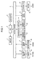
- FIG. 1 shows a configuration of a sound-picture synchronous compression device in accordance with the embodiment of the invention, wherein parts equivalent to those of FIG. 12 are designated by the same numerals.
- the device of FIG. 1 is configured by the device control block 4 for controlling the device as a whole, the CPU 2 for executing programs, the keyboard 3 for inputting commands and instructions given by the user, and the display 1 for visually displaying states of execution of the programs.
- the device of FIG. 1 contains the camera 6 and the picture input block 5 which are used to input pictures as well as the microphone 8 and the sound input block 7 which are used to input sounds.
- the device contains the picture compression block 9 for compressing pictures, the sound compression block 10 for compressing sounds, and the code mixing block 11 for mixing sound codes and picture codes as well as the transmitter block 12 and the modem 13 which are used to perform transmission of codes.
- the device of FIG. 1 further contains a compression control block 14 which controls switching between picture compression and sound compression.
- the sound-picture synchronous compression device of FIG. 1 inputs picture data by means of the picture input block 5 and the camera 6.
- the device inputs sound data by means of the sound input block 7 and the microphone 8.
- the compression control block 14 switches over execution of the picture compression block 9 and execution of the sound compression block 10, so that the picture data and sound data are subjected to compression respectively.
- the picture compression block 9 produces compressed picture codes
- the sound compression block 10 produces compressed sound codes.
- the compressed picture code and compressed sound code are mixed together in a form of a single code by the code mixing block 11. Then, the mixed codes are subjected to transmission by means of the transmitter block 12 and the modem 13.
- FIG. 2 shows a configuration of a sound-picture synchronous reproduction device in accordance with the embodiment of the invention, wherein parts equivalent to those of FIG. 13 are designated by the same numerals.
- the sound-picture synchronous reproduction device of FIG. 2 is configured by the device control block 24 for controlling the device as a whole, the CPU 22 for executing programs, the keyboard 23 for inputting commands and instructions given by the user, and the display 21 for visually displaying states of execution of the programs.
- the device contains the picture output block 25 and the monitor 26 which are used to output pictures as well as the sound output block 27 and the speaker 28 which are used to output sounds.
- the device contains the picture reproduction block 29 for reproducing pictures, the sound reproduction block 30 for reproducing sounds, and the code separation block 31 for separating the mixed codes into sound codes and picture codes as well as the receiver block 32 and the modem 33 which are used to receive the mixed codes transmitted thereto.
- the device of FIG. 2 further contains a reproduction control block 34 which controls switching between picture reproduction and sound reproduction.
- the sound-picture synchronous reproduction device of FIG. 2 receives the mixed codes by means of the receiver block 32 and the modem 33 as sound codes and picture codes which should be reproduced. So, the code separation block 31 separates the mixed codes into the sound codes and picture codes.
- the reproduction control block 34 switches over execution of the picture reproduction block 29 and execution of the sound reproduction block 30, so that the picture codes and sound codes are subjected to reproduction respectively.
- picture data corresponding to the reproduced picture codes are output by means of the picture output block 25 and the monitor 26, while the sound data corresponding to the reproduced sound codes are output by means of the sound output block 27 and the speaker 28.
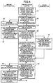
- FIG. 3 shows a sequence of operations for the sound compression and picture compression. Steps of FIG. 3 are classified into three kinds of processings which correspond to the compression control, picture compression and sound compression respectively. So, the steps are arranged in different columns of FIG. 3 respectively.
- step 81 which belongs to the processing of the compression control, the compression control block 14 designates a number of macro blocks or an amount of data (or codes) to call the picture compression block 9.
- the designated number of the macro blocks and the designated amount of the codes are preset values, which are set in advance in such a way that the sound and picture synchronize with each other without causing an break-off event in the sound compression.
- the preset values depend on the system currently used. For example, the preset value can be determined using the unit of line(s).
- step 82 the system of the present embodiment proceeds to step 82, wherein the picture compression block 9 performs picture compression on input picture data.
- step 83 when completing the compressive encoding with respect to the designated number of macro blocks or the designated amount of codes, the picture compression block 9 calls the compression control block 14.
- the compression control block 14 measures a time of the picture compression in step 90. So, in step 84, the compression control block 14 calculates a necessary amount of sound codes based on the measured time of the picture compression so as to call the sound compression block 10. Or, if an amount of sound codes which are compressed but are not subjected to transmission is less than a threshold value, the compression control block 14 calculates a necessary amount of sound codes to call the sound compression block 10.
- step 84 contains two processes which are connected by "OR". Next, a description will be given with respect to the basis of calculations for the necessary amount of sound codes in the latter process described after "OR" in step 84.
- sounds have been already compressed but are remained in a transmission buffer (not shown) of the transmitter block 12 as untransmitted codes.
- a transmission buffer not shown
- the system makes a decision that an amount of the untransmitted codes is less than a prescribed threshold value, it can be assumed that the device has a room for transmission. Therefore, it is possible to conduct a further accumulation of sound codes in the transmission buffer up to a certain value of accumulation which is greater than the threshold value. Therefore, the device performs calculations to produce an amount of sound codes which can be further accumulated to fill up the transmission buffer up to the certain value of accumulation greater than the threshold value. Therefore, in step 84, the compression control block 14 instructs the sound compression block 10 to perform sound compression with respect to the calculated amount of sound codes.
- step 85 which belongs to the processing of the sound compression.
- step 85 when completing compressive encoding with respect to the necessary amount of sound codes which is designated by the sound compression block 10, the sound compression block 10 calls the compression control block 14. So, the system proceeds to step 86 belonging to the processing of the compression control.
- step 86 the compression control block 14 transfers the sound codes and picture codes to the device control block 4, which in turn controls the modem 13 to engage transmission of codes.
- step 87 the compression control block 14 designates a number of macro blocks or an amount of codes so as to transfer control to the picture compression block 9.
- the compression control block 14 designates a number of macro blocks or an amount of codes so as to transfer control to the picture compression block 9. So, the system proceeds to step 88 belonging to the processing of the picture compression. In step 88, the picture compression block 9 continues the picture compression. In step 89, when completing compressive encoding with respect to the designated number of macro blocks or designated amount of codes, the picture compression block 9 calls the compression control block 14.
- the sound-picture synchronous compression device of the present embodiment every time the encoding is performed with respect to a certain region of the picture, a decision is made as to whether the sound compression is performed or not, so that "necessary" sound compression is performed. Thus, it is possible to perform the sound compression and picture compression at a high speed without causing a break-off event of the sound compression.
- FIG. 4 shows a sequence of operations of the sound-picture synchronous reproduction device of FIG. 2. Steps of FIG. 4 are classified into three kinds of processings which correspond to the picture reproduction, reproduction control and sound reproduction. So, the steps are arranged in different columns of FIG. 4 respectively.
- the modem 33 receives codes transmitted thereto, so that the reproduction control block 34 receives sound codes and picture codes from the device control block 24 in step 91.
- the reproduction control block 34 designates a (prescribed) number of macro blocks or an (prescribed) amount of codes to call the picture reproduction block 29.
- the system proceeds to step 93 which belongs to the processing of the picture reproduction.
- the picture reproduction block 29 performs the picture reproduction.
- the picture reproduction block 29 calls the reproduction control block 34. So, the system proceeds to step 95 which belongs to the processing of the reproduction control.
- the reproduction control block 34 measures a reproduction time of the picture in step 100. Then, the system proceeds to step 95. In step 95, the reproduction control block 34 calculates a necessary amount of sound codes based on the reproduction time of the picture so as to call the sound reproduction block 30. Or, if an amount of sound codes which are received but are not reproduced is greater than a threshold value, the reproduction control block 34 calculates a necessary amount of sound codes so as to call the sound reproduction block 30.
- the step 95 contains two processes which are connected by "OR". Next, a description will be given with respect to the basis of calculations for the necessary amount of sound codes in the latter process described after "OR” in step 95.
- a certain amount of sound codes are received but are accumulated in a receiving buffer (not shown) of the receiver block 32 without being subjected to reproduction. If such an amount of "unreproduced” sound codes is greater than a prescribed threshold value, it should be reduced to be less than the threshold value. So, the reproduction control block 34 calculates an amount of sound codes being read from the receiving buffer, by which the amount of unreproduced sound codes is reduced to be less than the threshold value. Therefore, the reproduction control block 34 instructs the sound reproduction block 30 to perform sound reproduction with respect to the calculated amount of sound codes in step 95.
- step 95 the system proceeds to step 96 which belongs to the processing of the sound reproduction.
- step 96 the sound reproduction block 30 performs decoding with respect to the designated amount of sound codes which is designated by the reproduction control block 34; then, the sound reproduction block 30 calls the reproduction control block 34.
- step 97 the reproduction control block 34 designates a number of macro blocks or an amount of codes so as to transfer control to the picture reproduction block 29. Or, if an amount of sound codes which are received but are not reproduced is less than a threshold value, the reproduction control block 34 designates a number of macro blocks or an amount of codes so as to transfer control to the picture reproduction block 29.
- step 98 belongs to the processing of the picture reproduction.
- step 98 the picture reproduction block 29 continues the picture reproduction.
- step 99 when completing decoding with respect to the designated number of macro blocks or the designated amount of codes, the picture reproduction block 29 calls the reproduction control block 34.
- the sound-picture synchronous reproduction device of the present embodiment every time the decoding is performed with respect to a certain region of the picture, a decision is made as to whether to perform the sound reproduction or not, so that "necessary" sound reproduction is performed. Thus, it is possible to perform the sound reproduction and picture reproduction at a high speed without causing a break-off event in the sound reproduction.
- routines representing the compression/reproduction control, picture compression/reproduction and sound compression/reproduction as well as call subroutines, wherein a slash "/" represents "or” so that the compression/reproduction control can be interpreted as the compression control or reproduction control, for example.
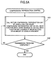
- routines of FIG. 5A are executed by a "compression/reproduction control" unit which corresponds to the aforementioned compression control block or reproduction control block.
- the routines of FIG. 5A and FIG. 5B are designed to switch over the picture processing and sound processing by using the call back function which corresponds to an address of a called subroutine.
- the calling side transfers the address to call the subroutine, in which the call back function is called based on the address.
- FIG. 5A shows a flow of steps with respect to the routine of the compression/reproduction control.
- the compression/reproduction control unit uses a call for a sound compression/reproduction unit as a call back function while using an address of the call back function and a number of macro blocks or an amount of codes as an argument. Using the call back function as well as the argument, the compression/reproduction control unit calls a picture compression/reproduction unit (which corresponds to the aforementioned picture compression block or picture reproduction block).
- a decision is made as to whether the transmission/receiving operation (i.e., transmission operation or receiving operation) completes or not. If the transmission/receiving operation completes, the system ends execution of the routine of the compression/reproduction control shown in FIG. 5A. If not, the system proceeds back to the step 101.
- the transmission/receiving operation i.e., transmission operation or receiving operation
- FIG. 5B shows a flow of steps with respect to the routine of the picture compression/reproduction.
- the picture compression/reproduction unit performs the encoding/decoding operation (i.e., encoding operation or decoding operation) with respect to one macro block.
- a decision is made as to whether the picture compression/reproduction unit completes the encoding/decoding operation with respect to the designated number of macro blocks or the designated amount of codes or not. If the picture compression/reproduction unit does not completes the above encoding/decoding operation, the picture compression/reproduction unit proceeds to step 107. If not, the picture compression/reproduction unit proceeds to step 105 to call the call back function.
- step 106 the picture compression/reproduction unit renews the number of macro blocks or the amount of codes.
- step 107 a decision is made as to whether the picture compression/reproduction unit completes the compression/reproduction operation (i.e., compression operation or reproduction operation) with respect to one frame. If the unit completes the above compression/reproduction operation, the picture compression/reproduction unit reverts control to the original calling side (i.e., compression/reproduction control unit). If not, the picture compression/reproduction unit proceeds back to the step 103.
- the original calling side i.e., compression/reproduction control unit
- the system switches over the picture processing and sound processing by stopping the processing until the issuance of an event which corresponds to a synchronisation control signal of the real-time parallel processing.
- FIG. 6 shows a flow of steps with respect to the routine of the compression/reproduction control.
- the compression/reproduction control unit uses (or designates) a number of macro blocks or an amount of codes as an argument to call the picture compression/reproduction unit.
- the compression/reproduction control unit waits for occurrence of an event given from the picture compression/reproduction unit.
- step 113 a decision is made as to whether the event represents completion of the encoding/decoding operation with respect to the designated number of macro blocks or the designated amount of codes. If the event represents the completion of the above encoding/decoding operation, the compression/reproduction control unit proceeds to step 114 to call the sound compression/reproduction unit which corresponds to the aforementioned sound compression block or sound reproduction block. If not, the compression/reproduction control unit proceeds directly to step 116. After leaving the step 114, the compression/reproduction control unit proceeds to step 115 so as to issue an event representing continuity of the picture compression/reproduction.
- step 116 a decision is made as to whether the event represents completion of the picture compression/reproduction with respect to one frame. If the event represents the completion of the above picture compression/reproduction, the compression/reproduction control unit proceeds to step 117 to make a decision as to whether transmission of codes is completed or not. If not, the compression/reproduction control unit proceeds back to the step 111. If the transmission of the codes is not completed, the compression/reproduction control unit leaves the step 117 to proceed back to the step 111. If the transmission of the codes is completed, the compression/reproduction control unit ends execution of the routine shown in FIG. 6.
- FIG. 7 shows a routine of the picture compression/reproduction.
- the picture compression/reproduction unit performs encoding/decoding operation with respect to one macro block.
- a decision is made as to whether the encoding/decoding operation completes with respect to the designated number of macro blocks or the designated amount of codes. If the picture compression/reproduction unit completes the above encoding/decoding operation, the picture compression/reproduction unit proceeds to step 120 to issue an event representing completion of the encoding/decoding operation. If not, the picture compression/reproduction unit proceeds directly to step 123. After leaving the step 119, the picture compression/reproduction unit proceeds to step 121 to wait for an event representing continuity of the picture compression/reproduction. In step 122, the picture compression/reproduction unit renews the number of macro blocks or the amount of codes.
- step 123 a decision is made as to whether the picture compression/reproduction is completed with respect to one frame or not. If not, the picture compression/reproduction unit leaves the step 123 to proceed back to the step 118. If the above picture compression/reproduction is completed, the picture compression/reproduction unit proceeds to step 124 to issue an event representing completion of the picture compression/reproduction. Then, the picture compression/reproduction unit ends execution of the routine of FIG. 7.
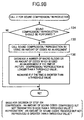
- FIG. 8, FIG. 9A and FIG. 9B are flowcharts showing subroutines which are called during execution of the aforementioned routines.
- FIG. 8 shows a subroutine for the sound compression/reproduction.
- the sound compression/reproduction unit performs the encoding/decoding operation with respect to one AUU.
- step 138 a decision is made as to whether the encoding/decoding operation is completed with respect to the designated amount of codes or not. If not, the sound compression/reproduction unit proceeds back to step 137. If the above encoding/decoding operation is completed, the sound compression/reproduction unit transfers control to the calling side.
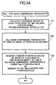
- FIG. 9A shows a subroutine for call 1 of the sound compression/reproduction, which is an example of a call for the sound compression/reproduction.
- the system calculates a necessary amount of sound codes on the basis of a time required for performing the picture compression/reproduction. Using the calculated amount of the sound codes as an argument, the system calls the sound compression/reproduction unit in step 132.
- step 133 if the time required for performing the picture compression/reproduction is longer than a threshold value, the system decreases a number of macro blocks or an amount of codes which is used as an argument. On the other hand, if the time required for performing the picture compression/reproduction is shorter than the threshold value, the system increases a number of macro blocks or an amount of codes which is used as an argument. After completion of the step 133, the system reverts control to the calling side.
- the calculated amount of the sound codes is equivalent to an amount of codes corresponds to a minimum number of AAUs which exceed an amount of sound codes corresponding to a time of 30 ms plus ⁇ .
- a value of ⁇ depends on the performance of the CPU and/or the communication speed.
- the threshold value as well as an increment or a decrement for increasing or decreasing the number of macro blocks or the amount of codes are adjusted in such a way that the sound compression/reproduction processing can be continued without occurrence of a break-off event. They depend on the performance of the CPU and/or the communication speed.
- FIG. 9B shows a subroutine for call 2 of the sound compression/reproduction, which is another example of the call for the sound compression/reproduction or call back function.
- FIG. 9B omits a calculation step like the aforementioned step 131 which should be provided prior to a decision step 134.
- a decision is made in step 134, after the above calculation step, as to whether an amount of sound codes which are compressed but are not subjected to transmission is less than a threshold value or not.
- a decision is made in step 134 as to whether an amount of sound codes which are received but are not subjected to reproduction is greater than a threshold value.
- step 135 the system uses the amount of codes as an argument to call the sound compression/reproduction unit. After leaving the step 135, the system proceeds to step 136.
- the system decreases a number of macro blocks or an amount of codes which is used as an argument.
- the time required for performing the picture compression/reproduction is shorter than a threshold value, the system increases a number of macro blocks or an amount of codes, which is used as an argument.
- the system reverts control to the calling side.
- a calculated amount of sound codes is equivalent to a minimum number of AAUs which exceed a certain amount of sound codes, which is calculated as follows: (Sound codes corresponding to 30 ms) - (remaining sound codes) + ⁇ where a value of ⁇ depends on the performance of the CPU and/or the communication speed.
- the threshold value as well as an increment or a decrement for increasing or decreasing the number of macro blocks or the amount of codes are adjusted in such a way that the sound compression/reproduction processing can be continued without occurrence of a break-off event. They depend on the performance of the CPU and/or the communication speed.
- This invention is designed to reduce the overhead at the switching of the parallel operation registers, so it is possible to perform the sound compression/reproduction and picture compression/reproduction at a high speed.
- the switching is performed by an interval of time which is selected in such a way that the sound processing does not break off.
- different modules which separate from each other are used for the sound compression/reproduction and picture compression/reproduction respectively. So, even if a change occurs on the performance of the CPU and/or the communication speed, it is possible to adjust the switching timing with ease.
Landscapes
- Engineering & Computer Science (AREA)
- Multimedia (AREA)
- Signal Processing (AREA)
- Television Signal Processing For Recording (AREA)
- Compression Or Coding Systems Of Tv Signals (AREA)
- Indexing, Searching, Synchronizing, And The Amount Of Synchronization Travel Of Record Carriers (AREA)
Applications Claiming Priority (3)
| Application Number | Priority Date | Filing Date | Title |
|---|---|---|---|
| JP27140/97 | 1997-02-12 | ||
| JP2714097 | 1997-02-12 | ||
| JP9027140A JP3000949B2 (ja) | 1997-02-12 | 1997-02-12 | 音声・画像同期圧縮再生装置及びその方法 |
Publications (2)
| Publication Number | Publication Date |
|---|---|
| EP0859512A2 true EP0859512A2 (de) | 1998-08-19 |
| EP0859512A3 EP0859512A3 (de) | 2005-01-05 |
Family
ID=12212753
Family Applications (1)
| Application Number | Title | Priority Date | Filing Date |
|---|---|---|---|
| EP98102256A Ceased EP0859512A3 (de) | 1997-02-12 | 1998-02-10 | Synchronisierte Ton-Bild Kompression und synchronisiertes Wiedergabesystem |
Country Status (3)
| Country | Link |
|---|---|
| US (2) | US6104756A (de) |
| EP (1) | EP0859512A3 (de) |
| JP (1) | JP3000949B2 (de) |
Families Citing this family (3)
| Publication number | Priority date | Publication date | Assignee | Title |
|---|---|---|---|---|
| JP3000949B2 (ja) * | 1997-02-12 | 2000-01-17 | 日本電気株式会社 | 音声・画像同期圧縮再生装置及びその方法 |
| JP4098420B2 (ja) * | 1998-11-04 | 2008-06-11 | 富士通株式会社 | 音響データ・動画データの同期再構築方法及び装置 |
| JP4407472B2 (ja) * | 2004-10-29 | 2010-02-03 | ソニー株式会社 | 符号化及び復号装置並びに符号化及び復号方法 |
Family Cites Families (11)
| Publication number | Priority date | Publication date | Assignee | Title |
|---|---|---|---|---|
| CA2107727C (en) * | 1992-10-07 | 1999-06-01 | Hiroaki Ueda | Synchronous compression and reconstruction system |
| US5481543A (en) * | 1993-03-16 | 1996-01-02 | Sony Corporation | Rational input buffer arrangements for auxiliary information in video and audio signal processing systems |
| JPH0764730A (ja) * | 1993-08-31 | 1995-03-10 | Victor Co Of Japan Ltd | 画像・音声データの転送方法 |
| JP3075034B2 (ja) * | 1993-09-02 | 2000-08-07 | 日本電気株式会社 | 画像・音声復号化装置 |
| US5467139A (en) * | 1993-09-30 | 1995-11-14 | Thomson Consumer Electronics, Inc. | Muting apparatus for a compressed audio/video signal receiver |
| JPH07110756A (ja) * | 1993-10-14 | 1995-04-25 | Matsushita Electric Ind Co Ltd | 動画音声同期制御装置 |
| JP3521461B2 (ja) * | 1993-12-24 | 2004-04-19 | カシオ計算機株式会社 | 複数の周期的なメディアデータの処理装置 |
| US5583652A (en) * | 1994-04-28 | 1996-12-10 | International Business Machines Corporation | Synchronized, variable-speed playback of digitally recorded audio and video |
| US5784572A (en) * | 1995-12-29 | 1998-07-21 | Lsi Logic Corporation | Method and apparatus for compressing video and voice signals according to different standards |
| JPH09205618A (ja) * | 1996-01-29 | 1997-08-05 | Mitsubishi Electric Corp | 動画像音声伸張再生装置および動画像音声同期制御器 |
| JP3000949B2 (ja) * | 1997-02-12 | 2000-01-17 | 日本電気株式会社 | 音声・画像同期圧縮再生装置及びその方法 |
-
1997
- 1997-02-12 JP JP9027140A patent/JP3000949B2/ja not_active Expired - Fee Related
-
1998
- 1998-02-10 EP EP98102256A patent/EP0859512A3/de not_active Ceased
- 1998-02-12 US US09/022,540 patent/US6104756A/en not_active Expired - Lifetime
-
2000
- 2000-06-09 US US09/591,150 patent/US6269119B1/en not_active Expired - Lifetime
Non-Patent Citations (2)
| Title |
|---|
| FOLEY P ED - INSTITUTE OF ELECTRICAL AND ELECTRONICS ENGINEERS: "The Mpact media processor redefines the multimedia PC" DIGEST OF PAPERS OF COMPCON (COMPUTER SOCIETY CONFERENCE) 1996 TECHNOLOGIES FOR THE INFORMATION SUPERHIGHWAY. SANTA CLARA, FEB. 25 - 28, 1996, DIGEST OF PAPERS OF THE COMPUTER SOCIETY COMPUTER CONFERENCE COMPCON, LOS ALAMITOS, IEEE COMP. SOC. PRESS,, vol. CONF. 41, 25 February 1996 (1996-02-25), pages 311-318, XP010160915 ISBN: 0-8186-7414-8 * |
| RATHNAM S ET AL: "An architectural overview of the programmable multimedia processor, TM-1" DIGEST OF PAPERS OF COMPCON (COMPUTER SOCIETY CONFERENCE) 1996 TECHNOLOGIES FOR THE INFORMATION SUPERHIGHWAY. SANTA CLARA, FEB. 25 - 28, 1996, DIGEST OF PAPERS OF THE COMPUTER SOCIETY COMPUTER CONFERENCE COMPCON, LOS ALAMITOS, IEEE COMP. SOC. PRESS,, vol. CONF. 41, 25 February 1996 (1996-02-25), pages 319-326, XP010160916 ISBN: 0-8186-7414-8 * |
Also Published As
| Publication number | Publication date |
|---|---|
| US6104756A (en) | 2000-08-15 |
| JPH10224740A (ja) | 1998-08-21 |
| US6269119B1 (en) | 2001-07-31 |
| EP0859512A3 (de) | 2005-01-05 |
| JP3000949B2 (ja) | 2000-01-17 |
Similar Documents
| Publication | Publication Date | Title |
|---|---|---|
| US5488695A (en) | Video peripheral board in expansion slot independently exercising as bus master control over system bus in order to relief control of host computer | |
| US5602592A (en) | Moving picture compressed signal changeover apparatus | |
| JP3630590B2 (ja) | 復号化装置及び伝送システム | |
| JP2001514826A (ja) | 静止画像の送信と表示の方法と装置 | |
| JPH10117353A (ja) | データ処理装置および受信装置 | |
| US6141709A (en) | Peripheral circuitry for providing video I/O capabilities to a general purpose host computer | |
| CA2160562A1 (en) | Adaptive video decompression | |
| JP2008500752A (ja) | ビデオデータの適応型復号 | |
| US6104756A (en) | Sound-picture synchronous compression and synchronous reproduction system | |
| US6751404B1 (en) | Method and apparatus for detecting processor congestion during audio and video decode | |
| JPH11146398A (ja) | マルチメディア情報処理装置 | |
| JP3159098B2 (ja) | 画像と音声の同期再生装置 | |
| EP0634726B1 (de) | Vorrichtung für die inverse diskrete Cosinustransformation | |
| CN112995596A (zh) | 全景视频传输方法、装置、电子设备和存储介质 | |
| US6885703B1 (en) | Video code processing method, which can generate continuous moving pictures | |
| JP7679462B2 (ja) | 動画像受信装置、動画像送信装置、動画像送受信システム、制御方法及びプログラム | |
| JPH06350983A (ja) | 画像信号用可変レート符号化装置および復号化装置 | |
| JP2001128165A (ja) | 映像信号切替え装置及びその映像信号切替え方式 | |
| JP3512716B2 (ja) | 連続a/vデータの転送システム及び転送方法 | |
| JP2007281716A (ja) | 無線動画伝送システム、無線動画伝送方法、無線動画送信装置、無線動画送信方法、そのコンピュータプログラム、無線動画受信装置、無線動画受信方法、並びにそのコンピュータプログラム | |
| JP2011107246A (ja) | 動画像再生装置及び動画像再生方法並びにプログラム | |
| JP2998640B2 (ja) | 動画像再生装置 | |
| JP2006121578A (ja) | 画像伝送システム、画像送信装置、画像受信装置および画像伝送方法 | |
| JP2002335528A (ja) | 動画像復号化装置及び方法 | |
| JP3860674B2 (ja) | 多重通信装置、多重通信方法、および多重通信プログラムを記録した媒体 |
Legal Events
| Date | Code | Title | Description |
|---|---|---|---|
| PUAI | Public reference made under article 153(3) epc to a published international application that has entered the european phase |
Free format text: ORIGINAL CODE: 0009012 |
|
| AK | Designated contracting states |
Kind code of ref document: A2 Designated state(s): AT BE CH DE DK ES FI FR GB GR IE IT LI LU MC NL PT SE |
|
| AX | Request for extension of the european patent |
Free format text: AL;LT;LV;MK;RO;SI |
|
| PUAL | Search report despatched |
Free format text: ORIGINAL CODE: 0009013 |
|
| AK | Designated contracting states |
Kind code of ref document: A3 Designated state(s): AT BE CH DE DK ES FI FR GB GR IE IT LI LU MC NL PT SE |
|
| AX | Request for extension of the european patent |
Extension state: AL LT LV MK RO SI |
|
| 17P | Request for examination filed |
Effective date: 20050630 |
|
| AKX | Designation fees paid |
Designated state(s): DE FR GB NL |
|
| 17Q | First examination report despatched |
Effective date: 20070918 |
|
| RAP1 | Party data changed (applicant data changed or rights of an application transferred) |
Owner name: ACER INCORPORATED |
|
| STAA | Information on the status of an ep patent application or granted ep patent |
Free format text: STATUS: THE APPLICATION HAS BEEN REFUSED |
|
| 18R | Application refused |
Effective date: 20091208 |