EP0859536A1 - Infrarot-Strahler und dessen Verwendung - Google Patents
Infrarot-Strahler und dessen Verwendung Download PDFInfo
- Publication number
- EP0859536A1 EP0859536A1 EP97102460A EP97102460A EP0859536A1 EP 0859536 A1 EP0859536 A1 EP 0859536A1 EP 97102460 A EP97102460 A EP 97102460A EP 97102460 A EP97102460 A EP 97102460A EP 0859536 A1 EP0859536 A1 EP 0859536A1
- Authority
- EP
- European Patent Office
- Prior art keywords
- infrared
- infrared radiator
- protective layer
- metal
- black
- Prior art date
- Legal status (The legal status is an assumption and is not a legal conclusion. Google has not performed a legal analysis and makes no representation as to the accuracy of the status listed.)
- Granted
Links
Images


Classifications
-
- H—ELECTRICITY
- H05—ELECTRIC TECHNIQUES NOT OTHERWISE PROVIDED FOR
- H05B—ELECTRIC HEATING; ELECTRIC LIGHT SOURCES NOT OTHERWISE PROVIDED FOR; CIRCUIT ARRANGEMENTS FOR ELECTRIC LIGHT SOURCES, IN GENERAL
- H05B3/00—Ohmic-resistance heating
- H05B3/10—Heating elements characterised by the composition or nature of the materials or by the arrangement of the conductor
- H05B3/12—Heating elements characterised by the composition or nature of the materials or by the arrangement of the conductor characterised by the composition or nature of the conductive material
- H05B3/14—Heating elements characterised by the composition or nature of the materials or by the arrangement of the conductor characterised by the composition or nature of the conductive material the material being non-metallic
-
- G—PHYSICS
- G01—MEASURING; TESTING
- G01J—MEASUREMENT OF INTENSITY, VELOCITY, SPECTRAL CONTENT, POLARISATION, PHASE OR PULSE CHARACTERISTICS OF INFRARED, VISIBLE OR ULTRAVIOLET LIGHT; COLORIMETRY; RADIATION PYROMETRY
- G01J3/00—Spectrometry; Spectrophotometry; Monochromators; Measuring colours
- G01J3/02—Details
- G01J3/10—Arrangements of light sources specially adapted for spectrometry or colorimetry
- G01J3/108—Arrangements of light sources specially adapted for spectrometry or colorimetry for measurement in the infrared range
-
- G—PHYSICS
- G01—MEASURING; TESTING
- G01N—INVESTIGATING OR ANALYSING MATERIALS BY DETERMINING THEIR CHEMICAL OR PHYSICAL PROPERTIES
- G01N21/00—Investigating or analysing materials by the use of optical means, i.e. using sub-millimetre waves, infrared, visible or ultraviolet light
- G01N21/17—Systems in which incident light is modified in accordance with the properties of the material investigated
- G01N21/1702—Systems in which incident light is modified in accordance with the properties of the material investigated with opto-acoustic detection, e.g. for gases or analysing solids
-
- H—ELECTRICITY
- H05—ELECTRIC TECHNIQUES NOT OTHERWISE PROVIDED FOR
- H05B—ELECTRIC HEATING; ELECTRIC LIGHT SOURCES NOT OTHERWISE PROVIDED FOR; CIRCUIT ARRANGEMENTS FOR ELECTRIC LIGHT SOURCES, IN GENERAL
- H05B3/00—Ohmic-resistance heating
- H05B3/20—Heating elements having extended surface area substantially in a two-dimensional [2D] plane, e.g. plate-heater
- H05B3/22—Heating elements having extended surface area substantially in a two-dimensional [2D] plane, e.g. plate-heater non-flexible
- H05B3/26—Heating elements having extended surface area substantially in a two-dimensional [2D] plane, e.g. plate-heater non-flexible heating conductor mounted on insulating base
-
- H—ELECTRICITY
- H05—ELECTRIC TECHNIQUES NOT OTHERWISE PROVIDED FOR
- H05B—ELECTRIC HEATING; ELECTRIC LIGHT SOURCES NOT OTHERWISE PROVIDED FOR; CIRCUIT ARRANGEMENTS FOR ELECTRIC LIGHT SOURCES, IN GENERAL
- H05B2203/00—Aspects relating to Ohmic resistive heating covered by group H05B3/00
- H05B2203/002—Heaters using a particular layout for the resistive material or resistive elements
- H05B2203/003—Heaters using a particular layout for the resistive material or resistive elements using serpentine layout
-
- H—ELECTRICITY
- H05—ELECTRIC TECHNIQUES NOT OTHERWISE PROVIDED FOR
- H05B—ELECTRIC HEATING; ELECTRIC LIGHT SOURCES NOT OTHERWISE PROVIDED FOR; CIRCUIT ARRANGEMENTS FOR ELECTRIC LIGHT SOURCES, IN GENERAL
- H05B2203/00—Aspects relating to Ohmic resistive heating covered by group H05B3/00
- H05B2203/011—Heaters using laterally extending conductive material as connecting means
-
- H—ELECTRICITY
- H05—ELECTRIC TECHNIQUES NOT OTHERWISE PROVIDED FOR
- H05B—ELECTRIC HEATING; ELECTRIC LIGHT SOURCES NOT OTHERWISE PROVIDED FOR; CIRCUIT ARRANGEMENTS FOR ELECTRIC LIGHT SOURCES, IN GENERAL
- H05B2203/00—Aspects relating to Ohmic resistive heating covered by group H05B3/00
- H05B2203/017—Manufacturing methods or apparatus for heaters
-
- H—ELECTRICITY
- H05—ELECTRIC TECHNIQUES NOT OTHERWISE PROVIDED FOR
- H05B—ELECTRIC HEATING; ELECTRIC LIGHT SOURCES NOT OTHERWISE PROVIDED FOR; CIRCUIT ARRANGEMENTS FOR ELECTRIC LIGHT SOURCES, IN GENERAL
- H05B2203/00—Aspects relating to Ohmic resistive heating covered by group H05B3/00
- H05B2203/032—Heaters specially adapted for heating by radiation heating
Definitions
- the invention relates to an infrared radiator made of a metal black and its Use in gas sensors.
- Black radiators or Planckian radiators are generally known from physics. she are characterized by the fact that their absorption is equal to their emissivity if they are in thermal equilibrium. So a good absorber is also a good emitter and ever the higher the absorption of a radiator material, the higher the emissivity of the same. According to Planck, the emitted spectrum is determined by the temperature of the radiator, and the maximum of the spectrum shifts in when the radiator is heated or heated Direction of the shorter wavelengths. For radiation in the infrared range of 1-10 The black body temperature is, for example, a few hundred Kelvin.
- Metal-Black such as platinum black, gold black, nickel black or Chrome black
- This material consists of a variety of Metal particles that are loosely connected like a sponge or so-called colloidal are distributed.
- the individual particles are of submicroscopic size and have typically a diameter of 2 to 20 nanometers.
- the loose distribution of the Metal particles shows that the total surface area per unit volume or the specific Surface, the metal black is very large.
- Optical radiation incident on the metal black is reflected and absorbed many times on the surfaces of the individual particles before they emerges from the material into the free space again. Owing to the multiple absorption they then only a very small portion of their original energy. The radiation “loses itself "in the sponge-like metal.
- the specific surface is therefore considered to be Measure of the absorption of the material.
- the specific surface area of a platinum black is for example 30 square meters per gram, being 90 to 95% of the incident radiation absorbed.
- Platinum black can be applied in the form of a thin layer by electrochemical deposition to an electrically conductive surface, for example made of platinum or a platinum alloy.
- an electrically conductive surface for example made of platinum or a platinum alloy.
- Such a platinum black layer acts as a good infrared absorber and emitter with an absorption at room temperature of more than 90% in the wavelength range from 2 to 20 micrometers.
- the platinum surface is heated in order to achieve radiation from the platinum black in the range from 2 to 20 micrometers, this becomes thermodynamically unstable.
- the heating causes the individual platinum particles to migrate and sinter together and thus to reduce the specific surface area of the platinum black. For example, heating to 260 ° C for 40 minutes results in a reduction in the specific surface area by half (Khassan et al., Russian Journal of Physical Chemistry 42 (10), 1968, p. 1324).
- Infrared emitters based on metal black are not known from the prior art.
- good absorbers in the wavelength range below 1 micron are below the Known designation cermet.
- an infrared radiator based on a metal black to realize the absorption and when heated for a long time Emissivity is maintained
- the infrared heater is intended to be thermodynamic and be chemically stable, i.e. resistant to heat and oxidation.
- the infrared emitter is supposed to also in the form of one or more thin layers on the entire surface of one Wafers can be produced by sawing into a variety of individual infrared emitters smaller Flat can be dismantled.
- the object is achieved by an infrared radiator which has a heater and a layer of a metal black arranged thereon, which with a Protective layer is provided, which covers the metal particles of the metal black.
- the Protective layer causes absorption and absorption even when the infrared heater is heated Emission of the emitter is maintained over a long period of time.
- the protective layer is especially heat-resistant and insoluble in water and in dilute acids and bases. It is largely transparent to the emitted radiation and protects the metal particles Oxidation and reduces sintering together of the metal particles when heated.
- a metal black without a protective layer has a very high surface energy that warmed up at home Metal-Black contributes significantly to the sintering together of the metal particles. A reduction This surface energy reduces the sintering of the particles, which means the size of the entire absorbent surface of the emitter and its emissivity is maintained.
- Suitable protective layers are all oxides, nitrides, silicides, carbides and borides, which are heat-resistant and, for use in normal ambient air, insoluble in water and dilute acids and bases. These materials include, for example, Al 2 O 3 , SiO 2 , ZrO 2 , PtSi, SiC, TiC, TiB 2 , Si 3 N 4 , W 2 C, MgO, HfO 2 , and TiN and combinations of these materials. Most of these materials can be applied to the metal black by chemical vapor deposition (CVD) or by thermal vapor deposition. With the exception of SiO 2, their melting points are above 2000 ° C, the melting point of TiC above 3000 ° C. Other methods of applying the protective layer are sputtering or deposition from a solution. The layer thickness is selected depending on the material and the desired emitted wavelength so that the layer has an acceptable transparency.
- a preferred infrared radiator consists of a heater on which a layer of platinum black is arranged, the metal particles of which are covered by a layer of Al 2 O 3 . Photographs of the coated metal black with the electron microscope show that the sponge-like structure of the material is preserved during the production of the protective layer.
- the thickness of the protective layer is at least 10 nm, at most 10 micrometers, a layer thickness of 200 nm being easily achievable using the methods mentioned above.
- a protective layer with a minimum thickness of 10 nm provides the necessary protection against heat, sintering and oxidation when heated to 800 ° C for several days.
- the infrared radiator as a modulated light source, its thermal mass is also taken into account when choosing the thickness of the protective layer.
- an infrared radiator with a protective layer of 0.2 micrometers allows the heating to be modulated up to 30 Hz with a resulting modulation depth of 90%.
- the thickness of the protective layer is also selected in accordance with the desired transparency of the protective layer in the spectral range of the emitted radiation; the thinner the protective layer, the higher the transparency.
- metal blacks are also suitable for an infrared heater such as for example metal black based on silver, gold, palladium, rhodium, iridium, Ruthenium, osmium, nickel, copper and mixtures of the metals listed here.
- Figure 1 a shows a greatly enlarged cross section through a first embodiment of the Infrared emitter according to the invention realized on a silicon wafer.
- Figure 1 b shows a top view of the heater for the infrared radiator.
- FIGS. 2 a) and b) show the first embodiment of the infrared radiator according to the invention realized on a standard header.
- FIGS. 3 a) and b) show an enlarged version of a second infrared emitter on a plastic film.
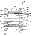
- FIG. 4 shows the infrared radiator according to the invention in use in one optoacoustic gas sensor.
- the infrared radiator 1 in FIG. 1 a) has a monolithic structure and has a piece of a silicon wafer 2, a membrane 3, a heater 4 and a layer of metal black 5 with a protective layer 6.
- a thin layer 3 of, for example, Si 3 N 4 or SiO x N y is arranged on the upper surface of the silicon wafer 2.
- the silicon wafer 2 is selectively under-etched from its lower side to the thin layer 3.
- the silicon wafer thus has an opening 7, over which the thin layer 3 lies like a membrane 3.
- a heater 4 is arranged on the membrane 3.
- the heater 4 in FIG. 1 b) consists, for example, of a thin-layered meander made of platinum, which has been applied to the thin layer 3 by means of vapor deposition and a mask.
- the membrane 3 is indicated with a broken line.
- contact electrodes 8 for applying a heating voltage.
- the width of the individual tracks of the meander are chosen so that a desired temperature of the platinum is achieved when the heating voltage is applied. For this purpose, they are arranged as narrowly as possible and as close as possible to one another in order to achieve regular heating of the entire surface of the radiator.
- the meander of the heater 4 protrudes beyond the surface of the diaphragm 3 indicated by the broken line, so that part of the meander lies above the silicon wafer 2. In the case of modulated heating operation, this arrangement aims at rapid cooling between the voltage pulses and a good modulation depth of the emitted radiation.
- the heating layer 4 On top of the heating layer 4 there is a layer 5 of metal black with a protective layer 6 which, when heated to a temperature of 300 ° C., emits radiation, the maximum of which is at a wavelength of 4.3 micrometers. If the heating layer 4 is heated to 800 ° C., the maximum of the emitted radiation is at a wavelength of 2.7 micrometers.
- This version of the infrared emitter is particularly suitable for use in small systems.
- the dimensions of the radiator are, for example, 6 x 6 mm 2 , but they can only be up to 0.5 x 0.5 mm 2 .
- the monolithic structure of the radiator allows integration in systems with a similar monolithic structure, such as optical sensors for medicine, chemistry, etc.
- the infrared radiator in this embodiment can be produced in a batch production by means of masks in a large number on a wafer, which follows Completion is sawn into individual emitters.
- the protective layer 6 is applied to the metal black by various methods of thin-film technology. Thermal vapor deposition and chemical vapor deposition are best suited for the application of Al 2 O 3 and SiO 2 , with sputtering under vacuum and deposition from a solution also being suitable for other materials.
- FIG 2a is a single infrared radiator 1 of the first embodiment in Figure 1 on one Standard header 9 with electrodes 10 mounted for applying the heating voltage.
- a pyrosensor 11 and an amplifier circuit 12 with a JFET and a High ohm resistor arranged.
- the pyro sensor 11 is used for the control measurement of the emitted infrared radiation. Part of the radiation emitted is on the inner walls and the window 13 of the header housing diffusely scattered, part of which in turn on the Pyrosensor 11 falls.
- the signal generated and amplified by the pyro sensor then gives one Relative value of the total radiation.
- the window 13 consists of a broadband infrared transparent Material, such as glass or silicon, or from a narrow-band infrared filter, such as a bandpass filter or transparent at a given wavelength an electrically controlled variable bandpass filter.
- the infrared radiator 1 is made on a thick film substrate Aluminum oxide or other ceramics mounted and with external connecting legs the heating voltage contacted.
- FIG. 3 a shows a second embodiment of the infrared radiator 1 in a top view.
- She is the one in Similar to Figure 1, but instead of a silicon wafer has a film 14 consisting of Kapton, a polymid, or other temperature-resistant plastic.
- a heating layer 4 which by means of screen printing and an electrically conductive paste on the Foil 14 has been applied.
- the heating layer is a coherent one Surface.
- On the heater 4 is a layer applied by electrochemical deposition Metal-Black 5 arranged with the protective layer 6.
- Figure 3 b shows the radiator in cross section with contact electrodes 15 for applying a voltage to the heater 4.
- a frame 16 is arranged, through which the contact electrodes 15 are attached to the film 14.
- This version of the spotlight is particularly suitable for spotlights with a larger area. Its dimensions are, for example, 10 x 10 mm 2 , but can be up to a multiple of this size.
- Infrared emitters of this type can be used as optical sources alone or in optical devices such as Sensors, analyzers and used in spectroscopy.
- a special one The use of the radiator is in the field of optoacoustic gas sensors. This consist essentially of a gas measuring cell, a microphone and an optical source. This sends pulses of light from the wavelength into the measuring cell, from that to detecting gas is absorbed. If there is gas in the measuring cell, it absorbs it incident radiation, heats up and expands as a result. The through this Expansion caused by pressure fluctuations in the measuring cell is received by the microphone and evaluated by an evaluation circuit.
- the optical light source consists of a light bulb and an optical bandpass filter.
- the aim is to make the gas sensor as small as possible.
- a gas sensor from WO 96/24831 is known, which is made of silicon wafers is constructed. With this sensor, a light bulb as a light source would be much larger than the sensor itself.
- the infrared radiator is in one wafer-based optoacoustic gas sensor used.
- FIG. 4 shows a monolithic structure of an optoacoustic gas sensor (41) Integrated infrared radiator according to the invention. It has an infrared radiator 1 the same that in Figure 1 with a piece of a silicon wafer 2 and a membrane 3 on which the Heater 4 and the metal black 5 with protective layer 6 are arranged.
- a silicon wafer 20 is arranged as a spacer, one in the middle Opening 71 has a free volume 71 which has been brought about by etching through.
- the radiant metal black 5 with protective layer 6 is enclosed by this opening Silicon wafer 20.
- On one side of silicon wafer 20 is a thin layer of silicon etched away, whereby an opening 21 is formed during the further construction of the sensor.
- An optical bandpass filter which consists of a first filter, is arranged on the silicon wafer 20 22, a filter substrate 23 and a second filter 24, the filters 22 and 24 contain several thin layers.
- the opening 21 to the free volume 71 above the Infrared heater 1 serves to equalize the pressure, since otherwise the pressure builds up in volume 71 Load connections between the optical bandpass filter and the silicon wafer 20 would.
- the measuring cell and the are on the second filter 24 of the optical bandpass filter Microphone of the optoacoustic gas sensor arranged.
- the measuring cell consists of a Silicon wafer 25 similar to wafers 2 and 20.
- Wafer 25 is partially undercut, so that it forms a free volume, the gas measuring cell 26, that of the filter 24 and a thin one the undercut remaining silicon layer 29 is limited.
- the silicon wafer 25 has two openings 27 and 28.
- the first opening 27 serves to admit gases into the Gas measuring cell 26.
- the second opening 28 leads to the microphone 40 consisting of a stationary and a movable electrode on another silicon wafer are arranged.
- the microphone 40 is constructed from the silicon wafer 30, which is the same as that Wafer 2 has a thin layer 31, for example made of silicon nitride.
- a free volume 32 was formed, which is characterized by the thin, Membrane-same layer 31 is limited.
- the movable electrode 33 is on the layer 31 arranged the microphone.
- Monolithic construction can be carried out in a batch fabrication in every production run manufacture a large number of optoacoustic gas sensors of this type.
- the Components infrared emitter 1, spacer 20, optical bandpass filter 22-24, measuring cell 26 and the microphone 40 first manufactured in a plurality on a wafer, glued together and finally sawn into individual gas sensors.
- a second use of the infrared emitter is in the field of gas sensors after Transmitted light principle. These have an infrared source, an infrared filter, a gas measuring cell and a detector on the intensity changes due to absorption by the Measures gas in the measuring cell.
- the infrared emitter according to the invention is small due to its small size Size particularly suitable.
- the infrared emitter is in the field of visible Incandescent lamps in a vacuum.
- that is Heater material heated to a higher temperature and as a protective layer on the metal black used a material with a higher melting point.
- TiC is also suitable for this a melting point of 3067 ° C.
- Materials are used for the metal black in this application such as titanium, zircon, hafnium, vanadium, tantalum, niobium, chromium, nickel, Molybdenum, tungsten, rhenium or mixtures of these materials are suitable. With these Materials achieve emissions in the wavelength range from 0.3 to 5 micrometers.
Landscapes
- Physics & Mathematics (AREA)
- Spectroscopy & Molecular Physics (AREA)
- General Physics & Mathematics (AREA)
- Analytical Chemistry (AREA)
- Life Sciences & Earth Sciences (AREA)
- Chemical & Material Sciences (AREA)
- Health & Medical Sciences (AREA)
- Biochemistry (AREA)
- General Health & Medical Sciences (AREA)
- Immunology (AREA)
- Pathology (AREA)
- Photometry And Measurement Of Optical Pulse Characteristics (AREA)
- Investigating Or Analysing Materials By Optical Means (AREA)
- Inspection Of Paper Currency And Valuable Securities (AREA)
- Closed-Circuit Television Systems (AREA)
Abstract
Description
Claims (20)
- Infrarot-Strahler (1) mit einer Heizung (4) und einer Schicht aus einem Metal-Black (5) bestehend aus kolloidal verteilten Metallpartikeln, dadurch gekennzeichnet dass das Metal-Black (5) eine thermisch stabile Schutzschicht (6) aufweist, welche die Metallpartikel des Metal-Black (5) bedeckt.
- Infrarot-Strahler (1) nach Anspruch 1, dadurch gekennzeichnet, dass die Schutzschicht (6) eines oder mehrere der Materialien Oxid, Nitrid, Borid, Silizid oder Carbid enthält.
- Infrarot-Strahler (1) nach Anspruch 2, dadurch gekennzeichnet, dass das Metal-Black (5) eines oder mehrere der Metalle Platin, Silber, Gold, Palladium, Rhodium, Iridium, Ruthenium, Osmium, Titan, Zirkon, Hafnium, Vanadium, Tantal, Niob, Chrom, Nickel, Kupfer, Molybdän, Wolfram oder Rhenium enthält.
- Infrarot-Strahler (1) nach Anspruch 3, dadurch gekennzeichnet, dass die Schutzschicht (6) eine Dicke zwischen 10 Nanometern und 10 Mikrometern aufweist
- Infrarot-Strahler (1) nach Anspruch 4, dadurch gekennzeichnet, dass der Infrarot-Strahler (1) monolithisch aufgebaut ist, indem die Heizung (4) des Infrarot-Strahlers (1) als dünne Schicht (4) auf einer über einer Öffnung (7) eines unterätzten Silizium-Wafers (2) liegenden Membran (3) angeordnet ist und das Metal-Black (5) mit der Schutzschicht (6) auf der Heizung (4) liegt.
- Infrarot-Strahler (1) nach Anspruch 5, dadurch gekennzeichnet, dass mindestens ein Infrarot-Strahler (1) auf einem Standard-Header (9) oder auf einem Dickfilmsubstrat montiert ist.
- Infrarot-Strahler (1) nach Anspruch 6, dadurch gekennzeichnet, dass neben dem Infrarot-Strahler (1) ein Pyrosensor (11) mit einer Verstärkerschaltung (12) zur Messung eines Teils der emittierten Strahlung angeordnet ist.
- Infrarot-Strahler (1) nach Anspruch 6 oder 7, dadurch gekennzeichnet, dass über dem Standard-Header (9) oder dem Dickfilmsubstrat ein Fenster (13) angeordnet ist, das aus einem Bandpassfilter oder einem variablen Bandpassfilter besteht.
- Infrarot-Strahler (1) nach Anspruch 4, dadurch gekennzeichnet, dass der Infrarot-Strähler (1) auf einer Folie (14) aus einem temperaturbeständigen Kunststoff angeordnet ist.
- Infrarot-Strahler (1) nach Anspruch 9, dadurch gekennzeichnet, dass neben dem Infrarot-Strahler (1) ein Pyrosensor (11) mit einer Verstärkerschaltung (12) zur Messung eines Teils der emittierten Strahlung angeordnet ist.
- Infrarot-Strahler (1) nach einem der Ansprüche 5-10, dadurch gekennzeichnet, dass die Schutzschicht (6) beständig gegen Oxidation, Wasser und verdünnte Säuren und Basen ist.
- Infrarot-Strahler (1) nach einem der Ansprüche 4-11, dadurch gekennzeichnet, dass die Schutzschicht (6) eines der Materialien Al2O3, SiO2 oder TiC enthält.
- Infrarot-Strahler (1) nach einem der Ansprüche 4-12, dadurch gekennzeichnet, dass die Heizung (4) aus einer Platinlegierung besteht.
- Infrarot-Strahler (1) nach einem der Ansprüche 4-13, dadurch gekennzeichnet, dass die Heizung (4) in der Form eines Mäanders ausgelegt ist, das Mäander über die Breite der Öffnung (7) hinausreicht und dessen Bögen über dem Silizium-Wafer (2) liegen.
- Verfahren zur Herstellung eines Infrarot-Strahlers (1) nach Anspruch 4, dadurch gekennzeichnet, dass die Schutzschicht (6) durch thermisches Aufdampfen, Sputtern, chemical vapor deposition oder chemisches Abscheiden aus einer Lösung auf das Metal-Black (5) aufgebracht wird.
- Verwendung eines Infrarot-Strahlers (1) nach einem der Ansprüche 4-14 in einem Gassensor nach dem Durchlichtprinzip.
- Verwendung eines Infrarot-Strahlers (1) nach einem der Ansprüche 4-14 in einem optoakustischen Gassensor.
- Verwendung eines Infrarot-Strahlers (1) nach Anspruch 17, dadurch gekennzeichnet, dass der optoakustische Gassensor monolithisch aus Silizium-Wafern aufgebaut ist.
- Verwendung eines Infrarot-Strahlers (1) nach einem der Ansprüche 4-14 als Glühlampe im Wellenlängenbereich von 0.3 bis 5 Mikrometern.
- Optoakustischer Gassensor (41) mit einer infraroten Lichtquelle, einer Gasmesszelle (26) und einem Mikrofon (40), die aus geätzten Silizium-Wafern (24, 30) gebildet sind und monolithisch mit einem optischen Bandpassfilter (22-24) vereint sind, dadurch gekennzeichnet, dass die infrarote Lichtquelle aus einem Infrarot-Strahler (1) besteht, der eine Heizung (4) und eine Schicht eines aus kolloidal verteilten Metallpartikeln bestehenden Metal-Black (5) mit einer Schutzschicht (6) aufweist, welche die einzelnen Metallpartikel bedeckt.
Priority Applications (3)
| Application Number | Priority Date | Filing Date | Title |
|---|---|---|---|
| DE59712171T DE59712171D1 (de) | 1997-02-15 | 1997-02-15 | Infrarot-Strahler und dessen Verwendung |
| AT97102460T ATE287629T1 (de) | 1997-02-15 | 1997-02-15 | Infrarot-strahler und dessen verwendung |
| EP97102460A EP0859536B1 (de) | 1997-02-15 | 1997-02-15 | Infrarot-Strahler und dessen Verwendung |
Applications Claiming Priority (1)
| Application Number | Priority Date | Filing Date | Title |
|---|---|---|---|
| EP97102460A EP0859536B1 (de) | 1997-02-15 | 1997-02-15 | Infrarot-Strahler und dessen Verwendung |
Publications (2)
| Publication Number | Publication Date |
|---|---|
| EP0859536A1 true EP0859536A1 (de) | 1998-08-19 |
| EP0859536B1 EP0859536B1 (de) | 2005-01-19 |
Family
ID=8226480
Family Applications (1)
| Application Number | Title | Priority Date | Filing Date |
|---|---|---|---|
| EP97102460A Expired - Lifetime EP0859536B1 (de) | 1997-02-15 | 1997-02-15 | Infrarot-Strahler und dessen Verwendung |
Country Status (3)
| Country | Link |
|---|---|
| EP (1) | EP0859536B1 (de) |
| AT (1) | ATE287629T1 (de) |
| DE (1) | DE59712171D1 (de) |
Cited By (17)
| Publication number | Priority date | Publication date | Assignee | Title |
|---|---|---|---|---|
| WO2000004351A3 (en) * | 1998-07-17 | 2000-04-20 | Kanstad Teknologi As | Infrared radiation source and its application for gas measurement |
| RU2165663C2 (ru) * | 1999-07-13 | 2001-04-20 | Санкт-Петербургский государственный электротехнический университет | Источник инфракрасного излучения |
| EP1065913A3 (de) * | 1999-07-02 | 2001-08-08 | Advanced Ceramics Corporation | Bestrahlendes Heizelement aus pyrolytischem Bornitrid |
| EP1281952A1 (de) * | 2001-07-30 | 2003-02-05 | Siemens Building Technologies AG | Anordnung mit einem Infrarotstrahler und einem Infrarotsensor |
| US6540690B1 (en) | 1998-07-17 | 2003-04-01 | Kanstad Teknologi As | Infrared radiation source and its application for gas measurement |
| EP1531651A3 (de) * | 2003-11-11 | 2005-06-22 | Olympus Corporation | Heizeinrichtung |
| WO2006038040A1 (en) * | 2004-10-01 | 2006-04-13 | Bae Systems Plc | High-emissivity radiator |
| EP1641319A3 (de) * | 2004-09-24 | 2007-09-05 | EADS Deutschland GmbH | Mikromechanisch hergestellter Infrarotstrahler |
| DE102007006153A1 (de) * | 2007-02-07 | 2008-08-21 | Tyco Electronics Raychem Gmbh | Optische Gassensoranordnung in monolithisch integrierter Bauweise |
| US20130112896A1 (en) * | 2011-11-09 | 2013-05-09 | Axetris Ag | Platinum-based infrared light source for gas detection |
| WO2014012948A1 (en) | 2012-07-16 | 2014-01-23 | Sgx Sensortech Sa | Micro-hotplate device and sensor comprising such micro-hotplate device |
| WO2018077612A1 (en) * | 2016-10-27 | 2018-05-03 | Heraeus Noblelight Gmbh | Infrared radiator |
| CN110006835A (zh) * | 2018-01-05 | 2019-07-12 | 英飞凌科技股份有限公司 | 用于估计气体浓度的系统和方法 |
| EP3835757A1 (de) * | 2019-12-10 | 2021-06-16 | Infineon Technologies AG | Emitterverpackung für einen photoakustischen sensor |
| DE102020112123A1 (de) | 2020-05-05 | 2021-11-11 | Tdk Corporation | Photoakustische Messanordnung und Verfahren zur Detektion eines Gases |
| CN114890373A (zh) * | 2022-05-11 | 2022-08-12 | 山东大学 | 一种自支撑的mems红外光源及其制备方法 |
| CN119086457A (zh) * | 2024-11-04 | 2024-12-06 | 云际芯光(珠海)微电子有限公司 | 一种声气信号检测一体集成式的传感器、系统及制造方法 |
Citations (7)
| Publication number | Priority date | Publication date | Assignee | Title |
|---|---|---|---|---|
| US3694624A (en) * | 1969-07-16 | 1972-09-26 | Beckman Instruments Gmbh | Infrared radiator arrangement |
| EP0177724A1 (de) * | 1984-10-12 | 1986-04-16 | Drägerwerk Aktiengesellschaft | Infrarot-Strahler |
| EP0301290A1 (de) * | 1987-07-31 | 1989-02-01 | Siemens Aktiengesellschaft | Schwarzer Strahler zum Einsatz als Emitter in eichbare Gassensoren und Verfahren zu seiner Herstellung |
| US4922116A (en) * | 1988-08-04 | 1990-05-01 | Hughes Aircraft Company | Flicker free infrared simulator with resistor bridges |
| EP0368080A1 (de) * | 1988-11-08 | 1990-05-16 | Nkk Corporation | Infrarot-Strahlungsquelle |
| JPH06307929A (ja) * | 1993-04-28 | 1994-11-04 | Shimadzu Corp | 赤外線検出器 |
| WO1997004623A1 (en) * | 1995-07-21 | 1997-02-06 | Kanstad Teknologi A.S | Efficient metallic infrared radiation source |
-
1997
- 1997-02-15 AT AT97102460T patent/ATE287629T1/de active
- 1997-02-15 DE DE59712171T patent/DE59712171D1/de not_active Expired - Lifetime
- 1997-02-15 EP EP97102460A patent/EP0859536B1/de not_active Expired - Lifetime
Patent Citations (7)
| Publication number | Priority date | Publication date | Assignee | Title |
|---|---|---|---|---|
| US3694624A (en) * | 1969-07-16 | 1972-09-26 | Beckman Instruments Gmbh | Infrared radiator arrangement |
| EP0177724A1 (de) * | 1984-10-12 | 1986-04-16 | Drägerwerk Aktiengesellschaft | Infrarot-Strahler |
| EP0301290A1 (de) * | 1987-07-31 | 1989-02-01 | Siemens Aktiengesellschaft | Schwarzer Strahler zum Einsatz als Emitter in eichbare Gassensoren und Verfahren zu seiner Herstellung |
| US4922116A (en) * | 1988-08-04 | 1990-05-01 | Hughes Aircraft Company | Flicker free infrared simulator with resistor bridges |
| EP0368080A1 (de) * | 1988-11-08 | 1990-05-16 | Nkk Corporation | Infrarot-Strahlungsquelle |
| JPH06307929A (ja) * | 1993-04-28 | 1994-11-04 | Shimadzu Corp | 赤外線検出器 |
| WO1997004623A1 (en) * | 1995-07-21 | 1997-02-06 | Kanstad Teknologi A.S | Efficient metallic infrared radiation source |
Non-Patent Citations (1)
| Title |
|---|
| PATENT ABSTRACTS OF JAPAN vol. 095, no. 002 31 March 1995 (1995-03-31) * |
Cited By (27)
| Publication number | Priority date | Publication date | Assignee | Title |
|---|---|---|---|---|
| WO2000004351A3 (en) * | 1998-07-17 | 2000-04-20 | Kanstad Teknologi As | Infrared radiation source and its application for gas measurement |
| US6540690B1 (en) | 1998-07-17 | 2003-04-01 | Kanstad Teknologi As | Infrared radiation source and its application for gas measurement |
| US6652468B2 (en) | 1998-07-17 | 2003-11-25 | Svein Otto Kanstad | Infrared radiation source and its application for gas measurement |
| EP1065913A3 (de) * | 1999-07-02 | 2001-08-08 | Advanced Ceramics Corporation | Bestrahlendes Heizelement aus pyrolytischem Bornitrid |
| RU2165663C2 (ru) * | 1999-07-13 | 2001-04-20 | Санкт-Петербургский государственный электротехнический университет | Источник инфракрасного излучения |
| EP1281952A1 (de) * | 2001-07-30 | 2003-02-05 | Siemens Building Technologies AG | Anordnung mit einem Infrarotstrahler und einem Infrarotsensor |
| EP1531651A3 (de) * | 2003-11-11 | 2005-06-22 | Olympus Corporation | Heizeinrichtung |
| EP1641319A3 (de) * | 2004-09-24 | 2007-09-05 | EADS Deutschland GmbH | Mikromechanisch hergestellter Infrarotstrahler |
| WO2006038040A1 (en) * | 2004-10-01 | 2006-04-13 | Bae Systems Plc | High-emissivity radiator |
| US7812327B2 (en) | 2004-10-01 | 2010-10-12 | Bae Systems Plc | High-emissivity radiator |
| DE102007006153A1 (de) * | 2007-02-07 | 2008-08-21 | Tyco Electronics Raychem Gmbh | Optische Gassensoranordnung in monolithisch integrierter Bauweise |
| CN103105358A (zh) * | 2011-11-09 | 2013-05-15 | 阿克塞特里斯股份公司 | 基于铂的用于气体检测的红外光源 |
| US20130112896A1 (en) * | 2011-11-09 | 2013-05-09 | Axetris Ag | Platinum-based infrared light source for gas detection |
| EP2592401A1 (de) * | 2011-11-09 | 2013-05-15 | Axetris AG | Auf Platin basierende Infrarotlichtquelle für die Gasdetektion |
| WO2014012948A1 (en) | 2012-07-16 | 2014-01-23 | Sgx Sensortech Sa | Micro-hotplate device and sensor comprising such micro-hotplate device |
| US9228967B2 (en) | 2012-07-16 | 2016-01-05 | Sgx Sensortech Sa | Micro-hotplate device and sensor comprising such micro-hotplate device |
| WO2018077612A1 (en) * | 2016-10-27 | 2018-05-03 | Heraeus Noblelight Gmbh | Infrared radiator |
| CN109863826A (zh) * | 2016-10-27 | 2019-06-07 | 贺利氏特种光源有限公司 | 红外辐射器 |
| CN110006835A (zh) * | 2018-01-05 | 2019-07-12 | 英飞凌科技股份有限公司 | 用于估计气体浓度的系统和方法 |
| CN110006835B (zh) * | 2018-01-05 | 2023-10-20 | 英飞凌科技股份有限公司 | 用于估计气体浓度的系统和方法 |
| EP3835757A1 (de) * | 2019-12-10 | 2021-06-16 | Infineon Technologies AG | Emitterverpackung für einen photoakustischen sensor |
| US11609180B2 (en) | 2019-12-10 | 2023-03-21 | Infineon Technologies Ag | Emitter package for a photoacoustic sensor |
| DE102020112123A1 (de) | 2020-05-05 | 2021-11-11 | Tdk Corporation | Photoakustische Messanordnung und Verfahren zur Detektion eines Gases |
| US11598752B2 (en) | 2020-05-05 | 2023-03-07 | Tdk Corporation | Photoacoustic measurement setup and method for detecting a gas |
| DE102020112123B4 (de) | 2020-05-05 | 2025-03-13 | Tdk Corporation | Photoakustische Messanordnung und Verfahren zum Bestimmen eines Gases |
| CN114890373A (zh) * | 2022-05-11 | 2022-08-12 | 山东大学 | 一种自支撑的mems红外光源及其制备方法 |
| CN119086457A (zh) * | 2024-11-04 | 2024-12-06 | 云际芯光(珠海)微电子有限公司 | 一种声气信号检测一体集成式的传感器、系统及制造方法 |
Also Published As
| Publication number | Publication date |
|---|---|
| DE59712171D1 (de) | 2005-02-24 |
| EP0859536B1 (de) | 2005-01-19 |
| ATE287629T1 (de) | 2005-02-15 |
Similar Documents
| Publication | Publication Date | Title |
|---|---|---|
| EP0859536B1 (de) | Infrarot-Strahler und dessen Verwendung | |
| DE68928739T2 (de) | Detecteur d'humidite | |
| EP0781409B1 (de) | Chemischer sensor | |
| DE69428928T2 (de) | Einkanal-Gaskonzentrationsmessvorrichtung | |
| DE3780560T2 (de) | Fuehler und verfahren zu dessen herstellung. | |
| DE69418615T2 (de) | Katalytischer gassensor | |
| DE3724966C3 (de) | Sensor | |
| EP0787291B1 (de) | Chemischer festkörpersensor | |
| DE19618935C2 (de) | Gassensor und Verfahren zur Herstellung eines Gassensors | |
| DE19929625A1 (de) | Stickoxidgassensor | |
| EP3105571B1 (de) | Verfahren und sensorsystem zur messung der konzentration von gasen | |
| DE4445359A1 (de) | Sensor zum Nachweis von brennbaren Gasen | |
| DE10124373A1 (de) | Temperaturfühler und Verfahren zur Steuerung von dessen Herstellung | |
| DE102016118137A1 (de) | Infrarotflächenstrahler | |
| DE69409138T2 (de) | Sensor für brennbare Gase | |
| EP0277124B1 (de) | Wärmestrahlungssensor | |
| EP2606002A1 (de) | Mikromechanisches substrat für membran mit diffusionssperrschicht | |
| EP0024679B1 (de) | Selektiver Gassensor hoher Empfindlichkeit und Stabilität zum Nachweis und zur Messung des Verunreinigungsgehaltes von Luft auf der Basis von Metalloxidhalbleitern | |
| DE3519576C2 (de) | ||
| DE69018471T2 (de) | Selbsttragender dünnschichtsensor, verfahren zu seiner herstellung und anwendung in der gasdetektion und gaschromatographie. | |
| EP0377792A1 (de) | Sensor zur Bestimmung der Gaskonzentration in einem Gasgemisch durch Messung der Wärmetönung | |
| EP2198668A1 (de) | Vorrichtung für eine bestrahlungseinheit | |
| CH667331A5 (de) | Vorrichtung zum nachweis von gasfoermigen verunreinigungen in luft mittels eines gassensors. | |
| EP0349550A1 (de) | Wärmestrahlungssensor | |
| DE10356508B4 (de) | Mikromechanische Infrarotquelle |
Legal Events
| Date | Code | Title | Description |
|---|---|---|---|
| PUAI | Public reference made under article 153(3) epc to a published international application that has entered the european phase |
Free format text: ORIGINAL CODE: 0009012 |
|
| AK | Designated contracting states |
Kind code of ref document: A1 Designated state(s): AT BE CH DE ES FI FR GB IT LI NL PT SE |
|
| RAP1 | Party data changed (applicant data changed or rights of an application transferred) |
Owner name: SIEMENS BUILDING TECHNOLOGIES AG |
|
| 17P | Request for examination filed |
Effective date: 19990209 |
|
| AKX | Designation fees paid |
Free format text: AT BE CH DE ES FI FR GB IT LI NL PT SE |
|
| RBV | Designated contracting states (corrected) |
Designated state(s): AT BE CH DE ES FI FR GB IT LI NL PT SE |
|
| RAP1 | Party data changed (applicant data changed or rights of an application transferred) |
Owner name: SIEMENS BUILDING TECHNOLOGIES AG |
|
| 17Q | First examination report despatched |
Effective date: 20030811 |
|
| GRAP | Despatch of communication of intention to grant a patent |
Free format text: ORIGINAL CODE: EPIDOSNIGR1 |
|
| GRAS | Grant fee paid |
Free format text: ORIGINAL CODE: EPIDOSNIGR3 |
|
| GRAA | (expected) grant |
Free format text: ORIGINAL CODE: 0009210 |
|
| PGFP | Annual fee paid to national office [announced via postgrant information from national office to epo] |
Ref country code: FI Payment date: 20050107 Year of fee payment: 9 |
|
| AK | Designated contracting states |
Kind code of ref document: B1 Designated state(s): AT BE CH DE ES FI FR GB IT LI NL PT SE |
|
| PG25 | Lapsed in a contracting state [announced via postgrant information from national office to epo] |
Ref country code: NL Free format text: LAPSE BECAUSE OF FAILURE TO SUBMIT A TRANSLATION OF THE DESCRIPTION OR TO PAY THE FEE WITHIN THE PRESCRIBED TIME-LIMIT Effective date: 20050119 Ref country code: IT Free format text: LAPSE BECAUSE OF FAILURE TO SUBMIT A TRANSLATION OF THE DESCRIPTION OR TO PAY THE FEE WITHIN THE PRESCRIBED TIME-LIMIT;WARNING: LAPSES OF ITALIAN PATENTS WITH EFFECTIVE DATE BEFORE 2007 MAY HAVE OCCURRED AT ANY TIME BEFORE 2007. THE CORRECT EFFECTIVE DATE MAY BE DIFFERENT FROM THE ONE RECORDED. Effective date: 20050119 Ref country code: FI Free format text: LAPSE BECAUSE OF FAILURE TO SUBMIT A TRANSLATION OF THE DESCRIPTION OR TO PAY THE FEE WITHIN THE PRESCRIBED TIME-LIMIT Effective date: 20050119 |
|
| REG | Reference to a national code |
Ref country code: GB Ref legal event code: FG4D Free format text: NOT ENGLISH |
|
| REG | Reference to a national code |
Ref country code: CH Ref legal event code: EP |
|
| PGFP | Annual fee paid to national office [announced via postgrant information from national office to epo] |
Ref country code: SE Payment date: 20050208 Year of fee payment: 9 |
|
| PGFP | Annual fee paid to national office [announced via postgrant information from national office to epo] |
Ref country code: NL Payment date: 20050209 Year of fee payment: 9 |
|
| REF | Corresponds to: |
Ref document number: 59712171 Country of ref document: DE Date of ref document: 20050224 Kind code of ref document: P |
|
| PGFP | Annual fee paid to national office [announced via postgrant information from national office to epo] |
Ref country code: ES Payment date: 20050303 Year of fee payment: 9 |
|
| PG25 | Lapsed in a contracting state [announced via postgrant information from national office to epo] |
Ref country code: SE Free format text: LAPSE BECAUSE OF FAILURE TO SUBMIT A TRANSLATION OF THE DESCRIPTION OR TO PAY THE FEE WITHIN THE PRESCRIBED TIME-LIMIT Effective date: 20050419 |
|
| PG25 | Lapsed in a contracting state [announced via postgrant information from national office to epo] |
Ref country code: ES Free format text: LAPSE BECAUSE OF FAILURE TO SUBMIT A TRANSLATION OF THE DESCRIPTION OR TO PAY THE FEE WITHIN THE PRESCRIBED TIME-LIMIT Effective date: 20050430 |
|
| GBT | Gb: translation of ep patent filed (gb section 77(6)(a)/1977) |
Effective date: 20050422 |
|
| NLV1 | Nl: lapsed or annulled due to failure to fulfill the requirements of art. 29p and 29m of the patents act | ||
| PLBE | No opposition filed within time limit |
Free format text: ORIGINAL CODE: 0009261 |
|
| STAA | Information on the status of an ep patent application or granted ep patent |
Free format text: STATUS: NO OPPOSITION FILED WITHIN TIME LIMIT |
|
| ET | Fr: translation filed | ||
| 26N | No opposition filed |
Effective date: 20051020 |
|
| REG | Reference to a national code |
Ref country code: CH Ref legal event code: PFA Owner name: SIEMENS BUILDING TECHNOLOGIES AG C-IPR Free format text: SIEMENS BUILDING TECHNOLOGIES AG#BELLERIVESTRASSE 36#8034 ZUERICH (CH) -TRANSFER TO- SIEMENS BUILDING TECHNOLOGIES AG C-IPR#GUBELSTRASSE 22#6300 ZUG (CH) |
|
| PG25 | Lapsed in a contracting state [announced via postgrant information from national office to epo] |
Ref country code: PT Free format text: LAPSE BECAUSE OF NON-PAYMENT OF DUE FEES Effective date: 20050619 |
|
| REG | Reference to a national code |
Ref country code: FR Ref legal event code: TP Ref country code: FR Ref legal event code: CD |
|
| REG | Reference to a national code |
Ref country code: CH Ref legal event code: PUE Owner name: SIEMENS AKTIENGESELLSCHAFT Free format text: SIEMENS BUILDING TECHNOLOGIES AG C-IPR#GUBELSTRASSE 22#6300 ZUG (CH) -TRANSFER TO- SIEMENS AKTIENGESELLSCHAFT#WITTELSBACHERPLATZ 2#80333 MUENCHEN (DE) Ref country code: CH Ref legal event code: NV Representative=s name: SIEMENS SCHWEIZ AG |
|
| REG | Reference to a national code |
Ref country code: GB Ref legal event code: 732E Free format text: REGISTERED BETWEEN 20090514 AND 20090520 |
|
| BECA | Be: change of holder's address |
Owner name: SIEMENS A.G.WITTELSBACHERPLATZ 2, DE-80333 MUENCHE Effective date: 20100423 |
|
| BECH | Be: change of holder |
Owner name: SIEMENS A.G. Effective date: 20100423 |
|
| PGFP | Annual fee paid to national office [announced via postgrant information from national office to epo] |
Ref country code: FR Payment date: 20120227 Year of fee payment: 16 |
|
| PGFP | Annual fee paid to national office [announced via postgrant information from national office to epo] |
Ref country code: BE Payment date: 20120312 Year of fee payment: 16 Ref country code: GB Payment date: 20120208 Year of fee payment: 16 |
|
| PGFP | Annual fee paid to national office [announced via postgrant information from national office to epo] |
Ref country code: CH Payment date: 20120507 Year of fee payment: 16 Ref country code: DE Payment date: 20120420 Year of fee payment: 16 |
|
| PGFP | Annual fee paid to national office [announced via postgrant information from national office to epo] |
Ref country code: AT Payment date: 20120111 Year of fee payment: 16 |
|
| BERE | Be: lapsed |
Owner name: SIEMENS A.G. Effective date: 20130228 |
|
| REG | Reference to a national code |
Ref country code: CH Ref legal event code: PL |
|
| REG | Reference to a national code |
Ref country code: AT Ref legal event code: MM01 Ref document number: 287629 Country of ref document: AT Kind code of ref document: T Effective date: 20130228 |
|
| GBPC | Gb: european patent ceased through non-payment of renewal fee |
Effective date: 20130215 |
|
| PG25 | Lapsed in a contracting state [announced via postgrant information from national office to epo] |
Ref country code: AT Free format text: LAPSE BECAUSE OF NON-PAYMENT OF DUE FEES Effective date: 20130228 Ref country code: LI Free format text: LAPSE BECAUSE OF NON-PAYMENT OF DUE FEES Effective date: 20130228 Ref country code: CH Free format text: LAPSE BECAUSE OF NON-PAYMENT OF DUE FEES Effective date: 20130228 |
|
| REG | Reference to a national code |
Ref country code: FR Ref legal event code: ST Effective date: 20131031 |
|
| REG | Reference to a national code |
Ref country code: DE Ref legal event code: R119 Ref document number: 59712171 Country of ref document: DE Effective date: 20130903 |
|
| PG25 | Lapsed in a contracting state [announced via postgrant information from national office to epo] |
Ref country code: FR Free format text: LAPSE BECAUSE OF NON-PAYMENT OF DUE FEES Effective date: 20130228 Ref country code: GB Free format text: LAPSE BECAUSE OF NON-PAYMENT OF DUE FEES Effective date: 20130215 Ref country code: DE Free format text: LAPSE BECAUSE OF NON-PAYMENT OF DUE FEES Effective date: 20130903 Ref country code: BE Free format text: LAPSE BECAUSE OF NON-PAYMENT OF DUE FEES Effective date: 20130228 |