EP0859687B1 - Procede et dispositif pour la mise au rebut d'un generateur de vapeur contamine par radioactivite - Google Patents
Procede et dispositif pour la mise au rebut d'un generateur de vapeur contamine par radioactivite Download PDFInfo
- Publication number
- EP0859687B1 EP0859687B1 EP96937280A EP96937280A EP0859687B1 EP 0859687 B1 EP0859687 B1 EP 0859687B1 EP 96937280 A EP96937280 A EP 96937280A EP 96937280 A EP96937280 A EP 96937280A EP 0859687 B1 EP0859687 B1 EP 0859687B1
- Authority
- EP
- European Patent Office
- Prior art keywords
- heating tube
- tube
- steam generator
- pressing device
- heating
- Prior art date
- Legal status (The legal status is an assumption and is not a legal conclusion. Google has not performed a legal analysis and makes no representation as to the accuracy of the status listed.)
- Expired - Lifetime
Links
- 238000000034 method Methods 0.000 title claims description 22
- 238000010438 heat treatment Methods 0.000 claims abstract description 84
- 238000003825 pressing Methods 0.000 claims description 47
- 238000005096 rolling process Methods 0.000 claims description 42
- 238000005520 cutting process Methods 0.000 claims description 7
- 239000002699 waste material Substances 0.000 claims 1
- 230000002285 radioactive effect Effects 0.000 description 7
- 238000003860 storage Methods 0.000 description 3
- 238000011109 contamination Methods 0.000 description 2
- 238000003780 insertion Methods 0.000 description 2
- 230000037431 insertion Effects 0.000 description 2
- 238000003892 spreading Methods 0.000 description 2
- 238000011038 discontinuous diafiltration by volume reduction Methods 0.000 description 1
- 238000012856 packing Methods 0.000 description 1
- 238000002360 preparation method Methods 0.000 description 1
- 230000005855 radiation Effects 0.000 description 1
- 238000000926 separation method Methods 0.000 description 1
- 125000006850 spacer group Chemical group 0.000 description 1
Images





Classifications
-
- B—PERFORMING OPERATIONS; TRANSPORTING
- B23—MACHINE TOOLS; METAL-WORKING NOT OTHERWISE PROVIDED FOR
- B23P—METAL-WORKING NOT OTHERWISE PROVIDED FOR; COMBINED OPERATIONS; UNIVERSAL MACHINE TOOLS
- B23P19/00—Machines for simply fitting together or separating metal parts or objects, or metal and non-metal parts, whether or not involving some deformation; Tools or devices therefor so far as not provided for in other classes
- B23P19/02—Machines for simply fitting together or separating metal parts or objects, or metal and non-metal parts, whether or not involving some deformation; Tools or devices therefor so far as not provided for in other classes for connecting objects by press fit or for detaching same
- B23P19/022—Extracting or inserting relatively long parts
- B23P19/024—Extracting or inserting relatively long parts tube bundles
-
- F—MECHANICAL ENGINEERING; LIGHTING; HEATING; WEAPONS; BLASTING
- F22—STEAM GENERATION
- F22B—METHODS OF STEAM GENERATION; STEAM BOILERS
- F22B37/00—Component parts or details of steam boilers
- F22B37/002—Component parts or details of steam boilers specially adapted for nuclear steam generators, e.g. maintenance, repairing or inspecting equipment not otherwise provided for
- F22B37/003—Maintenance, repairing or inspecting equipment positioned in or via the headers
-
- G—PHYSICS
- G21—NUCLEAR PHYSICS; NUCLEAR ENGINEERING
- G21F—PROTECTION AGAINST X-RADIATION, GAMMA RADIATION, CORPUSCULAR RADIATION OR PARTICLE BOMBARDMENT; TREATING RADIOACTIVELY CONTAMINATED MATERIAL; DECONTAMINATION ARRANGEMENTS THEREFOR
- G21F9/00—Treating radioactively contaminated material; Decontamination arrangements therefor
- G21F9/28—Treating solids
- G21F9/30—Processing
-
- Y—GENERAL TAGGING OF NEW TECHNOLOGICAL DEVELOPMENTS; GENERAL TAGGING OF CROSS-SECTIONAL TECHNOLOGIES SPANNING OVER SEVERAL SECTIONS OF THE IPC; TECHNICAL SUBJECTS COVERED BY FORMER USPC CROSS-REFERENCE ART COLLECTIONS [XRACs] AND DIGESTS
- Y10—TECHNICAL SUBJECTS COVERED BY FORMER USPC
- Y10T—TECHNICAL SUBJECTS COVERED BY FORMER US CLASSIFICATION
- Y10T29/00—Metal working
- Y10T29/49—Method of mechanical manufacture
- Y10T29/4935—Heat exchanger or boiler making
- Y10T29/49352—Repairing, converting, servicing or salvaging
-
- Y—GENERAL TAGGING OF NEW TECHNOLOGICAL DEVELOPMENTS; GENERAL TAGGING OF CROSS-SECTIONAL TECHNOLOGIES SPANNING OVER SEVERAL SECTIONS OF THE IPC; TECHNICAL SUBJECTS COVERED BY FORMER USPC CROSS-REFERENCE ART COLLECTIONS [XRACs] AND DIGESTS
- Y10—TECHNICAL SUBJECTS COVERED BY FORMER USPC
- Y10T—TECHNICAL SUBJECTS COVERED BY FORMER US CLASSIFICATION
- Y10T29/00—Metal working
- Y10T29/49—Method of mechanical manufacture
- Y10T29/49751—Scrap recovering or utilizing
Definitions
- the invention relates to a method and an apparatus for the disposal of a radioactive contaminated steam generator, of a multitude of that end in a tube sheet Includes U-shaped heating tubes.
- the invention is based on the object of a method for the disposal of a radioactive contaminated steam generator indicate that a simple removal of the heating pipes with as possible low dose exposure of the workforce and with the lowest possible risk of contamination spreading goes along.
- a device be specified for carrying out the method.
- the first-mentioned object is achieved according to the invention by a method with the features of claim 1.
- the second object is achieved according to the invention by a device with the features of the claim 10th
- the heating pipes for preforming and reducing their pipe bend radius with the pulling device by a rolling device pulled and then in a press for flat pressing introduced.
- the leg of the heating tube during rolling and flat pressing is the Space required for the removed heating pipe outside the steam generator reduced so that the heating tube is easily transported and can be stored. This also contributes to the reduction the dose burden on the staff.
- flat pressing the volume of the heating pipes is also reduced. This enables their cost-effective transportation to a repository as well as their economic storage.
- the Pulling device, the rolling device and the pressing device arranged inside the cathedral. This way the coat of the steam generator effective as a shield during exploited the disassembly process.
- the Pressing device arranged the pulling device that the Heating tube in a first step with the press device at rest pulls through the rolling device, and in one second step the pressing device relative to Rolling device is moved and the heating tube through the Rolling device pulls.
- the preformed heating tube is preferably inserted into the pressing device by moving the pressing device in the direction introduced to the rolling device and by closing the Pressing device pressed together.
- the closed press device with the pressed heating tube moved away from the rolling device pulls the heating tube follows a predetermined path through the rolling device, is then in the open state when at rest Heating tube moved to the roller device again and then closed and moved away again so that the heating tube gradually pulled out of the steam generator and pressed in sections becomes.
- the flat-pressed heating tube is divided into sections disassembled with given length. This measure is a easy transport of the disassembled heating pipes in small and easily shieldable containers possible.
- the flattened part of the heating tube is after cut off the retraction of the pressing device.
- the space required for the entire process is reduced and additional dose-burdening and contamination-spreading Steps involved in disassembling the Heating pipe would be avoided.
- the device according to the invention largely enables one automated process flow. This will reduce the dose burden of the staff minimized.
- one is movable relative to the rolling device Press device provided on which a first pulling device is stored.
- a Cutting device for cutting the flat pressed Heating pipes arranged.
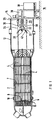
- a decommissioned, horizontally mounted steam generator 2 contains approximately 4000 U-shaped heating pipes 4 with a total length of approximately 40,000 m.
- the U-shaped heating tubes 4 are rolled and welded into a tube sheet 6 with the free ends of their legs and are additionally held by spacer grids 7.
- the heating tubes 4 are just above the tube sheet 6 along one dash-dot line illustrated separation surface 8 with a separated by a mounting opening 10 insertable device.
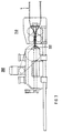
- a device 20 introduced according to the invention is on a mounting plate 14 of a mobile L-shaped frame 16 mounted.
- the mounting plate 14 also serves Shielding the open steam generator 2.
- the pulling device 22 comprises a hydraulically lockable Driving wedge 28, which is a heating tube 4 at the apex engages behind its arch 42 and a non-positive connection between the pulling device 22 and the heating pipe 4 manufactures.
- the pulling device 22 pulls the heating tube 4 through a spaced pair of rollers 30 that the radius of the arc 42 is reduced and insertion of the tube 4 in the pressing device 26 enables.
- the heating tube 4 is released after unlocking the driving wedge 28 pressed flat piece by piece and through the mounting plate 14 guided in the flat pressed state over the container 38 and separated by a cutter 36 so that it is in the container 38 falls.
- guide plates 32 In order to tilt the heating tube 4 when Prevent insertion into the rolling device 24 are on the rolling device 24 arranged guide plates 32.
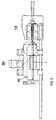
- a rolling device 240 which contains two pairs of rolls 242 and 244 arranged one behind the other.
- the distance between the rollers of a pair of rollers 242 or 244 is reduced in the drawing direction, so that kink-free preforming of the heating tube 4 is possible.
- the distance between the rollers of a pair of rollers 242 and 244 is at least so great that the driver wedge 224 hooked in at the apex of the sheet 42 can be passed through the rollers.
- the rolling rollers preferably have a rolling surface which is curved transversely to the running direction and which is adapted to the radius of the heating tube 4.
- the roller device 240 is at the free ends of two guide rods 248 fixed to the in this figure is not visible mounting plate 14 are arranged. Of the two Guide rods 248 is also only one in the figure visible.
- a pressing device is displaceable on the guide rods 248 260, which is a first pulling device 220 wearing.
- the pulling device 220 comprises a rack 222, the lockable driver wedge 224 at its free end wearing.
- the rack 222 is not over a in the figure visible pinion actuated by one on the pressing device arranged electric motor 226 is driven.
- the pressing device 260 comprises a dashed line Press beam 262, which uses two hydraulic cylinders 264 can be pressed against a fixed plate 266.
- a cutting device 360 is arranged, with the heating tube 4 pressed flat in the pressing device 260 can be sheared off.
- the device is in a working position shown, in which the not deformed heating tube 4 to to the first pair of roller rolls 242 of the rolling device 240 is.
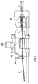
- FIG. 3 shows a working position in which the pull rod 222 has pulled the heating pipe 4 through the rolling device 240 up to the pressing device 260.
- the entire pressing device 260 is moved along the guide rods 248 relative to the rolling device 240 when the pull rod is locked, so that the heating tube 4 is pulled further through the rolling device 240 and preformed.
- the driver wedge 224 is then uncoupled and, according to FIG. 5, the pressing device 260 is moved back into its starting position to the rolling device 240, so that the preformed tube is located inside the pressing device 260. Then the press bar 262 is actuated hydraulically and the heating tube 4 is flattened.
- the pressing device 260 is then moved away again from the rolling device 240 and in this way pulls the heating pipe 4 further through the rolling device 240 in accordance with the travel path of the pressing device 260.
- the press bar 262 is retracted so that the heating tube 4 is released and the entire pressing device 260 is moved back to the starting position on the roller device 240 as shown in FIG. 7 , so that a preformed, but not yet pressed part of the heating tube 4 is inside the pressing device 260 located.
- On the end of the pressing device 260 facing away from the rolling device projects the flattened part of the heating tube 4, which can then be sheared off in the retracted position by means of the cutting device 360.
- FIGS. 8 and 9 show the reduction in volume of the heating tube 4 associated with the flat pressing.
- a round heating tube 4 with an outer diameter d ⁇ 22 mm is squeezed into a flat heating tube 4 with an approximately rectangular cross section with a height h ⁇ 3 mm and a width b ⁇ 35 mm.
- a volume reduction to a fifth can be achieved. This enables cost-effective transportation to the nuclear repository and economical storage.
- FIG. 10 illustrates that a cubic container 38 of edge length a ⁇ 1000 mm can hold almost 9000 on flat-pressed heating pipes cut into sections 4i of 1 m length, so that the entire tube bundle of a radioactively contaminated steam generator with four to five containers 38, which each have a volume of only 1 m 3 , can be disposed of.
Landscapes
- Engineering & Computer Science (AREA)
- Physics & Mathematics (AREA)
- High Energy & Nuclear Physics (AREA)
- Mechanical Engineering (AREA)
- General Engineering & Computer Science (AREA)
- Thermal Sciences (AREA)
- Processing Of Solid Wastes (AREA)
- Automatic Assembly (AREA)
Abstract
Claims (12)
- Procédé pour la mise au rebut d'un générateur (2) de vapeur contaminé par radioactivité, qui contient une pluralité de tubes (4) de chauffage coudés en U et débouchant dans une plaque (6) tubulaire, comprenant les étapes suivantes :a) détachement des tubes (4) de chauffage au-dessus de la plaque (6) tubulaire du générateur (2) de vapeur,b) réalisation d'une ouverture dans l'enveloppe du générateur (2) de vapeur, par détachement et dépose d'une partie supérieure de son dôme (12),c) prise en charge d'un tube (4) de chauffage par le coude du tube,d) traction du tube (4) de chauffage par l'ouverture au moyen d'un dispositif (22 ; 220) de traction.
- Procédé suivant la revendication 1, suivant lequeld1) la traction du tube (4) de chauffage par le dispositif (22 ; 220) de traction s'effectue dans un dispositif (24; 240) de laminage pour préformer le tube (4) de chauffage et diminuer le rayon de son coude, ete) le tube (4) de chauffage préformé est introduit dans un dispositif (26 ; 260) de compression pour le comprimer à plat.
- Procédé suivant la revendication 2, suivant lequel le dispositif (22 ; 220) de traction, le dispositif (24 ; 240) de laminage et le dispositif (26 ; 260) de compression sont disposés à l'intérieur du dôme (12).
- Procédé suivant la revendication 2 ou 3, suivant lequel le tube (4) de chauffage est tiré pas à pas hors du générateur (2) de vapeur et comprimé portion par portion.
- Procédé suivant l'une des revendications 2 à 4, suivant lequel le dispositif (220) de traction est disposé sur le dispositif (260) de compression et, au cours d'une première étape, tire le tube (4) de chauffage dans le dispositif (240) de laminage tandis que le dispositif (260) de compression est immobile, et suivant lequel, au cours d'une deuxième étape, le dispositif (260) de compression est déplacé par rapport au dispositif (240) de laminage et tire à nouveau le tube (4) de chauffage dans le dispositif (240) de laminage.
- Procédé suivant la revendication 5, suivant lequel le tube (4) de chauffage préformé est introduit dans le dispositif (260) de compression par un déplacement du dispositif (260) de compression en direction du dispositif (240) de laminage, et est comprimé par fermeture du dispositif (260) de compression.
- Procédé suivant la revendication 6, suivant lequel le dispositif (260) de compression fermé avec le tube (4) de chauffage comprimé, est éloigné du dispositif (240) de laminage et tire alors le tube (4) de chauffage d'une distance prescrite dans le dispositif (240) de laminage, puis est ouvert et, étant ouvert et le tube (4) de chauffage étant immobile, est déplacé à nouveau vers le dispositif (240) de laminage, puis est fermé et à nouveau éloigné, de sorte que le tube (4) de chauffage est tiré pas à pas hors du générateur de vapeur et comprimé portion par portion.
- Procédé suivant l'une des revendications 2 à 7, suivant lequel le tube (4) de chauffage comprimé à plat est fractionné en tronçons (4i) de longueur prescrite.
- Procédé suivant la revendication 8 conjointement avec la revendication 7, suivant lequel la partie comprimée à plat du tube (4) de chauffage est sectionnée après le retour en arrière du dispositif (260) de compression.
- Dispositif pour la mise en oeuvre du procédé suivant la revendication 1, comportanta) un dispositif de détachement pour détacher un tube (4) de chauffage au-dessus de la plaque (6) tubulaire du générateur (2) de vapeur, qui contient une pluralité de tubes (4) de chauffage en U qui débouchent dans la plaque (6) tubulaire,b) un dispositif (28, 244) de prise en charge pour prendre en charge le tube (4) de chauffage par le coude du tube,c) un dispositif (22 ; 220) de traction pour tirer le tube (4) de chauffage dans une ouverture de l'enveloppe du générateur (2) de vapeur, et un dispositif (24 ; 240) de laminage associé au dispositif (22 ; 220) de traction pour préformer le tube et diminuer le rayon de son coude,d) ainsi qu'un dispositif (26 ; 260) de compression pour comprimer à plat le tube (4) de chauffage préformé.
- Dispositif suivant la revendication 10, comportant un dispositif (260) de compression, qui peut être déplacé par rapport au dispositif (240) de laminage et sur lequel est monté le dispositif (220) de traction.
- Dispositif suivant la revendication 11, comportant un dispositif (360) de coupe disposé du côté du dispositif (260) de compression, qui est opposé au dispositif (240) de laminage, pour couper le tube (4) de chauffage.
Applications Claiming Priority (3)
| Application Number | Priority Date | Filing Date | Title |
|---|---|---|---|
| DE19541501A DE19541501A1 (de) | 1995-11-07 | 1995-11-07 | Verfahren und Vorrichtung zum Entsorgen eines nuklearen Dampferzeugers |
| DE19541501 | 1995-11-07 | ||
| PCT/EP1996/004694 WO1997017168A1 (fr) | 1995-11-07 | 1996-10-29 | Procede et dispositif pour la mise au rebut d'un generateur de vapeur contamine par radioactivite |
Publications (2)
| Publication Number | Publication Date |
|---|---|
| EP0859687A1 EP0859687A1 (fr) | 1998-08-26 |
| EP0859687B1 true EP0859687B1 (fr) | 1999-09-29 |
Family
ID=7776846
Family Applications (1)
| Application Number | Title | Priority Date | Filing Date |
|---|---|---|---|
| EP96937280A Expired - Lifetime EP0859687B1 (fr) | 1995-11-07 | 1996-10-29 | Procede et dispositif pour la mise au rebut d'un generateur de vapeur contamine par radioactivite |
Country Status (6)
| Country | Link |
|---|---|
| US (1) | US6041484A (fr) |
| EP (1) | EP0859687B1 (fr) |
| JP (1) | JP3732521B2 (fr) |
| DE (2) | DE19541501A1 (fr) |
| ES (1) | ES2138379T3 (fr) |
| WO (1) | WO1997017168A1 (fr) |
Cited By (1)
| Publication number | Priority date | Publication date | Assignee | Title |
|---|---|---|---|---|
| DE102017118075A1 (de) | 2017-08-09 | 2019-02-14 | Nukem Technologies Engineering Services Gmbh | Verfahren zum Rückbau eines Dampferzeugers |
Families Citing this family (11)
| Publication number | Priority date | Publication date | Assignee | Title |
|---|---|---|---|---|
| JP2005337778A (ja) * | 2004-05-25 | 2005-12-08 | Chubu Electric Power Co Inc | 給水加熱器伝熱管廃材の除染処理方法及びこの方法の実施に使用する半割切断機 |
| JP4509732B2 (ja) * | 2004-10-18 | 2010-07-21 | 株式会社アトックス | 小口径配管の半割方法及び装置 |
| JP4549269B2 (ja) * | 2005-09-20 | 2010-09-22 | 株式会社 エイブル | 管の再資源化方法 |
| JP5646972B2 (ja) * | 2010-12-01 | 2014-12-24 | 東京パワーテクノロジー株式会社 | 原子力発電所等で使用された管の引裂き装置及び引裂き方法 |
| JP5955173B2 (ja) * | 2012-09-14 | 2016-07-20 | 三菱重工業株式会社 | 蒸気発生器解体方法 |
| JP5972126B2 (ja) * | 2012-09-14 | 2016-08-17 | 富士古河E&C株式会社 | スクラップ処理システム及びスクラップ処理方法 |
| FR3002363B1 (fr) * | 2013-02-21 | 2015-03-20 | Andra | Procede de decontamination de tubes de generateur de vapeur |
| KR101843689B1 (ko) * | 2017-07-05 | 2018-03-29 | 한전케이피에스 주식회사 | 전열관 처리 장치 및 방법 |
| JP2020076621A (ja) * | 2018-11-07 | 2020-05-21 | 三菱重工業株式会社 | 原子力プラントの機器処理方法 |
| JP7313306B2 (ja) * | 2020-03-26 | 2023-07-24 | 株式会社神戸製鋼所 | 熱交換器の解体方法 |
| KR102357318B1 (ko) * | 2020-10-07 | 2022-02-07 | 한국수력원자력 주식회사 | 원자력 발전소의 증기 발생기의 내부 전열관 절단 장치 |
Family Cites Families (13)
| Publication number | Priority date | Publication date | Assignee | Title |
|---|---|---|---|---|
| DE1461117A1 (de) * | 1963-12-19 | 1969-12-04 | Kuesters Eduard Maschf | Verfahren und Vorrichtung zur fortlaufenden Entwaesserung von Zellstoffbahnen durch den Pressdruck eines Walzenpaares |
| US4406856A (en) * | 1980-09-29 | 1983-09-27 | Westinghouse Electric Corp. | Removal of portions of tubes from steam generator of nuclear reactor |
| GB2113598B (en) * | 1981-12-15 | 1985-12-11 | Omega Software | Heat exchanger maintenance |
| US4507840A (en) * | 1983-04-19 | 1985-04-02 | General Electric Company | Method for compacting nuclear reactor components |
| ZA854834B (en) * | 1984-07-16 | 1986-02-26 | Westinghouse Electric Corp | Secondary-side tube gripper |
| DE3521355A1 (de) * | 1985-06-14 | 1986-12-18 | Brown Boveri Reaktor GmbH, 6800 Mannheim | Absturzsicherung fuer eine vorrichtung zum ausziehen eines rohres aus einem rohrboden eines waermetauschers |
| FR2596433B1 (fr) * | 1986-04-01 | 1989-04-28 | Gerland Stowe Woodward Ind Bv | Cylindre de presse destinee notamment a eliminer le liquide d'un materiau en feuille, tel que pate a papier, elabore en continu, et presse comportant un tel cylindre |
| FR2630465A1 (fr) * | 1988-04-20 | 1989-10-27 | Gerland Stowe Woodward Ind Bv | Cylindre de presse pour fabrication de pate a papier ou feuille de papier |
| US5138754A (en) * | 1988-12-27 | 1992-08-18 | Combustion Engineering, Inc. | Double gripper tube puller |
| FR2687005B1 (fr) * | 1992-02-03 | 1994-10-21 | Framatome Sa | Procede et installation de decontamination de la partie primaire d'un generateur de vapeur usage d'un reacteur nucleaire a eau ordinaire sous pression. |
| US5276965A (en) * | 1992-02-13 | 1994-01-11 | The Atlantic Group, Inc. | Method for dismantling potentially contaminated tubes from a tube bundle |
| DE4411621A1 (de) * | 1994-04-02 | 1995-10-05 | Voith Sulzer Papiermasch Gmbh | Preßmantel |
| US5623526A (en) * | 1995-07-21 | 1997-04-22 | Combustion Engineering, Inc. | Method and apparatus for repair of nuclear reactor shroud |
-
1995
- 1995-11-07 DE DE19541501A patent/DE19541501A1/de not_active Ceased
-
1996
- 1996-10-29 ES ES96937280T patent/ES2138379T3/es not_active Expired - Lifetime
- 1996-10-29 DE DE59603243T patent/DE59603243D1/de not_active Expired - Lifetime
- 1996-10-29 EP EP96937280A patent/EP0859687B1/fr not_active Expired - Lifetime
- 1996-10-29 WO PCT/EP1996/004694 patent/WO1997017168A1/fr not_active Ceased
- 1996-10-29 JP JP51780197A patent/JP3732521B2/ja not_active Expired - Fee Related
-
1998
- 1998-05-07 US US09/074,433 patent/US6041484A/en not_active Expired - Lifetime
Cited By (2)
| Publication number | Priority date | Publication date | Assignee | Title |
|---|---|---|---|---|
| DE102017118075A1 (de) | 2017-08-09 | 2019-02-14 | Nukem Technologies Engineering Services Gmbh | Verfahren zum Rückbau eines Dampferzeugers |
| DE102017118075B4 (de) | 2017-08-09 | 2021-09-30 | Nukem Technologies Engineering Services Gmbh | Verfahren zum Rückbau eines Dampferzeugers |
Also Published As
| Publication number | Publication date |
|---|---|
| WO1997017168A1 (fr) | 1997-05-15 |
| JP3732521B2 (ja) | 2006-01-05 |
| ES2138379T3 (es) | 2000-01-01 |
| US6041484A (en) | 2000-03-28 |
| DE19541501A1 (de) | 1997-05-15 |
| JPH11514588A (ja) | 1999-12-14 |
| EP0859687A1 (fr) | 1998-08-26 |
| DE59603243D1 (de) | 1999-11-04 |
Similar Documents
| Publication | Publication Date | Title |
|---|---|---|
| EP0859687B1 (fr) | Procede et dispositif pour la mise au rebut d'un generateur de vapeur contamine par radioactivite | |
| DE2161534C2 (de) | Verfahren zum Zerlegen eines bestrahlten Kernreaktor-Brennelementbündels und Vorrichtung zur Durchführung des Verfahrens | |
| EP4135916B1 (fr) | Système de soudage de plaques pour la production de plaques de béton armé et procédé utilisant celui-ci | |
| DE3416620C2 (de) | Unterwasser-Zerkleinerungsvorrichtung | |
| DE3505242C2 (fr) | ||
| DE3212140A1 (de) | Vorrichtung zum eindaemmen des austretens von spaltgas durch ein loch in einem kernbrennstoffstab | |
| EP0252375B1 (fr) | Méthode pour réparer un assemblage de combustible nucléaire et crayon de remplacement utilisé pour la mise en oeuvre | |
| DE2843531C2 (de) | Maschine zum Herstellen von gitterträgerartigen Bewehrungsgebilden für Stahlbeton | |
| DE3115501A1 (de) | Verfahren und vorrichtung zum richten von von kathodenblechen abgeloesten tragstangen in elektrolytischen raffinationsanlagen | |
| DE3506584A1 (de) | Einrichtung zum einsetzen von kernbrennstoff oder neutronenabsorberstoff enthaltenden staeben in einer vorgegebenen dichten packung in einen behaelter | |
| DE3701258A1 (de) | Verfahren zum kompaktieren verbrauchter kernbrennstoffstaebe aus einer halterung und vorrichtung zur durchfuehrung des verfahrens | |
| DE68906721T2 (de) | Verfahren zum Verdichten des Skeletts einer nuklearen brennbaren Zusammenstellung. | |
| DE3341714C2 (fr) | ||
| DE3316134C2 (de) | Verfahren und Vorrichtung zum Herstellen von Schutzrohren mit flachem Querschnitt für Betonbewehrungsstäbe | |
| EP3453960B1 (fr) | Procédé de démantèlement d'un générateur de vapeur | |
| DE4243969C2 (de) | Vorrichtung zum Zusammenbauen eines Brennelements | |
| DE3530410C2 (fr) | ||
| AT507133B1 (de) | Vorrichtung zum entsorgen von restdraht | |
| DE19542339C1 (de) | Verfahren und Vorrichtung zum Öffnen von gefüllten Einwegfässern | |
| DE102005013984B3 (de) | Vorrichtung und Verfahren zum Konditionieren eines Brennelementskelettes eines Kernreaktors | |
| DE4240286A1 (de) | Kompaktpresse mit vollautomatischer Ballenverpackung | |
| DE3332581A1 (de) | Verfahren zum einschliessen der brennstoffkanaele von verbrauchten brennelementkaesten fuer brennelementbuendel in kernreaktoren | |
| DE2620419A1 (de) | Maschine zur herstellung von tiefwellenwaenden fuer kessel, insbesondere von transformatoren | |
| DE3529312A1 (de) | Verfahren zum enthuellen bzw. auseinandernehmen von bestrahlten kernbrennstoffelementen | |
| WO1994014550A1 (fr) | Procede pour le chargement d'une billette et presse a extruder les metaux |
Legal Events
| Date | Code | Title | Description |
|---|---|---|---|
| PUAI | Public reference made under article 153(3) epc to a published international application that has entered the european phase |
Free format text: ORIGINAL CODE: 0009012 |
|
| 17P | Request for examination filed |
Effective date: 19980420 |
|
| AK | Designated contracting states |
Kind code of ref document: A1 Designated state(s): BE CH DE ES LI |
|
| 17Q | First examination report despatched |
Effective date: 19980929 |
|
| GRAG | Despatch of communication of intention to grant |
Free format text: ORIGINAL CODE: EPIDOS AGRA |
|
| GRAG | Despatch of communication of intention to grant |
Free format text: ORIGINAL CODE: EPIDOS AGRA |
|
| GRAH | Despatch of communication of intention to grant a patent |
Free format text: ORIGINAL CODE: EPIDOS IGRA |
|
| GRAH | Despatch of communication of intention to grant a patent |
Free format text: ORIGINAL CODE: EPIDOS IGRA |
|
| GRAA | (expected) grant |
Free format text: ORIGINAL CODE: 0009210 |
|
| AK | Designated contracting states |
Kind code of ref document: B1 Designated state(s): BE CH DE ES LI |
|
| REG | Reference to a national code |
Ref country code: CH Ref legal event code: NV Representative=s name: SIEMENS SCHWEIZ AG Ref country code: CH Ref legal event code: EP |
|
| REF | Corresponds to: |
Ref document number: 59603243 Country of ref document: DE Date of ref document: 19991104 |
|
| REG | Reference to a national code |
Ref country code: ES Ref legal event code: FG2A Ref document number: 2138379 Country of ref document: ES Kind code of ref document: T3 |
|
| PLBE | No opposition filed within time limit |
Free format text: ORIGINAL CODE: 0009261 |
|
| STAA | Information on the status of an ep patent application or granted ep patent |
Free format text: STATUS: NO OPPOSITION FILED WITHIN TIME LIMIT |
|
| 26N | No opposition filed | ||
| REG | Reference to a national code |
Ref country code: CH Ref legal event code: PUE Owner name: SIEMENS AKTIENGESELLSCHAFT TRANSFER- FRAMATOME ANP |
|
| REG | Reference to a national code |
Ref country code: CH Ref legal event code: PFA Owner name: AREVA NP GMBH Free format text: FRAMATOME ANP GMBH#FREYESLEBENSTRASSE 1#91058 ERLANGEN (DE) -TRANSFER TO- AREVA NP GMBH#FREYESLEBENSTRASSE 1#91058 ERLANGEN (DE) |
|
| REG | Reference to a national code |
Ref country code: CH Ref legal event code: PCOW Free format text: AREVA NP GMBH;PAUL-GOSSEN-STRASSE 100;91052 ERLANGEN (DE) |
|
| PGFP | Annual fee paid to national office [announced via postgrant information from national office to epo] |
Ref country code: ES Payment date: 20111024 Year of fee payment: 16 Ref country code: BE Payment date: 20111024 Year of fee payment: 16 Ref country code: CH Payment date: 20111025 Year of fee payment: 16 |
|
| PGFP | Annual fee paid to national office [announced via postgrant information from national office to epo] |
Ref country code: DE Payment date: 20111216 Year of fee payment: 16 |
|
| BERE | Be: lapsed |
Owner name: *AREVA NP G.M.B.H. Effective date: 20121031 |
|
| REG | Reference to a national code |
Ref country code: CH Ref legal event code: PL |
|
| PG25 | Lapsed in a contracting state [announced via postgrant information from national office to epo] |
Ref country code: DE Free format text: LAPSE BECAUSE OF NON-PAYMENT OF DUE FEES Effective date: 20130501 Ref country code: CH Free format text: LAPSE BECAUSE OF NON-PAYMENT OF DUE FEES Effective date: 20121031 Ref country code: LI Free format text: LAPSE BECAUSE OF NON-PAYMENT OF DUE FEES Effective date: 20121031 Ref country code: BE Free format text: LAPSE BECAUSE OF NON-PAYMENT OF DUE FEES Effective date: 20121031 |
|
| REG | Reference to a national code |
Ref country code: DE Ref legal event code: R119 Ref document number: 59603243 Country of ref document: DE Effective date: 20130501 |
|
| REG | Reference to a national code |
Ref country code: ES Ref legal event code: FD2A Effective date: 20140116 |
|
| PG25 | Lapsed in a contracting state [announced via postgrant information from national office to epo] |
Ref country code: ES Free format text: LAPSE BECAUSE OF NON-PAYMENT OF DUE FEES Effective date: 20121030 |