EP0860070B1 - Dispositif et procede relatif au controle de flux de paquets - Google Patents
Dispositif et procede relatif au controle de flux de paquets Download PDFInfo
- Publication number
- EP0860070B1 EP0860070B1 EP96938576A EP96938576A EP0860070B1 EP 0860070 B1 EP0860070 B1 EP 0860070B1 EP 96938576 A EP96938576 A EP 96938576A EP 96938576 A EP96938576 A EP 96938576A EP 0860070 B1 EP0860070 B1 EP 0860070B1
- Authority
- EP
- European Patent Office
- Prior art keywords
- signals
- arrangement
- buffering
- traffic
- packets
- Prior art date
- Legal status (The legal status is an assumption and is not a legal conclusion. Google has not performed a legal analysis and makes no representation as to the accuracy of the status listed.)
- Expired - Lifetime
Links
Images

Classifications
-
- H—ELECTRICITY
- H04—ELECTRIC COMMUNICATION TECHNIQUE
- H04L—TRANSMISSION OF DIGITAL INFORMATION, e.g. TELEGRAPHIC COMMUNICATION
- H04L49/00—Packet switching elements
- H04L49/25—Routing or path finding in a switch fabric
- H04L49/256—Routing or path finding in ATM switching fabrics
-
- H—ELECTRICITY
- H04—ELECTRIC COMMUNICATION TECHNIQUE
- H04L—TRANSMISSION OF DIGITAL INFORMATION, e.g. TELEGRAPHIC COMMUNICATION
- H04L49/00—Packet switching elements
- H04L49/25—Routing or path finding in a switch fabric
-
- H—ELECTRICITY
- H04—ELECTRIC COMMUNICATION TECHNIQUE
- H04L—TRANSMISSION OF DIGITAL INFORMATION, e.g. TELEGRAPHIC COMMUNICATION
- H04L12/00—Data switching networks
- H04L12/54—Store-and-forward switching systems
- H04L12/56—Packet switching systems
- H04L12/5601—Transfer mode dependent, e.g. ATM
- H04L12/5602—Bandwidth control in ATM Networks, e.g. leaky bucket
-
- H—ELECTRICITY
- H04—ELECTRIC COMMUNICATION TECHNIQUE
- H04L—TRANSMISSION OF DIGITAL INFORMATION, e.g. TELEGRAPHIC COMMUNICATION
- H04L49/00—Packet switching elements
- H04L49/20—Support for services
- H04L49/205—Quality of Service based
-
- H—ELECTRICITY
- H04—ELECTRIC COMMUNICATION TECHNIQUE
- H04L—TRANSMISSION OF DIGITAL INFORMATION, e.g. TELEGRAPHIC COMMUNICATION
- H04L49/00—Packet switching elements
- H04L49/30—Peripheral units, e.g. input or output ports
- H04L49/3081—ATM peripheral units, e.g. policing, insertion or extraction
-
- H—ELECTRICITY
- H04—ELECTRIC COMMUNICATION TECHNIQUE
- H04L—TRANSMISSION OF DIGITAL INFORMATION, e.g. TELEGRAPHIC COMMUNICATION
- H04L12/00—Data switching networks
- H04L12/54—Store-and-forward switching systems
- H04L12/56—Packet switching systems
- H04L12/5601—Transfer mode dependent, e.g. ATM
- H04L2012/5629—Admission control
- H04L2012/5631—Resource management and allocation
- H04L2012/5632—Bandwidth allocation
-
- H—ELECTRICITY
- H04—ELECTRIC COMMUNICATION TECHNIQUE
- H04L—TRANSMISSION OF DIGITAL INFORMATION, e.g. TELEGRAPHIC COMMUNICATION
- H04L12/00—Data switching networks
- H04L12/54—Store-and-forward switching systems
- H04L12/56—Packet switching systems
- H04L12/5601—Transfer mode dependent, e.g. ATM
- H04L2012/5638—Services, e.g. multimedia, GOS, QOS
- H04L2012/5646—Cell characteristics, e.g. loss, delay, jitter, sequence integrity
- H04L2012/5651—Priority, marking, classes
-
- H—ELECTRICITY
- H04—ELECTRIC COMMUNICATION TECHNIQUE
- H04L—TRANSMISSION OF DIGITAL INFORMATION, e.g. TELEGRAPHIC COMMUNICATION
- H04L49/00—Packet switching elements
- H04L49/30—Peripheral units, e.g. input or output ports
-
- H—ELECTRICITY
- H04—ELECTRIC COMMUNICATION TECHNIQUE
- H04L—TRANSMISSION OF DIGITAL INFORMATION, e.g. TELEGRAPHIC COMMUNICATION
- H04L49/00—Packet switching elements
- H04L49/50—Overload detection or protection within a single switching element
Definitions
- the present invention relates to an arrangement for controlling the flow of signals comprising a number of information packets in a communications network.
- the invention also relates to a method of controlling the flow of signals in the form of information packets.
- the invention relates to controlling the flow of information incoming to concentrating arrangements and most particularly to switching arrangements in communications systems.
- Each packet comprises a header and a data field.
- the header is the preamble of the packet and contains information about destination address, sometimes also originating address and control bits whereas the data part comprises the information intended for the given address.
- a cell is a short packet having a predetermined number of bits, i.e. a packet of a fixed length.
- Switching arrangement which operate in so called synchronous transfer mode (STM) are known as well as other switching arrangements operating in asynchronous transfer mode (ATM). Some switching arrangements may also operate in both modes.
- the ATM switching technique is a so called fast packet switching technique. This switching technique is particularly applicable when different sources have different requirements as to bandwidth. Via ATM different or mixed traffic streams such as for example data, voice, video or images can be transmitted asynchronously which is clearly advantageous in modern communication systems wherein one or more kinds of information may need to be transmitted.
- ATM information is transported in the form of cells, i.e. packets of a fixed length. It is of great importance to the network how the packet switches operate.
- a number of cells may for instance arrive at a switch on a number of different input links at the same time and a number of them may have the same output link destination or there may be a discrepancy between the number of input links and the number of output links wherein the number of output links is considerably lower than the number of input links.
- This means that a number incoming cells may have to compete for an output link.
- the output link cannot handle more than one cell at a time meaning that the other cells have to be stored temporarily in a buffer. This puts high demands on the buffering capacity and in some cases the capacity may not be sufficient and the cells may even run the risk-of being completely lost. It may also be difficult to fulfil the requirements as to waiting time etc.
- HOL head of the line problem
- This is a problem that may occur when a number of data cells are stored in an input buffer which is a waiting position, i.e. the first cell in the buffer is waiting to be served. Then all data cells contained in that buffer have to wait, also those cells further down in the queue which are destined for other output links which for example at that moment might not be loaded at all. This means that neither the packet switch nor the output links are used to their full capacity but even very poorly.
- output buffers have been provided as well as intermediate buffers in a switch core etc.
- CBR constant bit rate
- VBR variable bit rate
- a third category relates to ABR signals wherein ABR means available bit rate.
- the demands as to variations in delay are low or even none at all for these signals. What is important is that no cells are lost.
- the signals are e.g. used for data communication.
- One controlling method based on cellrate measurements has been suggested. This means that switching arrangements in a network receiving ATM ABR signals may calculate a value on an adequate cellrate and feeding this information back to the sources of the signals.
- a source here means either a network terminating equipment or equipment within the network forming terminating equipment only as far as the flow control is concerned.
- the method is based on measuring and feeding back of cellrate parameters, it works poorly when the cellrate is close to saturation. This means that links, for example expensive links, e.g. are not used fully or to an acceptable degree.
- WO 92/19060 an ATM switching arrangement is disclosed.
- Cells are divided into low loss and low delay cells respectively and the switching arrangement comprises a cell buffer which is divided into one memory area for each of the two types of cells.
- the cells are given different priorities for reading in and reading out respectively.
- Such an arrangement could however not in a satisfactory way deal with ABR signals.
- US-A-5 153 877 relates to allocation of the resources in a packet network.
- the resources are subdivided into subresources which are to be allocated to communications divided into different classes depending on QoS such as packet lossrate and transmission delay. Also this document does not deal with resource allocation for ABR signals.
- EP-A1-0 678 997 discloses a switch in an ATM-network that separates the incoming traffic in two different types of traffic: ABR-signals and other signals. ABR-traffic is interrupted whenever other type of traffic is transmitted.
- EP-A2-0 596 624 discloses a method for dedicating bandwidth in an ATM-network, in which signals are separated based on bandwidth requirements.
- the network handels data that is only sent when bandwidth is available.
- ABR signals for instance are particularly difficult to handle since irrespective of being of one and the same QoS, they can be of different categories such as being guaranteed resources to different extents. There may thus be a variation between not being guaranteed any resources at all up to being guaranteed resources to a considerable or a significant extent.
- What is needed is therefore an arrangement through which links in a communication network can be used in an optimal way.
- An arrangement is particularly needed through which the output links of a concentrating or switching arrangement can be used to a desired degree, for example be used maximally or at least more efficiently than in hitherto existing systems.
- An arrangement is also needed through which the flow control of ATM signals can be done in an easy and reliable way while fulfilling different requirements of different signals.
- a method is needed through which the flow of signals in the form of information packets can be controlled in such a way that links, particularly output links from concentrating, e.g. switching arrangements or expensive links, can be used optimally.
- a method is also needed through which ATM signals of different QoS or of different types within one and the same QoS can be switched through the network in a way which is adequate for the respective signals while still meeting their respective requirements.
- a flow controlling arrangement is further also needed through which the flow control can be implemented in a simple and non-expensive way without considerably affecting the concentrating/switching arrangements or maybe even without affecting them at all.
- an arrangement which comprises means for separating traffic signals at least into those having a higher proportion of guaranteed resources and those having a lower proportion of guaranteed resources.
- the arrangement furthermore comprises means for separately handling signals of the first and second kind respectively.
- the traffic signals of the first mentioned kind have a higher proportion of guaranteed bandwidth than the signals of the second kind.
- the first mentioned signals are given a lower priority than the signals having a lower proportion of guaranteed resources or particularly bandwidth.
- the traffic signals particularly relate to signals having a lower proportion of cells that are guaranteed resources e.g. in the form of bandwidth which then are given a higher priority.
- the arrangement comprises a buffering unit in which packets can be arranged in at least one queue.
- the buffering unit particularly comprises a first buffering area wherein low priority packets can be stored in at least one queue.
- cells or packets of the same QoS e.g. ABR cells which have a high proportion of guaranteed bandwidth are stored in the queue in the first buffering area whereas the ABR cells having a lower proportion of guaranteed bandwidth are stored in the second area of the buffering unit.
- the packets or cells may be arranged in the buffering unit both depending on QoS and on proportion of guaranteed bandwidth.
- monitoring means are provided for measuring the cellrate of signals not being guaranteed a significant proportion of resources or bandwidth whereas monitoring means also are provided for monitoring the queue status in the buffer area of signals having a low priority which thus provides first and second flow control signals which are provided to the sources for controlling purposes.
- ABR Explicit Rate parameters relate to an estimation by the concentrating arrangement relating to what sending cellrate can be accepted and they are provided to the sources via the resource management cells.
- VSES virtual source end system
- cell credit control relates to storing in the buffering unit irrespectively of whether particular cell credit parameters are used or cellrate parameters of the other method.
- the arrangement is implemented at the input unit of a switch core.
- the switching arrangement has the features of the arrangement as described in the simultaneously filed patent application by the same applicant which was referred to above.
- the invention is applicable to arrangements in general wherein a concentration occurs e.g. requiring any kind of buffering arrangement.
- the arrangement may comprise a virtual flow controlling element of the network, element in this case relating to a segment as defined in relation to ATM ABR signals.
- the arrangement in a particular embodiment relates to signals having different proportions of guaranteed resources or bandwidth irrespectively of whether they belong to different QoS or whether there are different types of signals of the same QoS, as e.g. ABR signals which as such can be of different types.
- signals may be handled in more than two different ways, for example there may be separate buffers for one or two or even more of the types of signals i.e. depending on their proportion of guaranteed resources particularly of the same QoS.
- the signals more or less sensitive to being stored temporarily are stored in one buffer area whereas those signals being well capable of being stored to some extent are stored in another area of the buffering means, whereas those signals who are not guaranteed any bandwidth at all or at least substantially no bandwidth, are controlled via an ordinary cellrate flow controlling method.
- they may be stored in separate buffers.
- the invention also provides a switching arrangement for switching information packets incoming to at least one inlet unit on a number of input links, through a switch core on to a number of output links which comprises means for separation of incoming traffic signals into at least first and second traffic signals wherein the first traffic signals comprises a higher proportion of packets guaranteed resources than the second traffic signals.
- Flow control of at least one of said first or second traffic signals is handled separately from the other traffic signals.
- the first and second traffic streams of signals respectively are not only handled separately but also differently.
- the first traffic signals are handled using a cell credit flow control method, i.e. the cells are temporarily stored in a buffering unit separately from said second signals until they can be switched whereas the second traffic stream is handled using a cellrate flow control method.
- the invention therefore also provides a method of controlling the flow of signals in the form of cells incoming on a number of input links to a concentrating arrangement such as e.g. a switching arrangement or a multiplexing arrangement etc. according to which these signals are at least separated into those signals having a proportion of guaranteed bandwidth which exceeds a given threshold value from the rest of the signals, and handling the flow of these signals separately from said other signals.
- a concentrating arrangement such as e.g. a switching arrangement or a multiplexing arrangement etc.
- those signals having a proportion of guaranteed bandwidth or resources being smaller than the threshold value are given a higher priority.
- Cellrate measurements may then be undertaken relating to these signals whereas information on buffering status of the non-prioritized cells is fed back to the sources for flow controlling purposes, i.e. to instruct the sources on how to adjust the sending frequency etc.
- Sources may here mean either a real source and system or a virtual source end system.
- Another advantage is that this can be achieved without requiring advanced and costly modifications of concentrating arrangements in general or switching arrangements in particular.
- a part of incoming traffic signals comprises signals which are guaranteed resources or bandwidth to a proportion exceed a given threshold value, these are separated from the other signals.
- These traffic signals which in the following are denoted first traffic signals, are given resources in the form of separate queue handling. Feedback signals concerning buffering unit sizes and control flow delays etc. are used in order to enable saturation of the links, i.e. filling of the links without causing congestion since the flow through is guaranteed to the first traffic signals.
- flow controlling arrangements can e.g. be implemented in network nodes such as switching arrangements multiplexers etc. but flow controlling arrangements can also be implemented elsewhere in the network. Below an embodiment relating to the implementation of a flow controlling arrangement in a switching arrangement or in association with a switching arrangement will be described under reference to Fig. 2.
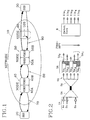
- Fig. 1 illustrates a system comprising a network 10, a source end system SES 20 and a destination end system DES 30.
- the network comprises a number of nodes 40,50,60. Two of the nodes 40,50 each comprise a virtual destination end system VDES 40A;50A and a virtual source end system VSES 40B;50B.
- the third node 60 is an ordinary node such as a switch or a multiplexer.
- the invention can be implemented in a concentrating arrangement or similar (switching arrangement, multiplexer, etc.) needing a buffer or similar, c.f. node 60 which will be more thoroughly explained under reference to figs 2 and 3 or it can be implemented as control purpose elements; c.f. nodes 40,50 in Fig. 1.
- VDES 40A of node 40 control signals are fed back via an ABR flow control feedback loop 70.
- signals relating to measurement results, cellrate measurements and/or feedback measurements on the first and second signals respectively are fed back to the real source, a source end system SES 20, they must be expressed in terms of cellrate or ABR Explicit Cellrate as will be further illustrated under reference to Fig. 3. Only if signals are fed back to a virtual source end system (within the network) they may comprise credit based information according to a protocol defined by the networks.
- Credit based flow control here means that the calculation of feedback signals is done taking into account the buffering capacity that is required in order to be able to handle the flow according to the ABR controlling algorithm and line delays even if no positive feedback has taken place.
- Cellrate flow control here comprises a calculation of the feedback signal in relation to the available bandwidth. In both cases a value on acceptable rate is fed back (e.g. in agreement with the ATM ABR specifications).
- the internal flow control loops 80,90 are specified for the particular network.
- the loop parameters may e.g. directly give the available buffer space. This is however non-transparent in the network interface.
- the ordinary node 60 which as already referred to above e.g. can be switch or a multiplexer does not have to close or complete the control loop itself.
- the control parameters describing the results of the measurements are included into resource management cells RM.
- Such RM cells are generally included in every connection in a regular manner.
- Such resource management cells RM are generated by the source, SES or VSES.
- the destination systems, DES or VDES, always return the RM cells via feedback loops to the source (SES or VSES).
- An ordinary node 60 may alternatively close the loop by including, as indicated by 100, RM cells in the feedback loop 90. This is e.g. a way of accelerating the feeding back of signals and thus to speed up the procedure.
- Fig. 2 an implementation relating to a switching arrangement is illustrated.
- Signals from a number of sources here merely denoted S, which is intended to mean a number of different sources are coming in on a number of input links 1a, 2a, 3a (1A) to a multiplexing device 2A in which they are concentrated or multiplexed.
- the traffic streams or the traffic signals are arranged at least depending on QoS. It should however be clear that it is not necessary for the functioning of the present invention that a separation depending on QoS is done but this merely relates to a particular embodiment. What is important for the present invention is that a separation is done for signals having different proportions of guaranteed resources, either into two groups or into more groups.
- a buffering unit 5A is provided which comprises two different buffering areas, the first buffering area 5A 1 , for example for ABR signals having a significant proportion of guaranteed bandwidth which then e.g. are stored in queues 5a 4 , 5a 5 and the second buffering area 5A 2 for signals not having a high proportion of guaranted bandwidth or more generally second signals as defined above.
- the highest priority is e.g. given to CBR signals (if such are present), constant bit rate signals which are very sensitive to buffering which thus for example may be stored in queue 5a 1 .
- the second queue 5a 2 is for example used for VBR signals i.e. variable bit rate signals which are somewhat less sensitive to buffering. Of course this is just an example, in many cases there may not even be any VBR (or CBR) signals, these are merely included for exemplifying reasons.
- the third queue 5a 3 is used for signals not being guaranteed bandwidth to any significant proportion, such as ABR signals or more generally second signals as defined above.
- 5a 4 , 5a 5 denote queues of the first area 5A 1 intended for ABR signals or other signals which are guaranteed bandwidth and which can be stored but for which no cells or substantially no cells should be lost.
- Measuring means are further provided, (not further illustrated in this figure since their functioning should be known per se) for measuring the cellrate of the second signals in a manner known per se and for measuring the queue status of the second signals or low priority signals which also can be done in different ways in some known manner. The results of these measurements are then fed back to the sources so that they can control their sending of cells correspondingly. It should however be noted that the data resulting from the measurements, i.e.
- the results have to be converted into ABR Explicit Rate parameters before feeding back if fed back to a real source end system SES as discussed above under reference to Fig. 1.
- the signals are then switched through the switch core 8 in a manner known per se and output on the destination output links 11a 1 -11a 4 also in any manner known per se.
- the arrangements as described above are intended to use the available bandwidth to the greatest possible extent and at the same time use the buffering areas to a certain extent for that part of the traffic streams which can be queued in order to get hold of the remaining bandwidth which otherwise could not be fully exploited. This means that output links of the switching arrangement can be more efficiently used, leaving in practice none or very little capacity unused.
- An arrangement according to the present invention gets more efficient the higher the proportion of traffic having a guaranteed bandwidth.
- the composition of communications get more homogenous so that the level of acceptance as to storing in queues is more similar within the respective streams.
- a queue of an adequate size can be formed for using the last available bandwidth of e.g. an expensive output link.
- the flow controlling arrangement of the invention combines cellrate flow controlling with cell credit flow controlling.
- Fig. 3 illustrates in a more detailed manner the transmission of data and the feedback flow control signals.
- Fig. 3 in principle corresponds to Fig. 2.
- a switch core 8' is illustrated (like the switch core 8 of Fig.2 ) it should be clear that it does not have to be a switch core. It can be any kind of signal concentrating arrangement which motivates the use of some buffering arrangement comprising separation e.g. into different QoS.
- a concentration of signals on a number of input links 1A' is done in a multiplexing arrangement 2A'.
- the streams of signals are in the demultiplexing arrangement 3A' separated into different groups depending on QoS and stored in queues in the buffering arrangement 5A' e.g.as described under reference to Fig. 2.
- Through monitoring arrangement 12' cellrate measurements and queue status measurements are undertaken. Since the signal source in this case is a source end system SES 20' the queue status results are converted in conversion arrangement 13' into ABR Explicit Rate parameters and used in the modification arrangement for modification of resource management cells RM. These are by the destination terminal (not illustrated in the figure) via a feedback loop sent to the originating terminal, i.e. SES 20'.
- the switching arrangement can take the form of a switching arrangement as described in the above cited patent application which is incorporated herein by reference.
- the switch core 8;8' then comprises a number (two or more) of inlet units and a number outlet units wherein to each inlet unit a main buffer unit 5A,5A' is provided which in this case also comprises the functionality as described above.
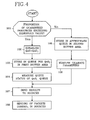
- Fig. 4 is schematical flow diagram.
- the proportion of guaranteed resources is examined 101. If it exceeds a given threshold value, the QoS, is established 102 and the cell is stored in the appropriate queue in the first buffer area 103. Then the queue status of the queue QoS i is measured 104 and the result is fed back to the sending sources 107 in which the sending of cells is controlled accordingly 108 e.g. the sending rate can be increased, decreased or kept at the same level. As discussed in the foregoing, a conversion has to be done if the result is fed back to a real end source.
- the arranging or combination of flow controlling arrangements in a network either as separate or implemented at the input part or inlet unit of a switching arrangement.
- the invention also applies likewise to any QoS or any service classes as ABR etc., irrespectively of whether the cells are within the same service class, such as ABR, or in different classes as far as the proportion of guaranteed resources is concerned. It is also possible to divide the cells into more than those two groups corresponding to those having a significant proportion guaranteed bandwidth and those who do not, such as for example into more groups for which different threshold values are given etc.
Landscapes
- Engineering & Computer Science (AREA)
- Computer Networks & Wireless Communication (AREA)
- Signal Processing (AREA)
- Quality & Reliability (AREA)
- Data Exchanges In Wide-Area Networks (AREA)
Abstract
Claims (28)
- Montage pour commander le flux de signaux (IA, IA') comprenant un certain nombre de paquets d'informations dans un réseau (10) de communications, ledit montage comportant un moyen destiné à séparer les signaux (3A, 3A') en au moins des premiers signaux de trafic (5A1) et des seconds signaux de trafic (5A2),
caractérisé en ce que
les premiers signaux de trafic sont des signaux ayant une proportion plus élevée de ressources garanties que les seconds signaux de trafic, et en ce que des moyens (5A', 5A') sont en outre prévus pour traiter séparément les premiers et seconds signaux de trafic, et en ce qu'il est donné aux premiers signaux de trafic une priorité inférieure à celle des seconds signaux de trafic. - Montage selon la revendication 1,
caractérisé en ce que
les premiers signaux de trafic sont des signaux ayant une proportion importante d'une largeur de bande garantie. - Montage selon la revendication 1 ou 2,
caractérisé en ce que
un courant de trafic comprenant des signaux de trafic ayant une proportion inférieure de paquets qui sont des ressources garanties, par exemple sous la forme d'une largeur de bande, a une priorité supérieure. - Montage selon la revendication 3,
caractérisé en ce que
il comporte en outre un montage tampon (5A ; 5A') dans lequel des paquets peuvent être agencés en au moins une file d'attente. - Montage selon la revendication 4,
caractérisé en ce que
le montage tampon (5A ; 5A') comporte au moins une première zone tampon (5A2) dans laquelle des paquets de basse priorité peuvent être stockés. - Montage selon la revendication 5,
caractérisé en ce que
des paquets ayant pour origine des terminaux présentant différents QoS sont agencés dans un certain nombre de files d'attente différentes, dépendant au moins du QoS, dans le montage tampon (5A ; 5A'). - Montage selon la revendication 6,
caractérisé en ce que
un moyen d'agencement de file d'attente agence les paquets des courants de trafic dans le montage tampon (5A ; 5A') suivant au moins le QoS et la proportion de largeur de bande garantie, et dans lequel des paquets peuvent être agencés dans des zones tampons différentes même s'ils ont le même QoS. - Montage selon l'une quelconque des revendications 4 à 7,
caractérisé en ce que
des moyens de contrôle (12') sont prévus pour mesurer le débit de cellules de signaux ayant une haute priorité et des moyens sont prévus pour contrôler l'état de file d'attente dans des zones tampons pour des signaux ayant une priorité inférieure, procurant ainsi des premier et second signaux de commande de flux devant être utilisés à des fins de commande de flux. - Montage selon l'une quelconque des revendications précédentes,
caractérisé en ce que
une commande de flux de crédit de cellules est combinée avec une commande de flux de débit de cellules pour maximiser l'utilisation de la capacité d'une liaison sans provoquer une congestion de la liaison. - Montage selon l'une quelconque des revendications 4 à 9,
caractérisé en ce que
le montage tampon (5A; 5A') et les moyens d'agencement de file d'attente sont matérialisés à l'unité d'entrée et au moyen tampon d'entrée correspondant d'un coeur de commutation (8 ; 8'). - Montage selon l'une quelconque des revendications précédentes,
caractérisé en ce que
les signaux comprennent des cellules ATM, le montage fonctionnant ainsi en mode ATM. - Montage selon la revendication 11,
caractérisé en ce que
au moins certains des signaux sont des signaux ABR. - Montage selon l'une quelconque des revendications 1 à 12,
caractérisé en ce que
il comporte un élément de commande de flux virtuel agencé de façon interne dans un réseau comprenant un système d'extrémité de source virtuelle (VSES) et un système d'extrémité de destination virtuelle (VDES). - Montage de commutation comprenant un montage selon l'une quelconque des revendications 1 à 13, ledit montage de commutation étant prévu pour commuter des paquets d'informations arrivant à au moins une unité d'entrée sur un certain nombre de liaisons d'entrée en passant par un coeur de commutation (8 ; 8'), sur un certain nombre de liaisons de sortie (11a1,...11a4 ; 11A', 1A ; 1A').
- Montage selon la revendication 14,
caractérisé en ce que
des courants de trafic comprenant des signaux ayant une proportion de paquets plus élevées qui sont des ressources garanties ont une priorité inférieure, alors que le courant de trafic ayant la largeur de bande garantie de paquets en proportion la plus basse est affecté de la priorité la plus élevée. - Montage selon l'une des revendications 14 et 15,
caractérisé en ce que
les paquets arrivant de terminaux ayant différents QoS sont agencés dans différentes files d'attente, suivant au moins le QoS, dans une unité tampon d'entrée, par un moyen d'agencement en file d'attente, ledit moyen d'agencement en file d'attente agençant en outre les paquets des courants de trafic dans le montage tampon suivant la proportion de la largeur de bande garantie. - Montage selon la revendication 16,
caractérisé en ce que
des signaux du même QoS sont agencés dans différentes files d'attente (5a1,...,5a5) suivant qu'ils ont ou non une partie importante de largeur de bande garantie. - Montage selon la revendication 17, caractérisé en ce que
le traitement en tampon desdits premiers et seconds courants de trafic est séparé et/ou différent, et dans lequel ladite première zone tampon de l'unité tampon d'entrée (5A ; 5A') est utilisée pour la mise en tampon de signaux de trafic ayant une priorité inférieure. - Montage selon la revendication 18,
caractérisé en ce que
des premiers signaux de commande de flux concernant une mesure de débit de cellules sur des signaux ayant une priorité élevée et des seconds signaux de commande de flux concernant un état de mise en file d'attente dans des tampons pour des signaux auxquels une priorité inférieure est donnée sont prévus pour l'agencement de destination, et en ce qu'ils sont utilisés à des fins de commande de flux avec l'utilisation de cellules de gestion de ressource (RM) envoyées par ledit agencement de destination aux agencements d'envoi (20'). - Montage selon l'une quelconque des revendications précédentes pour commander le flux de paquets d'informations dans un système de communications, caractérisé en ce que ledit montage comporte en outre :un moyen tampon (5A, 5A') destiné à stocker temporairement des paquets desdits premiers courants de trafic séparément des paquets desdits seconds courants de trafic,un moyen destiné à mesurer le remplissage dudit moyen tampon,un moyen destiné à renvoyer les résultats de mesure de débit de cellules et les résultats de mesure de crédit de cellules concernant le remplissage du tampon aux sources/système(s) d'envoi pour commander le flux,et en ce qu'une priorité plus élevée est donnée auxdits seconds paquets.
- Montage selon la revendication 20,
caractérisé en ce que
les courants de paquets sont au moins dans une certaine mesure des signaux ATM ABR, et dans lequel la capacité sur des liaisons de sortie par l'intermédiaire de la commande est exploitée au maximum. - Montage selon la revendication 20 ou 21,
caractérisé en ce que
le système d'envoi est un système d'extrémité d'envoi virtuelle (VSES, 40B ; 50B). - Montage selon la revendication 21,
caractérisé en ce que
le système d'envoi est un système d'extrémité de source réelle (SES 20 ; 20'), et en ce qu'un montage de conversion (13') est prévu pour convertir des résultats de mesure d'état de file d'attente en paramètres de Débit Explicite ABR pour modifier des cellules de gestion de ressource (RM) qui sont renvoyées au système d'extrémité de source réelle (SES20 ; 20'). - Système pour commander le flux de cellules depuis un système d'extrémité de source (SES20 ; 20') à un système d'extrémité de destination (DES30) par l'intermédiaire d'un réseau (10) comportant un certain nombre de noeuds réels (60) et un certain nombre de noeuds virtuels (40, 50),
caractérisé en ce que
au moins un nombre de noeuds comprend un moyen pour séparer (3A) des premiers signaux ayant au moins une proportion donnée de largeur de bande garantie de seconds signaux ne l'ayant pas, un moyen tampon (5A ; 5A') destiné à stocker temporairement au moins les premiers signaux et un moyen de contrôle (12') destiné à mesurer l'état de file d'attente pour lesdits premiers signaux et mesurer le débit de cellules desdits seconds signaux et à renvoyer les résultats desdites mesures à une source d'envoi précédente (20, 40, 50 ; 20') pour commander la transmission de signaux. - Procédé de commande du flux de signaux sous la forme de paquets d'informations arrivant sur un certain nombre de liaisons d'entrée, comprenant les étapes qui consistent :à séparer les signaux au moins en premiers signaux ayant une proportion de largeur de bande garantie dépassant une valeur de seuil donnée de seconds signaux, établissant ainsi au moins des premiers et seconds signaux, respectivement,à commander le flux desdits premiers signaux séparément desdits seconds signaux en appliquant des résultats concernant des mesures portant sur lesdits premier et second signaux respectivement à des sources d'envoi,à donner une priorité auxdits seconds signaux ayant une proportion inférieure de largeur de bande garantie.
- Procédé selon la revendication 26, comprenant en outre l'étape de stockage desdits premiers signaux séparément desdits seconds signaux dans un moyen tampon pour lesdits premiers signaux.
- Procédé selon la revendication 26, comprenant en outre les étapes qui consistent :à exécuter des mesures de débit de cellules sur lesdits premiers signaux ;à mesurer l'état de mise en tampon des files d'attente de la zone tampon prévue pour lesdits premiers signaux,à convertir les derniers résultats en paramètres de Débit Explicite ABR,à renvoyer les résultats à une source d'extrémité réelle d'origine.
- Procédé selon l'une quelconque des revendications 25 à 27,
caractérisé en ce que
les signaux ayant différentes proportions de largeur de bande garantie sont des signaux d'une seule et même classe de service telle que, par exemple, des signaux ABR.
Applications Claiming Priority (3)
| Application Number | Priority Date | Filing Date | Title |
|---|---|---|---|
| SE9503967A SE508328C2 (sv) | 1995-11-09 | 1995-11-09 | Anordning och metod avseende paketflödeskontroll |
| SE9503967 | 1995-11-09 | ||
| PCT/SE1996/001413 WO1997017787A1 (fr) | 1995-11-09 | 1996-11-04 | Dispositif et procede relatif au controle de flux de paquets |
Publications (2)
| Publication Number | Publication Date |
|---|---|
| EP0860070A1 EP0860070A1 (fr) | 1998-08-26 |
| EP0860070B1 true EP0860070B1 (fr) | 2005-03-30 |
Family
ID=20400143
Family Applications (1)
| Application Number | Title | Priority Date | Filing Date |
|---|---|---|---|
| EP96938576A Expired - Lifetime EP0860070B1 (fr) | 1995-11-09 | 1996-11-04 | Dispositif et procede relatif au controle de flux de paquets |
Country Status (9)
| Country | Link |
|---|---|
| US (1) | US6212162B1 (fr) |
| EP (1) | EP0860070B1 (fr) |
| JP (1) | JP2000503176A (fr) |
| KR (1) | KR100328642B1 (fr) |
| CN (1) | CN1149792C (fr) |
| AU (1) | AU714901B2 (fr) |
| DE (1) | DE69634541T2 (fr) |
| SE (1) | SE508328C2 (fr) |
| WO (1) | WO1997017787A1 (fr) |
Families Citing this family (32)
| Publication number | Priority date | Publication date | Assignee | Title |
|---|---|---|---|---|
| GB9603582D0 (en) | 1996-02-20 | 1996-04-17 | Hewlett Packard Co | Method of accessing service resource items that are for use in a telecommunications system |
| US6069890A (en) | 1996-06-26 | 2000-05-30 | Bell Atlantic Network Services, Inc. | Internet telephone service |
| US6154445A (en) | 1996-04-18 | 2000-11-28 | Bell Atlantic Network Services, Inc. | Telephony communication via varied redundant networks |
| FI103310B1 (fi) * | 1996-11-15 | 1999-05-31 | Nokia Telecommunications Oy | Puskuroinnin toteuttaminen pakettikytkentäisessä tietoliikenneverkossa |
| US6078582A (en) | 1996-12-18 | 2000-06-20 | Bell Atlantic Network Services, Inc. | Internet long distance telephone service |
| US6137869A (en) | 1997-09-16 | 2000-10-24 | Bell Atlantic Network Services, Inc. | Network session management |
| US6574216B1 (en) | 1997-03-11 | 2003-06-03 | Verizon Services Corp. | Packet data network voice call quality monitoring |
| US6292479B1 (en) | 1997-03-19 | 2001-09-18 | Bell Atlantic Network Services, Inc. | Transport of caller identification information through diverse communication networks |
| US6870827B1 (en) | 1997-03-19 | 2005-03-22 | Verizon Services Corp. | Voice call alternative routing through PSTN and internet networks |
| JP3650262B2 (ja) * | 1998-03-20 | 2005-05-18 | 富士通株式会社 | セルの転送レート制御装置およびその方法 |
| US6570876B1 (en) * | 1998-04-01 | 2003-05-27 | Hitachi, Ltd. | Packet switch and switching method for switching variable length packets |
| US7046631B1 (en) * | 1999-01-22 | 2006-05-16 | Alcatel Canada Inc. | Method and apparatus for provisioning traffic dedicated cores in a connection oriented network |
| US6587875B1 (en) * | 1999-04-30 | 2003-07-01 | Microsoft Corporation | Network protocol and associated methods for optimizing use of available bandwidth |
| US7606164B2 (en) * | 1999-12-14 | 2009-10-20 | Texas Instruments Incorporated | Process of increasing source rate on acceptable side of threshold |
| US7012922B1 (en) * | 1999-08-17 | 2006-03-14 | Nortel Networks Limited | Packet communications system and method |
| JP2001111619A (ja) * | 1999-10-12 | 2001-04-20 | Sony Corp | 送信装置、通信システム及びその通信方法 |
| US6775232B1 (en) | 2000-05-11 | 2004-08-10 | Cisco Technology, Inc. | Method for scheduling data for communication on a digital subscriber line |
| US6452903B1 (en) | 2000-05-31 | 2002-09-17 | Fujitsu Network Communications, Inc. | Network switch supporting rate-based and credit-based flow control mechanisms on a link-by-link basis |
| CN1122393C (zh) * | 2000-12-14 | 2003-09-24 | 陈常嘉 | 网络多流控制器 |
| US20020174434A1 (en) * | 2001-05-18 | 2002-11-21 | Tsu-Chang Lee | Virtual broadband communication through bundling of a group of circuit switching and packet switching channels |
| EP1271857B1 (fr) * | 2001-06-18 | 2005-03-30 | Alcatel | Unité de réseau, méthode et produit de programme d'ordinateur pour l'ndication de la qualité d'un flux de paquet |
| JP2003158543A (ja) * | 2001-11-22 | 2003-05-30 | Anritsu Corp | 中継装置及び中継方法 |
| US7385997B2 (en) * | 2002-04-08 | 2008-06-10 | International Business Machines Corporation | Priority based bandwidth allocation within real-time and non-real-time traffic streams |
| US7142552B2 (en) * | 2002-04-08 | 2006-11-28 | International Business Machines Corporation | Method and system for priority enforcement with flow control |
| KR100875040B1 (ko) * | 2002-06-29 | 2008-12-19 | 주식회사 케이티 | 이더넷 기반의 디지털 가입자 회선 통신망에서Virtual Concatenation을 이용한패킷 전송 방법 |
| KR100929102B1 (ko) * | 2003-02-15 | 2009-11-30 | 삼성전자주식회사 | 비동기 전송모드 교환기에서 트래픽 데이터를 처리하는장치 및 방법 |
| US7500012B2 (en) * | 2004-03-31 | 2009-03-03 | International Business Machines Corporation | Method for controlling dataflow to a central system from distributed systems |
| US8305896B2 (en) * | 2007-10-31 | 2012-11-06 | Cisco Technology, Inc. | Selective performance enhancement of traffic flows |
| US8238538B2 (en) | 2009-05-28 | 2012-08-07 | Comcast Cable Communications, Llc | Stateful home phone service |
| JP5497529B2 (ja) | 2010-05-13 | 2014-05-21 | 日本電気株式会社 | ネットワーク中継装置及びQoS制御方法 |
| US9921994B1 (en) * | 2015-02-26 | 2018-03-20 | Marvell International Ltd. | Dynamic credit control in multi-traffic class communication system |
| CN105100830B (zh) * | 2015-07-23 | 2019-02-15 | 中国科学院声学研究所 | 一种基于视频聚合服务的快速切换视频源的装置和方法 |
Family Cites Families (11)
| Publication number | Priority date | Publication date | Assignee | Title |
|---|---|---|---|---|
| US5153877A (en) | 1989-04-21 | 1992-10-06 | Kabushiki Kaisha Toshiba | Packet network with communication resource allocation and call set up control of higher quality of service |
| US5150358A (en) | 1990-08-23 | 1992-09-22 | At&T Bell Laboratories | Serving constant bit rate traffic in a broadband data switch |
| US5274841A (en) * | 1990-10-29 | 1993-12-28 | International Business Machines Corporation | Methods for polling mobile users in a multiple cell wireless network |
| HU216033B (hu) * | 1991-04-10 | 1999-04-28 | Koninklijke Philips Electronics Nv. | Híradástechnikai kapcsolóelrendezés digitális adatok kapcsolásához aszinkron átviteli rendszerekben |
| CA2104753C (fr) * | 1992-10-29 | 1999-02-16 | Kotikalapudi Sriram | Determination de la largeur de bande, ordonnancement des transmissions et evitement des encombrements dans les reseaux mta a large bande |
| US5463616A (en) * | 1993-01-07 | 1995-10-31 | Advanced Protocol Systems, Inc. | Method and apparatus for establishing a full-duplex, concurrent, voice/non-voice connection between two sites |
| US5408465A (en) * | 1993-06-21 | 1995-04-18 | Hewlett-Packard Company | Flexible scheme for admission control of multimedia streams on integrated networks |
| US5457687A (en) * | 1993-09-02 | 1995-10-10 | Network Equipment Technologies, Inc. | Method and apparatus for backward explicit congestion notification (BECN) in an ATM network |
| GB2288947B (en) * | 1994-04-20 | 1999-01-06 | Roke Manor Research | Improvements in or relating to ATM communication systems |
| US5491691A (en) * | 1994-08-16 | 1996-02-13 | Motorola, Inc. | Method and apparatus for pacing asynchronous transfer mode (ATM) data cell transmission |
| EP0706297A1 (fr) * | 1994-10-07 | 1996-04-10 | International Business Machines Corporation | Procédé pour contrÔler la congestion de trafic dans un réseau de communication et système pour la mise en application de ce procédé |
-
1995
- 1995-11-09 SE SE9503967A patent/SE508328C2/sv not_active IP Right Cessation
-
1996
- 1996-11-04 EP EP96938576A patent/EP0860070B1/fr not_active Expired - Lifetime
- 1996-11-04 AU AU75922/96A patent/AU714901B2/en not_active Ceased
- 1996-11-04 CN CNB961981644A patent/CN1149792C/zh not_active Expired - Fee Related
- 1996-11-04 DE DE69634541T patent/DE69634541T2/de not_active Expired - Lifetime
- 1996-11-04 WO PCT/SE1996/001413 patent/WO1997017787A1/fr not_active Ceased
- 1996-11-04 JP JP9518117A patent/JP2000503176A/ja active Pending
- 1996-11-04 KR KR1019980703485A patent/KR100328642B1/ko not_active Expired - Fee Related
-
1998
- 1998-05-07 US US09/073,821 patent/US6212162B1/en not_active Expired - Lifetime
Also Published As
| Publication number | Publication date |
|---|---|
| SE9503967D0 (sv) | 1995-11-09 |
| WO1997017787A1 (fr) | 1997-05-15 |
| KR100328642B1 (ko) | 2002-10-19 |
| SE9503967L (sv) | 1997-05-10 |
| EP0860070A1 (fr) | 1998-08-26 |
| AU7592296A (en) | 1997-05-29 |
| US6212162B1 (en) | 2001-04-03 |
| KR19990067471A (ko) | 1999-08-16 |
| SE508328C2 (sv) | 1998-09-28 |
| DE69634541T2 (de) | 2006-02-16 |
| DE69634541D1 (de) | 2005-05-04 |
| CN1149792C (zh) | 2004-05-12 |
| CN1201572A (zh) | 1998-12-09 |
| AU714901B2 (en) | 2000-01-13 |
| JP2000503176A (ja) | 2000-03-14 |
Similar Documents
| Publication | Publication Date | Title |
|---|---|---|
| EP0860070B1 (fr) | Dispositif et procede relatif au controle de flux de paquets | |
| US6067298A (en) | ATM switching system which separates services classes and uses a code switching section and back pressure signals | |
| US6229788B1 (en) | Method and apparatus for traffic shaping in a broadband fiber-based access system | |
| EP0817428B1 (fr) | Circuit de mise en forme de trafic aux voies virtuelles avec plusieurs files d'attente | |
| EP0596624B1 (fr) | Allocation de bande passante, ordonnancement de transmission et empêchement de congestion dans des réseaux à mode de transfert asynchrone et large bande | |
| US7151744B2 (en) | Multi-service queuing method and apparatus that provides exhaustive arbitration, load balancing, and support for rapid port failover | |
| US6822966B2 (en) | Allocating buffers for data transmission in a network communication device | |
| US7106738B2 (en) | Method and apparatus for high speed packet switching using train packet queuing and providing high scalability | |
| EP0761053B1 (fr) | Procede et equipement de classement par ordre de priorite du trafic dans un reseau en mode de transfert asynchrone | |
| US6868061B1 (en) | System and method for pre-filtering low priority packets at network nodes in a network service class utilizing a priority-based quality of service | |
| US6683872B1 (en) | Variable rate digital switching system | |
| JP2004506343A (ja) | 従来型ネットワークノードスイッチを使用して種々のサービスクオリティ原理に関連したデータトラフィックを管理するシステム及び方法 | |
| US20010026551A1 (en) | Arrangement and method relating to packet switching | |
| JPH10242999A (ja) | トラフィック成形装置 | |
| EP0838970B1 (fr) | Méthode de gestion de mémoire partagée dans des noeuds de réseaux | |
| JP2002543740A (ja) | Atmネットワークのトラフィックを管理する方法および装置 | |
| US6330222B1 (en) | Traffic control apparatus and traffic control method used in exchange | |
| US7324524B2 (en) | Pseudo synchronous machine | |
| US6404767B1 (en) | Architecture for ABR processing within an ATM switch | |
| EP0817431B1 (fr) | Système de communication à commutation par paquets | |
| US6185186B1 (en) | Fixed-length cell handling switching system and a method for controlling a read rate of a fixed-length cell | |
| JP3227133B2 (ja) | Atm交換機 | |
| GB2305576A (en) | ATM network having a plurality of input buffers for congestion avoidance | |
| Lombardo et al. | An architecture for a pure ATM metropolitan area network | |
| CA2237201A1 (fr) | Dispositif et procede relatif au controle de flux de paquets |
Legal Events
| Date | Code | Title | Description |
|---|---|---|---|
| PUAI | Public reference made under article 153(3) epc to a published international application that has entered the european phase |
Free format text: ORIGINAL CODE: 0009012 |
|
| 17P | Request for examination filed |
Effective date: 19980528 |
|
| AK | Designated contracting states |
Kind code of ref document: A1 Designated state(s): DE FI FR GB |
|
| RAP1 | Party data changed (applicant data changed or rights of an application transferred) |
Owner name: TELEFONAKTIEBOLAGET LM ERICSSON (PUBL) |
|
| GRAP | Despatch of communication of intention to grant a patent |
Free format text: ORIGINAL CODE: EPIDOSNIGR1 |
|
| GRAS | Grant fee paid |
Free format text: ORIGINAL CODE: EPIDOSNIGR3 |
|
| GRAA | (expected) grant |
Free format text: ORIGINAL CODE: 0009210 |
|
| AK | Designated contracting states |
Kind code of ref document: B1 Designated state(s): DE FI FR GB |
|
| PG25 | Lapsed in a contracting state [announced via postgrant information from national office to epo] |
Ref country code: FI Free format text: LAPSE BECAUSE OF FAILURE TO SUBMIT A TRANSLATION OF THE DESCRIPTION OR TO PAY THE FEE WITHIN THE PRESCRIBED TIME-LIMIT Effective date: 20050330 |
|
| REG | Reference to a national code |
Ref country code: GB Ref legal event code: FG4D |
|
| REF | Corresponds to: |
Ref document number: 69634541 Country of ref document: DE Date of ref document: 20050504 Kind code of ref document: P |
|
| PG25 | Lapsed in a contracting state [announced via postgrant information from national office to epo] |
Ref country code: GB Free format text: LAPSE BECAUSE OF NON-PAYMENT OF DUE FEES Effective date: 20051104 |
|
| PLBE | No opposition filed within time limit |
Free format text: ORIGINAL CODE: 0009261 |
|
| STAA | Information on the status of an ep patent application or granted ep patent |
Free format text: STATUS: NO OPPOSITION FILED WITHIN TIME LIMIT |
|
| 26N | No opposition filed |
Effective date: 20060102 |
|
| EN | Fr: translation not filed | ||
| GBPC | Gb: european patent ceased through non-payment of renewal fee |
Effective date: 20051104 |
|
| PG25 | Lapsed in a contracting state [announced via postgrant information from national office to epo] |
Ref country code: FR Free format text: LAPSE BECAUSE OF NON-PAYMENT OF DUE FEES Effective date: 20051130 |
|
| PG25 | Lapsed in a contracting state [announced via postgrant information from national office to epo] |
Ref country code: FR Free format text: LAPSE BECAUSE OF NON-PAYMENT OF DUE FEES Effective date: 20050330 |
|
| PGFP | Annual fee paid to national office [announced via postgrant information from national office to epo] |
Ref country code: DE Payment date: 20131127 Year of fee payment: 18 |
|
| REG | Reference to a national code |
Ref country code: DE Ref legal event code: R119 Ref document number: 69634541 Country of ref document: DE |
|
| PG25 | Lapsed in a contracting state [announced via postgrant information from national office to epo] |
Ref country code: DE Free format text: LAPSE BECAUSE OF NON-PAYMENT OF DUE FEES Effective date: 20150602 |