EP0860224B1 - Machine à magasin escamotable de stockage pour la dilatation des tubes des batteries d'échange thermique du type aileté - Google Patents
Machine à magasin escamotable de stockage pour la dilatation des tubes des batteries d'échange thermique du type aileté Download PDFInfo
- Publication number
- EP0860224B1 EP0860224B1 EP19980420013 EP98420013A EP0860224B1 EP 0860224 B1 EP0860224 B1 EP 0860224B1 EP 19980420013 EP19980420013 EP 19980420013 EP 98420013 A EP98420013 A EP 98420013A EP 0860224 B1 EP0860224 B1 EP 0860224B1
- Authority
- EP
- European Patent Office
- Prior art keywords
- rods
- head
- magazine
- mobile
- expansion
- Prior art date
- Legal status (The legal status is an assumption and is not a legal conclusion. Google has not performed a legal analysis and makes no representation as to the accuracy of the status listed.)
- Expired - Lifetime
Links
- 230000000712 assembly Effects 0.000 title 1
- 238000000429 assembly Methods 0.000 title 1
- 240000007817 Olea europaea Species 0.000 claims description 6
- 238000006073 displacement reaction Methods 0.000 claims description 3
- 230000004048 modification Effects 0.000 claims 1
- 238000012986 modification Methods 0.000 claims 1
- 230000006978 adaptation Effects 0.000 description 5
- 238000010586 diagram Methods 0.000 description 2
- 230000000694 effects Effects 0.000 description 2
- 238000003780 insertion Methods 0.000 description 2
- 230000037431 insertion Effects 0.000 description 2
- 238000004519 manufacturing process Methods 0.000 description 2
- 230000005540 biological transmission Effects 0.000 description 1
- 230000001419 dependent effect Effects 0.000 description 1
- 230000010339 dilation Effects 0.000 description 1
- 238000009434 installation Methods 0.000 description 1
- 238000000034 method Methods 0.000 description 1
- 210000000056 organ Anatomy 0.000 description 1
- 230000000717 retained effect Effects 0.000 description 1
Images




Classifications
-
- B—PERFORMING OPERATIONS; TRANSPORTING
- B21—MECHANICAL METAL-WORKING WITHOUT ESSENTIALLY REMOVING MATERIAL; PUNCHING METAL
- B21D—WORKING OR PROCESSING OF SHEET METAL OR METAL TUBES, RODS OR PROFILES WITHOUT ESSENTIALLY REMOVING MATERIAL; PUNCHING METAL
- B21D53/00—Making other particular articles
- B21D53/02—Making other particular articles heat exchangers or parts thereof, e.g. radiators, condensers fins, headers
- B21D53/08—Making other particular articles heat exchangers or parts thereof, e.g. radiators, condensers fins, headers of both metal tubes and sheet metal
- B21D53/085—Making other particular articles heat exchangers or parts thereof, e.g. radiators, condensers fins, headers of both metal tubes and sheet metal with fins places on zig-zag tubes or parallel tubes
Definitions
- the present invention relates to a machine for the expansion of battery tubes heat exchange according to the preamble of claim 1.
- Such exchange batteries thermal include a multitude of fins mounted transversely along a series of oriented straight tubes parallel to each other and connected in pairs by angled portions.
- the expansion rods must be provided, on the movable head and through the trolleys guidance, in a number strictly identical to that of the tubes of the batteries to work. However, this number differs very significantly according to the different types of batteries, depending in particular of the heat exchange capacity provided for them.
- the machine has a mobile storage magazine which, when each change to the number of expansion rods, is moved to be brought along the sliding axis of the mobile machine head to receive all rods carried by it, automatically unlocked on said head.
- the store is provided with selection means which act on the stored rods that we want to fix again to the head mobile, these rods being automatically locked on this one.
- the head then moves so that the stems whose it has been made integral be completely disengaged from store which is finally ordered to return to the position retracted initial which allows the work of dilation.
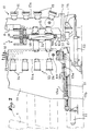
- the machine shown in fig. 1 comprises a vertical frame 1 suitably reinforced and guyed. Parallel to the amounts of this frame 1 are provided two columns 2 along which a movable head 3 slides, actuated using hydraulic cylinders 4.
- the frame 1 supports also two threaded rods 5 oriented vertically and driven in rotation at their base by a gear motor 6 associated with a horizontal connecting shaft 6a. These rods 5 ensure the vertical displacement of a double cross 7 associated with an actuating motor 8 for the usual maneuver flaring cones intended to give the free ends battery tubes a flared profile for easy connection of said tubes.
- carriages 9 are placed which slide along the columns 2 to guide the expansion rods 10 carried by head 3, which carriages are in known manner linked to each other by flexible links.
- the vertical frame 1 is associated with a pivoting loading deck 11. At its end facing the frame 1, this deck 11 is equipped with a fixed nose 12 intended to form a support for the batteries to be expanded.
- hydraulic cylinders 13 carried by the frame 1 ensure the tilting of the deck 11, of the horizontal orientation according to FIG. 1 in the vertical orientation according to fig. 2, by pivoting around two lateral axes referenced 14 in FIG. 2.
- the deck 11 is provided with a series of plates 15 that side chains 15 a connect to each other, said chains being driven in translation by an electric motor (not shown). These plates 15 are intended to support the batteries to be expanded, held laterally by adjustable tabs 16 (cf. fig. 1).
- the fixed nose 12 comprises a series of perforations 12 a for the insertion of the fixing plugs 17 a of a series of removable shoes 17.
- each shoe 17 is hollowed out with a cavity 17 b with concave bottom, suitable for forming housing for the elbows 18 a provided projecting on one of the end faces of the finned batteries 18.
- a sensor or contactor is provided electric C fixed on the rear face of the fixed nose 12.
- the machine comprises a retractable storage magazine 19.
- the base of this magazine 19 is provided with four pads 19 a and a ball nut 19 b .
- Each shoe 19 has engaged in a horizontal guide 20, while the ball nut 19b cooperates with a horizontal screw control 21.
- the screw 21 is rotated by a geared motor 22, and it is understood that the operation of this screw 21 ensures the horizontal movement of the magazine 19 in one direction or the other by means of an appropriate control of the motor mechanism 21-22.
- the front face of the magazine 19 is equipped with an eclipsable backsplash device 23 similar to that which equips the deck 11, in that it is formed by a series of plates 24 connected to each other by two side chains 24 has been properly driven in translation. As illustrated in fig. 2, in the raised position of the deck 11, the plates 15 and 24 come to retain the battery 18 during expansion, this battery bearing against the fixed nose 12 by means of the shoes 17, being oriented along the axis vertical movement of the movable head 3 and the double cross 7.
- the magazine 19 comprises a series of vertical tubes 25 (FIG. 4) in a number equal to the maximum number of expansion rods 10 capable of being fixed to the movable head 3; these tubes 25 are made rigidly integral with the upper and lower crosspieces of the magazine 19, and each of them is intended to form housing for a rod 10.
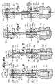
- each rod 10 is hollowed out at the top of an annular groove 10 a which defines an overhanging head 10 b , while its lower end comprises in the usual manner a projecting olive 10 c for the expansion of the battery tubes treat.
- the latter For fixing the upper part of the rods 10 on the movable head 3, the latter is provided with a movable locking plate 26 which slides horizontally in the thickness of said head 3, under the effect of an actuator 27 such than a small cylinder.
- This plate 26 is cut from a series of openings 26 a in number equal to that of the rods 10, each of these openings 26 a having the buttonhole profile which appears in FIG. 4 a .
- each of the rods 10 is capable of coming to engage in a blind vertical housing 3 practiced for this purpose in the head 3, while when said rod has been inserted into one of the tubes 25 of the magazine 19, its projecting lower part is introduced into a vertical housing 19 c of the base of the magazine 19, the lower end of each tube 25 being fitted into the upper outlet of the corresponding housing 19 c .
- a movable locking plate 28 identical to the plate 26 above indicated.
- each housing 19 c protrudes the end of the movable rod of a small selection cylinder 30.
- Each cylinder 30, arranged vertically in a block 31 secured to the base of the magazine 19, is placed under the dependence of one of the sensors C of the fixed nose 12, as illustrated in FIG. 3. Things are arranged in such a way that the rod of the jacks 30 corresponding to the sensors C actuated by the plugs 17a of the shoes 17 fixed on the nose 12, is pushed vertically to adopt the high position illustrated in FIG. 7, said jacks 30 being supplied through independent solenoid valves mounted in a general distributor 32 and connected to said sensors C.
- the gear motor 22 is actuated to advance the magazine 19 (cf. fig. 9) which is placed in the sliding axis of the head 3 and the double cross member 7.
- the movable head 3 is lowered so that the rods 10 which are fixed to it are engaged axially in the tubes 25 of the magazine 19 in the advanced position.
- the movable head 3 is then controlled over a short height upwards (FIG. 6) at the same time as the jack 29 is supplied so that the bottom plate 28 locks and retains all the rods 10 in the magazine 19. Then the jacks of selection 30 are supplied so that the rod of those which correspond to the sensors C controlled by the shoes 17 push upwards the corresponding rods 10 (fig. 7).
- the plate 26 is placed under the head 10b of the only rods 10 which have been selected, which has the effect of making the latter integral with the movable head 3.
- This head 3 can consequently move upwards (fig. 11) by driving the selected rods in its course.
- Head 3 is raised to its upper end-of-travel in order to take the rods 10 out of the tubes 25 from the magazine 19. The latter can then return to its retracted position (fig. 12).
- the plates 15 are positioned on the deck 11 and the device backrest 23 is brought towards the front of the storage unit 19 in depending on the height of the new battery to be treated.
- the movable head 3 can finally move downwards (fig. 13), the rods 10 which it carries ensuring by their olive 10 c the expansion of the tubes of said battery 18 and, at the end of movement and by vertical displacement of the cones carried by the double cross member 7, the flaring of the upper ends of the tubes of this battery.
Landscapes
- Engineering & Computer Science (AREA)
- Mechanical Engineering (AREA)
- Secondary Cells (AREA)
- Warehouses Or Storage Devices (AREA)
- Battery Mounting, Suspending (AREA)
Description
- Fig. 1 est une vue en perspective montrant schématiquement l'agencement général d'une machine suivant l'invention, représentée à la position de chargement, prête à recevoir une batterie à dilater ;
- Fig. 2 est une coupe verticale schématique montrant à plus grande échelle la partie inférieure de la machine suivant fig. 1, avec la batterie représentée en cours de dilatation ;
- Fig. 3 illustre la mise en place, sur le nez fixe, des sabots qui assurent la sélection des tiges de dilatation en fonction de la conformation des batteries à dilater ;
- Fig. 4 à 7 sont des coupes verticales de détail représentant le verrouillage et le déverrouillage des tiges sur la tête mobile et dans le magasin de stockage, ainsi que la sélection de ces tiges ;
- Fig. 8 à 13 sont des schémas illustrant le déplacement des organes mobiles de la machine lors de l'adaptation de celle-ci à la dilatation d'une batterie ailetée d'un type différent.
Claims (8)
- Machine pour la dilatation des tubes des batteries d'échange thermique du type aileté, du genre comprenant une tête mobile (3) qui, montée à coulissement sur un bâti fixe (1), est équipée d'une série de tiges démontables (10) pourvues d'une olive de dilatation (10c) apte, moyennant déplacement de ladite tête (3), à être introduite à force à l'intérieur des tubes d'une batterie (18) maintenue en appui contre un nez fixe de retenue (12), caractérisée en ce qu'elle comprend en outre un magasin mobile de stockage (19) associé à un mécanisme moteur (21-22) qui, lors de chaque modification apportée au nombre de tiges (10), intervient pour amener ledit magasin (19) suivant l'axe de coulissement de la tête (3) afin de recevoir toutes les tiges (10) après déverrouillage de celles-ci sur cette tête, tandis que des moyens de sélection (C, 30) sont prévus pour agir sur les tiges (10) à l'état stocké qui doivent à nouveau être rendues solidaires de la tête (3) et qui sont automatiquement verrouillées sur celle-ci, laquelle tête est à nouveau déplacée pour dégager les tiges sélectionnées hors du magasin que le mécanisme moteur (21-22) ramène enfin à la position escamotée permettant l'opération de dilatation.
- Machine suivant la revendication 1, caractérisée en ce que le mécanisme moteur associé au magasin escamotable (19) comprend un moto-réducteur (22) qui actionne une vis de commande (21) coopérant avec un écrou à billes (19b) porté par la base dudit magasin (19).
- Machine suivant l'une quelconque des revendications 1 et 2, caractérisée en ce que les moyens de sélection comprennent des capteurs on contacteurs électrique (C) fixés contre le nez fixe (12) au droit de perforations (12a) destinées à recevoir les fiches (17a) d'une série de sabots amovibles (17) conformés pour former logements pour les coudes (18a) des batteries (18) à dilater.
- Machine suivant la revendication 3, caractérisée en ce que les moyens de sélection comprennent également une série de vérins (30) placés sous la dépendance des capteurs (C) et agencés de façon à ce que leur tige mobile repousse les tiges de dilatation (10) qui-correspondent aux sabots (17).
- Machine suivant l'une quelconque des revendications 1 à 4, caractérisée en ce que le nez fixe (12) est fixé sur un tablier pivotant de chargement (11) équipé de plaques mobiles (15) formant supports pour la batterie à dilater (18).
- Machine suivant la revendication 5, caractérisée en ce que le magasin de stockage (19) est équipé d'un dosseret éclipsable (23) formé par des plaques mobiles (24) aptes à coopérer avec les plaques mobiles (15) du tablier pivotant (11) pour maintenir la batterie (18) en cours de dilatation.
- Machine suivant l'une quelconque des revendications 1 à 6, caractérisée en ce que le verrouillage des tiges de dilatation (10) sur la tête mobile (3) est opéré à l'aide d'une plaque mobile (26) associée à un actionneur (27) et découpée d'une série d'ouvertures (26a) en nombre égal à celui desdites tiges, chacune de ces ouvertures présentant un profil en forme de boutonnière apte à coopérer avec une gorge annulaire (10a) prévue à cet effet au sommet de chaque tige.
- Machine suivant la revendication 7, caractérisée en ce que pour la retenue, à l'intérieur du-magasin (19), des tiges (10) qui n'ont pas été sélectionnées, ledit magasin est équipé d'une plaque mobile de verrouillage (28) et d'un actionneur (29) identiques à celle (26) et à celui (27) de la tête mobile (3).
Applications Claiming Priority (2)
| Application Number | Priority Date | Filing Date | Title |
|---|---|---|---|
| FR9701027A FR2758750B1 (fr) | 1997-01-27 | 1997-01-27 | Machine a magasin escamotable de stockage pour la dilatation des tubes des batteries d'echange thermique du type ailete |
| FR9701027 | 1997-01-27 |
Publications (2)
| Publication Number | Publication Date |
|---|---|
| EP0860224A1 EP0860224A1 (fr) | 1998-08-26 |
| EP0860224B1 true EP0860224B1 (fr) | 2000-12-06 |
Family
ID=9503144
Family Applications (1)
| Application Number | Title | Priority Date | Filing Date |
|---|---|---|---|
| EP19980420013 Expired - Lifetime EP0860224B1 (fr) | 1997-01-27 | 1998-01-23 | Machine à magasin escamotable de stockage pour la dilatation des tubes des batteries d'échange thermique du type aileté |
Country Status (4)
| Country | Link |
|---|---|
| EP (1) | EP0860224B1 (fr) |
| DE (1) | DE69800417T2 (fr) |
| ES (1) | ES2152740T3 (fr) |
| FR (1) | FR2758750B1 (fr) |
Families Citing this family (4)
| Publication number | Priority date | Publication date | Assignee | Title |
|---|---|---|---|---|
| IT1315764B1 (it) * | 2000-12-07 | 2003-03-18 | C M S Costruzione Macchine Spe | Struttura di mandrinatrice verticale. |
| CN108817244A (zh) * | 2018-08-10 | 2018-11-16 | 珠海格力智能装备有限公司 | 悬挂机构及具有其的胀管机 |
| CN118023417A (zh) * | 2023-12-23 | 2024-05-14 | 广东博益空调配套设备有限公司 | 一种立式胀管机 |
| CN120715078B (zh) * | 2025-08-21 | 2025-10-31 | 湖南省怡昌力狮机器有限公司 | 一种发电机组底座折弯加工装置 |
Family Cites Families (4)
| Publication number | Priority date | Publication date | Assignee | Title |
|---|---|---|---|---|
| FR2369033A1 (fr) * | 1976-10-28 | 1978-05-26 | Chausson Usines Sa | Proce |
| US4738130A (en) * | 1985-11-08 | 1988-04-19 | Kyoshin Kogyo Kabushiki Kaisha | Structure for mounting mandrels in tube expanding apparatus |
| IT1264434B1 (it) * | 1992-06-12 | 1996-09-23 | Burr Oak Tool & Gauge | Espansore meccanico per tubi, con controllo su quattro assi |
| US5432994A (en) * | 1993-03-02 | 1995-07-18 | Kyoshin Kogyo Co. Ltd. | Tube expander with a means for transporting heat exchangers in tube expanding process |
-
1997
- 1997-01-27 FR FR9701027A patent/FR2758750B1/fr not_active Expired - Fee Related
-
1998
- 1998-01-23 ES ES98420013T patent/ES2152740T3/es not_active Expired - Lifetime
- 1998-01-23 EP EP19980420013 patent/EP0860224B1/fr not_active Expired - Lifetime
- 1998-01-23 DE DE1998600417 patent/DE69800417T2/de not_active Expired - Fee Related
Also Published As
| Publication number | Publication date |
|---|---|
| ES2152740T3 (es) | 2001-02-01 |
| DE69800417T2 (de) | 2001-04-19 |
| EP0860224A1 (fr) | 1998-08-26 |
| FR2758750B1 (fr) | 1999-03-12 |
| DE69800417D1 (de) | 2001-01-11 |
| FR2758750A1 (fr) | 1998-07-31 |
Similar Documents
| Publication | Publication Date | Title |
|---|---|---|
| EP0597077B1 (fr) | Outillage de prehension pour l'usinage de pieces sur une machine-outil | |
| EP1029619B1 (fr) | Ravitailleur de barres courtes pour machine-outil | |
| FR2677287A1 (fr) | Appareil de changement d'outils pour une poinconneuse a tourelle. | |
| FR2580973A1 (fr) | Procede et dispositif d'assemblage destines notamment aux lignes capacitaires de carrosseries | |
| EP0900612A1 (fr) | Dispositif d'alimentation automatique de barres, notamment pour tour CNC | |
| FR2563451A1 (fr) | Appareil pour l'assemblage d'un echangeur de chaleur a ailettes | |
| EP3363553A1 (fr) | Machine de roulage de tôles, ainsi que procédé de roulage d'une tôle utilisant une telle machine de roulage | |
| EP0526329B1 (fr) | Machine pour la pose automatique de segments sur des pistons | |
| FR2588791A1 (fr) | Dispositif pour transferer et positionner des pieces dans une machine a outils multiples synchronises | |
| CA1291697C (fr) | Machine pour le cintrage de tubes, barres ou profiles | |
| EP0860224A1 (fr) | Machine à magasin escamotable de stockage pour la dilatation des tubes des batteries d'échange thermique du type aileté | |
| EP0105779B1 (fr) | Dispositif et procédé de soudage d'éléments de structure d'assemblage de combustible nucléaire | |
| EP0010004B1 (fr) | Procédé et appareil pour la mise en place et le démontage des chambres dites "increvables" équipant certains pneumatiques | |
| EP0037343A2 (fr) | Procédé de réalisation d'une liasse apte à la formation d'au moins un classeur à soufflet, et machine pour la mise en oeuvre d'un tel procédé | |
| EP0296069B1 (fr) | Machine à brocher | |
| EP0072765B1 (fr) | Dispositif de changement d'outillage de laminoir à pas de pélerin | |
| FR2631099A1 (fr) | Dispositif de positionnement de pieces metalliques contre un element metallique porteur allonge | |
| FR3132907A1 (fr) | Portique de levage et procede de montage associe | |
| JP2832615B2 (ja) | キング嵌着装置 | |
| FR2732857A1 (fr) | Dispositif de recouvrement des graines implantees dans le sol destine a equiper un semoir agricole | |
| FR2715339A1 (fr) | Procédé et dispositif d'assemblage d'une carrosserie automobile. | |
| EP0783929B1 (fr) | Machine pour la dilatation des tubes de batterie d'échange thermique du type ailetté | |
| EP0589792B1 (fr) | Dispositif de manutention de faisceaux tubulaires pour échangeurs thermiques | |
| WO2008155476A1 (fr) | Outil de positionnement de côtés de caisse de véhicule sur une ligne d'assemblage, et son utilisation | |
| FR2624643A1 (fr) | Appareil et procede de separation d'embout d'assemblage combustible nucleaire |
Legal Events
| Date | Code | Title | Description |
|---|---|---|---|
| PUAI | Public reference made under article 153(3) epc to a published international application that has entered the european phase |
Free format text: ORIGINAL CODE: 0009012 |
|
| AK | Designated contracting states |
Kind code of ref document: A1 Designated state(s): DE ES FR IT |
|
| AX | Request for extension of the european patent |
Free format text: AL;LT;LV;MK;RO;SI |
|
| 17P | Request for examination filed |
Effective date: 19981116 |
|
| AKX | Designation fees paid |
Free format text: DE ES FR IT |
|
| RBV | Designated contracting states (corrected) |
Designated state(s): DE ES FR IT |
|
| GRAG | Despatch of communication of intention to grant |
Free format text: ORIGINAL CODE: EPIDOS AGRA |
|
| 17Q | First examination report despatched |
Effective date: 20000417 |
|
| GRAG | Despatch of communication of intention to grant |
Free format text: ORIGINAL CODE: EPIDOS AGRA |
|
| GRAH | Despatch of communication of intention to grant a patent |
Free format text: ORIGINAL CODE: EPIDOS IGRA |
|
| GRAH | Despatch of communication of intention to grant a patent |
Free format text: ORIGINAL CODE: EPIDOS IGRA |
|
| GRAA | (expected) grant |
Free format text: ORIGINAL CODE: 0009210 |
|
| AK | Designated contracting states |
Kind code of ref document: B1 Designated state(s): DE ES FR IT |
|
| REF | Corresponds to: |
Ref document number: 69800417 Country of ref document: DE Date of ref document: 20010111 |
|
| REG | Reference to a national code |
Ref country code: ES Ref legal event code: FG2A Ref document number: 2152740 Country of ref document: ES Kind code of ref document: T3 |
|
| ITF | It: translation for a ep patent filed | ||
| PLBE | No opposition filed within time limit |
Free format text: ORIGINAL CODE: 0009261 |
|
| STAA | Information on the status of an ep patent application or granted ep patent |
Free format text: STATUS: NO OPPOSITION FILED WITHIN TIME LIMIT |
|
| 26N | No opposition filed | ||
| PGFP | Annual fee paid to national office [announced via postgrant information from national office to epo] |
Ref country code: FR Payment date: 20021128 Year of fee payment: 6 |
|
| PGFP | Annual fee paid to national office [announced via postgrant information from national office to epo] |
Ref country code: ES Payment date: 20021223 Year of fee payment: 6 |
|
| PGFP | Annual fee paid to national office [announced via postgrant information from national office to epo] |
Ref country code: DE Payment date: 20030108 Year of fee payment: 6 |
|
| PG25 | Lapsed in a contracting state [announced via postgrant information from national office to epo] |
Ref country code: ES Free format text: LAPSE BECAUSE OF NON-PAYMENT OF DUE FEES Effective date: 20040124 |
|
| PG25 | Lapsed in a contracting state [announced via postgrant information from national office to epo] |
Ref country code: DE Free format text: LAPSE BECAUSE OF NON-PAYMENT OF DUE FEES Effective date: 20040803 |
|
| PG25 | Lapsed in a contracting state [announced via postgrant information from national office to epo] |
Ref country code: FR Free format text: LAPSE BECAUSE OF NON-PAYMENT OF DUE FEES Effective date: 20040930 |
|
| REG | Reference to a national code |
Ref country code: FR Ref legal event code: ST |
|
| PG25 | Lapsed in a contracting state [announced via postgrant information from national office to epo] |
Ref country code: IT Free format text: LAPSE BECAUSE OF NON-PAYMENT OF DUE FEES;WARNING: LAPSES OF ITALIAN PATENTS WITH EFFECTIVE DATE BEFORE 2007 MAY HAVE OCCURRED AT ANY TIME BEFORE 2007. THE CORRECT EFFECTIVE DATE MAY BE DIFFERENT FROM THE ONE RECORDED. Effective date: 20050123 |
|
| REG | Reference to a national code |
Ref country code: ES Ref legal event code: FD2A Effective date: 20040124 |