EP0860236A2 - Machine de tribo-finition centrifuge - Google Patents
Machine de tribo-finition centrifuge Download PDFInfo
- Publication number
- EP0860236A2 EP0860236A2 EP98102679A EP98102679A EP0860236A2 EP 0860236 A2 EP0860236 A2 EP 0860236A2 EP 98102679 A EP98102679 A EP 98102679A EP 98102679 A EP98102679 A EP 98102679A EP 0860236 A2 EP0860236 A2 EP 0860236A2
- Authority
- EP
- European Patent Office
- Prior art keywords
- container
- grinding machine
- machine according
- gap
- bottom part
- Prior art date
- Legal status (The legal status is an assumption and is not a legal conclusion. Google has not performed a legal analysis and makes no representation as to the accuracy of the status listed.)
- Granted
Links
Images

Classifications
-
- B—PERFORMING OPERATIONS; TRANSPORTING
- B24—GRINDING; POLISHING
- B24B—MACHINES, DEVICES, OR PROCESSES FOR GRINDING OR POLISHING; DRESSING OR CONDITIONING OF ABRADING SURFACES; FEEDING OF GRINDING, POLISHING, OR LAPPING AGENTS
- B24B31/00—Machines or devices designed for polishing or abrading surfaces on work by means of tumbling apparatus or other apparatus in which the work and/or the abrasive material is loose; Accessories therefor
- B24B31/10—Machines or devices designed for polishing or abrading surfaces on work by means of tumbling apparatus or other apparatus in which the work and/or the abrasive material is loose; Accessories therefor involving other means for tumbling of work
- B24B31/108—Machines or devices designed for polishing or abrading surfaces on work by means of tumbling apparatus or other apparatus in which the work and/or the abrasive material is loose; Accessories therefor involving other means for tumbling of work involving a sectioned bowl, one part of which, e.g. its wall, is stationary and the other part of which is moved, e.g. rotated
Definitions
- the invention relates to a centrifugal vibratory grinding machine with a bowl-like rotatable container bottom part and a stationary, substantially cylindrical Container top.
- Centrifugal vibratory grinding machines are used for surface processing especially of smaller parts and Workpieces use together with grinding tools and optionally a liquid processing agent in be moved in a container.
- a centrifugal slide grinding machine an upwardly opening, shell-like bottom part, that is rotated around a vertical axis.
- Above the bottom part is a cylindrical container top arranged stationary, with its lower edge on the upper edge of the bottom part with the interposition of a Seal rests.
- the bottom part rotates the workpieces to be treated are in the bottom part acted radially outward until it reaches the Hit the inner wall of the stationary upper part of the container, at which they are slowed down.
- Inflowing Workpieces are subject to a radially rotating workpiece movement one that intensive grinding causes.
- the transition area between the top of the rotating Bottom part and the bottom of the stationary The upper part of the container is very susceptible to wear. It is therefore, attempts have been made between these two Components effective seal as slip ring seal form, the at the bottom part and / or the Ceramic slip ring arranged in the upper part of the container consists. In this way, the seal can Reduce wear that occurs, however Ceramic rings of larger diameter very expensive and it Another problem arises that the diameter of the Ceramic rings and thus the diameter of the upper part of the container Technically limited to a maximum of approx. 50 cm is, so that such a centrifugal vibratory grinding machine in their volume and also in their work performance is subject to severe restrictions. It is An attempt has been made to make a ceramic ring out of several ceramic ones Put together ring segments, kicked however, problems with sealing.
- DE-PS 44 28 817 is between the two Component effective seal through a hardened steel ring on the bottom part and a felt ring on the top of the container educated.
- the felt ring can be used Incorporation of fine grinding media into the felt, see above arises at the contact surface between the two ring seals a gap that is not due to the felt seal can be more balanced. This and the wear due to the friction on the contact surfaces between Container top and bottom part then leads to the smallest parts can no longer be edited.
- the invention is therefore based on the object Centrifugal slide grinder to create the most reliable works, has a long service life, nevertheless but allows an absolutely dry grinding.
- the stated object is achieved with a Centrifugal vibratory grinding machine of the aforementioned Type solved, which is characterized in that the container bottom and top at their opposite End faces are each provided with a ceramic part.
- the hard ceramic parts which are preferably ring-shaped, are designed as rings, it is ensured that even if the upper part of the container is tilted No welding of the boundary surfaces to the lower part of the container of the bottom and top of the container, but permanent smooth rotatability the upper part is ensured relative to the lower part.
- there is a finite gap between the ceramic parts is.
- the gap size will usually be such that they in the range of the particle size or slightly below this lies so that particles do not pass through the gap from the Can penetrate outside of the grinding machine.
- the ceramic rings By forming the ceramic rings on the lower part of the container and on the upper face of the container bottom part it also ensures that in case of intrusion a very small abrasive particle in the gap, whereby the above-mentioned edging can only be done due to the relative rotational movement between the upper and lower part the particle is crushed, but not the above Damage can occur, such as in Metal would be used.
- the gap is adjustable. This allows the gap width adapted to the size of the abrasive particles used will. See further preferred configurations before that the gap has a size of 0.05-0.5 mm and in particular that the gap is approx. 0.3 mm, whereby of course to be observed is that the gap is not larger than the (minimum) Dimensions of the abrasive particles should be.
- the adjustability of the gap can be different Be done, for example by washers or the like.
- An extremely preferred embodiment but provides that the gap can be adjusted using adjusting screws is, in particular the set screws on Circumference of the upper part of the container and one carrying it Carrying part are arranged.
- the inner wall of the upper part of the container is in her lower end section tapers radially inwards.
- the upper part of the container a relatively large one over most of its height Can have a diameter that is due to the conical Design of the lower end area into one reduced lower margin with a much smaller diameter.
- the diameter of the bottom is the necessary Determines the size or diameter of the seal, can with the centrifugal slide grinding machine according to the invention one-piece slip rings made of ceramic use find, although the container top is a relatively large Volume and thus a high work rate.
- the between the two inner walls of the bottom part and Angle of the container upper part kept small be, so that from a deflection of the to be processed Workpieces resulting load is low.
- the inner walls of container top and bottom part in the area of the gap.
- the inner wall of the bottom part goes smoothly into the inner wall of the upper part of the container about.
- the contact surface between the lower edge of the upper part of the container and the top of the bottom part are different Alternatives conceivable.
- the gap clearly under one angle deviating from a right angle to the Inner walls of the top and bottom part of the container is aligned, in particular the gap essentially aligned horizontally or perpendicular to the axis of rotation is. This causes an axial movement of the upper part of the container or bottom part evenly on the contact surface.
- the gap below at a right angle to the inner walls of the upper part of the container and floor part is aligned.
- the outer part the bottom part of the container is preferably made of aluminum or an aluminum alloy. The same can be done for the top of the container should be the case.
- the lining consists preferably of polyurethane.
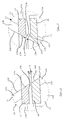
- the centrifugal slide grinding machine 10 has a on a machine carrier, not shown attached outer, housing-like support member 11. At the Support part 11 is rotatable via a bearing 11a Container bottom part rotatable about its drive axis 12a stored. The container bottom part 12 is on the axis 12a driven by a drive, not shown.
- a container upper part 13 Sitting on the upper edge 11b of the support member 11 with the support member 11 connected, a container upper part 13.
- the container upper part is with the support member 11 via adjusting screws 14 connected and by means of these screws in his Height adjustable in the direction of the axis of rotation D.
- the screws 14 with their heads 16 each on one flange arranged radially on the outside of the container upper part 13 13d on which the screws 14 with their threaded bolts protrude.
- the container upper part 13 has a metallic outer part 13a on the inside with a coating 13b is provided.
- the outer part 13a has one circular cylindrical shape and is on its inner wall tapers radially inwards.
- the coating 13b essentially follows this conical configuration, see above that the lower edge of the container upper part 13 one smaller inner diameter than the one above it essentially circular cylindrical section of the upper part of the container 13 has.
- an annular ceramic part 17 At the lower end of the container upper part 13 is attached an annular ceramic part 17, the front 17a with the inner wall 13f of the coating 13b of the container upper part 13 is aligned. In the front area the ceramic part 17 has a downward nose 17b.
- the bottom part 12 also has a metallic outer part 12a and a coating 12b.
- a metallic outer part 12a In the top of the container 13 adjacent area has the outer part 12a of the bottom part 12 a flared Inner wall 12c.
- the outer part 12a of the bottom part 12 is also provided with a coating 12b and the inner wall 12f essentially follows the inner wall 12c of the outer part 12a.
- the bottom part 12 In the top of the container 13 facing area is the bottom part 12 also provided with an annular ceramic part 18, whose inner wall 18a with the inner wall 17a - and also the inner wall 12f of the coating 12b - is aligned.
- an adjustable slot S with a finite one Slot width formed by the size of the used Abrasive material depends, but preferably in is of the order of 0.3 mm.
- the top runs 18b and the underside of the nose 17b essentially horizontally and therefore at an angle not equal to 90 ° the inner walls 13f, 17a, 18a, 12f.
- FIG. 3 corresponds essentially that of Fig. 2.
- a difference is that the Top 18b of the ceramic part 18 from the outside inwards is angled upwards.
- the bottom the nose 17b is parallel to the front or inner area of the upper side 18b of the ceramic part 18.
- the slot S is thus in the embodiment of FIG. 3 aligned so that it is at right angles to the Forms inner walls 13f, 17a, 18a, 12f.
Landscapes
- Engineering & Computer Science (AREA)
- Mechanical Engineering (AREA)
- Finish Polishing, Edge Sharpening, And Grinding By Specific Grinding Devices (AREA)
- Grinding And Polishing Of Tertiary Curved Surfaces And Surfaces With Complex Shapes (AREA)
- Food-Manufacturing Devices (AREA)
- Centrifugal Separators (AREA)
Applications Claiming Priority (2)
| Application Number | Priority Date | Filing Date | Title |
|---|---|---|---|
| DE29702859U | 1997-02-19 | ||
| DE29702859U DE29702859U1 (de) | 1997-02-19 | 1997-02-19 | Fliehkraft-Gleitschleifmaschine |
Publications (3)
| Publication Number | Publication Date |
|---|---|
| EP0860236A2 true EP0860236A2 (fr) | 1998-08-26 |
| EP0860236A3 EP0860236A3 (fr) | 2000-02-02 |
| EP0860236B1 EP0860236B1 (fr) | 2002-07-17 |
Family
ID=8036153
Family Applications (1)
| Application Number | Title | Priority Date | Filing Date |
|---|---|---|---|
| EP98102679A Expired - Lifetime EP0860236B1 (fr) | 1997-02-19 | 1998-02-17 | Machine de tribo-finition centrifuge |
Country Status (4)
| Country | Link |
|---|---|
| US (1) | US6296556B1 (fr) |
| EP (1) | EP0860236B1 (fr) |
| DE (2) | DE29702859U1 (fr) |
| ES (1) | ES2178791T3 (fr) |
Cited By (3)
| Publication number | Priority date | Publication date | Assignee | Title |
|---|---|---|---|---|
| WO2001064393A1 (fr) * | 2000-02-29 | 2001-09-07 | Otec Präzisionsfinish GmbH | Rectifieuse |
| DE202013002000U1 (de) | 2013-03-04 | 2014-03-13 | Otec Präzisionsfinish GmbH | Fliehkraft-Gleitschleifmaschine |
| CN107614198A (zh) * | 2015-05-18 | 2018-01-19 | 阿特拉斯·科普柯·塞科洛克有限公司 | 用于对钻头球齿的韧性和硬度进行处理的方法 |
Families Citing this family (8)
| Publication number | Priority date | Publication date | Assignee | Title |
|---|---|---|---|---|
| DE19912348A1 (de) * | 1999-03-19 | 2000-09-28 | Gegenheimer Helmut | Schleifmaschine |
| DE20009539U1 (de) * | 2000-05-26 | 2001-08-02 | OTEC Präzisionsfinish GmbH, 75334 Straubenhardt | Vorrichtung zum Schleifen von Schleifgut |
| DE20018805U1 (de) * | 2000-11-03 | 2001-01-04 | OTEC Präzisionsfinish GmbH, 75334 Straubenhardt | Schleifmaschine |
| JP2005021810A (ja) * | 2003-07-02 | 2005-01-27 | Tipton Mfg Corp | コーティング装置 |
| US7871307B2 (en) * | 2005-02-15 | 2011-01-18 | Sintokogio, Ltd. | Fluid barrel-polishing device and polishing method |
| DE102013204816A1 (de) | 2013-03-19 | 2014-09-25 | Rösler Holding GmbH & Co. KG | Gleitschliffmaschine und verfahren zur spalteinstellung |
| CN204525132U (zh) * | 2015-04-23 | 2015-08-05 | 浙江湖磨抛光磨具制造有限公司 | 无缝隙流动式光饰机 |
| CN105538122A (zh) * | 2016-01-21 | 2016-05-04 | 浙江湖磨抛光磨具制造有限公司 | 无缝干式流动光饰方法及流动光饰机 |
Family Cites Families (11)
| Publication number | Priority date | Publication date | Assignee | Title |
|---|---|---|---|---|
| DE3604619A1 (de) * | 1986-02-14 | 1987-08-20 | Spaleck Gmbh Max | Fliehkraftbearbeitungsmaschine |
| US5012620A (en) * | 1987-10-06 | 1991-05-07 | Roto-Finish Company, Inc. | Centrifugal finishing apparatus embodying improved seal and method |
| DE3802542C1 (fr) * | 1988-01-28 | 1989-08-24 | Max Spaleck Gmbh & Co Kg, 4290 Bocholt, De | |
| DE3812908A1 (de) * | 1988-04-18 | 1989-10-26 | Walther Carl Kurt Gmbh | Fliehkraft-gleitschleifmaschine |
| JPH075974Y2 (ja) * | 1990-04-06 | 1995-02-15 | 株式会社チップトン | 渦流バレル加工機 |
| US5279074A (en) * | 1990-08-28 | 1994-01-18 | The Grav-I-Flo Corporation | Centrifugal disk finishing apparatus utilizing dry media |
| DE4038253A1 (de) * | 1990-11-30 | 1992-06-04 | Spaleck Gmbh Max | Fliehkraftbearbeitungsmaschine |
| DE4214060A1 (de) * | 1992-04-29 | 1993-11-04 | Peter Dannemann | Vorrichtung zum entgraten, schleifen und polieren von schuettguetern aller art |
| US5476415A (en) * | 1993-10-22 | 1995-12-19 | Sintobrator, Ltd. | Dry barrel finishing machine |
| DE4428817C1 (de) * | 1994-02-09 | 1995-06-01 | Dreher Manfrid Kg Dr Ing | Fliehkraft-Gleitschleifmaschine |
| JP3062800B2 (ja) * | 1996-02-26 | 2000-07-12 | 株式会社チップトン | 渦流バレル加工機 |
-
1997
- 1997-02-19 DE DE29702859U patent/DE29702859U1/de not_active Expired - Lifetime
-
1998
- 1998-02-17 DE DE59804756T patent/DE59804756D1/de not_active Expired - Lifetime
- 1998-02-17 EP EP98102679A patent/EP0860236B1/fr not_active Expired - Lifetime
- 1998-02-17 ES ES98102679T patent/ES2178791T3/es not_active Expired - Lifetime
- 1998-02-18 US US09/025,234 patent/US6296556B1/en not_active Expired - Lifetime
Cited By (3)
| Publication number | Priority date | Publication date | Assignee | Title |
|---|---|---|---|---|
| WO2001064393A1 (fr) * | 2000-02-29 | 2001-09-07 | Otec Präzisionsfinish GmbH | Rectifieuse |
| DE202013002000U1 (de) | 2013-03-04 | 2014-03-13 | Otec Präzisionsfinish GmbH | Fliehkraft-Gleitschleifmaschine |
| CN107614198A (zh) * | 2015-05-18 | 2018-01-19 | 阿特拉斯·科普柯·塞科洛克有限公司 | 用于对钻头球齿的韧性和硬度进行处理的方法 |
Also Published As
| Publication number | Publication date |
|---|---|
| EP0860236A3 (fr) | 2000-02-02 |
| US6296556B1 (en) | 2001-10-02 |
| DE59804756D1 (de) | 2002-08-22 |
| EP0860236B1 (fr) | 2002-07-17 |
| DE29702859U1 (de) | 1998-03-19 |
| ES2178791T3 (es) | 2003-01-01 |
Similar Documents
| Publication | Publication Date | Title |
|---|---|---|
| DE60209235T2 (de) | Geprägte unterlagsscheibe | |
| EP0860236B1 (fr) | Machine de tribo-finition centrifuge | |
| EP0865878A2 (fr) | Meule type boisseau | |
| EP1493368B1 (fr) | Moulin à café pour une machine à café | |
| EP3356049B1 (fr) | Dispositif de traitement et élément de traitement et élément de revêtement de paroi pour un dispositif de traitement de ce type | |
| DE1502592A1 (de) | Laeppmaschine | |
| DE3719445A1 (de) | Stuetzscheibe fuer eine stuetzscheibenlagerung | |
| WO2001064394A1 (fr) | Rectifieuse | |
| DE20202998U1 (de) | Werkstücktisch zur Fräs- und Drehbearbeitung | |
| EP0129038B1 (fr) | Dispositif de palier pour fonctionnement sous l'eau ou en milieux boueux | |
| DE20018805U1 (de) | Schleifmaschine | |
| WO1998051447A1 (fr) | Meule de rectification pour lame scie circulaire metaux | |
| DE10032449A1 (de) | Schleifscheibe | |
| DE19929201A1 (de) | Werkzeug zur spanabhebenden Bearbeitung mindestens eines Werkstückes | |
| EP1525370A2 (fr) | Dispositif pour realiser des forages dans la terre | |
| EP2897774A1 (fr) | Dispositif de traitement de surface de planchers et de revêtements | |
| DE69213209T2 (de) | Lagerträger für Evolventenlager | |
| DE4314152C2 (de) | Vorrichtung zur Beseitigung der Schwingungsneigung eines Werkstückscheiben- oder Werkzeugträgers in Maschinen zur einseitigen Bearbeitung der Oberflächen von Halbleiterscheiben | |
| DE69008686T2 (de) | Pulverisiermühle. | |
| DE8901794U1 (de) | Vorrichtung zum Zerkleinern von Stahl- oder Metallspänen | |
| EP0067402A1 (fr) | Tête porte-meule pour roche dure | |
| DE4019029A1 (de) | Stuetzscheibe fuer eine stuetzscheibenlagerung fuer oe-spinnrotoren | |
| DE364258C (de) | Zerkleinerungsmaschine mit drehbarem Tisch und von dem letzteren getragenen einstellbaren Walzen, die gegen einen festen Mahlring ueber dem Tisch gepresst werden | |
| EP1701794B1 (fr) | Broyeur a disques | |
| DE10260420A1 (de) | Scheibenförmiges Entgratwerkzeug |
Legal Events
| Date | Code | Title | Description |
|---|---|---|---|
| PUAI | Public reference made under article 153(3) epc to a published international application that has entered the european phase |
Free format text: ORIGINAL CODE: 0009012 |
|
| AK | Designated contracting states |
Kind code of ref document: A2 Designated state(s): DE ES FR IT |
|
| AX | Request for extension of the european patent |
Free format text: AL;LT;LV;MK;RO;SI |
|
| PUAL | Search report despatched |
Free format text: ORIGINAL CODE: 0009013 |
|
| AK | Designated contracting states |
Kind code of ref document: A3 Designated state(s): AT BE CH DE DK ES FI FR GB GR IE IT LI LU MC NL PT SE |
|
| AX | Request for extension of the european patent |
Free format text: AL;LT;LV;MK;RO;SI |
|
| 17P | Request for examination filed |
Effective date: 20000429 |
|
| AKX | Designation fees paid |
Free format text: DE ES FR IT |
|
| 17Q | First examination report despatched |
Effective date: 20010213 |
|
| GRAG | Despatch of communication of intention to grant |
Free format text: ORIGINAL CODE: EPIDOS AGRA |
|
| GRAG | Despatch of communication of intention to grant |
Free format text: ORIGINAL CODE: EPIDOS AGRA |
|
| GRAH | Despatch of communication of intention to grant a patent |
Free format text: ORIGINAL CODE: EPIDOS IGRA |
|
| GRAH | Despatch of communication of intention to grant a patent |
Free format text: ORIGINAL CODE: EPIDOS IGRA |
|
| GRAA | (expected) grant |
Free format text: ORIGINAL CODE: 0009210 |
|
| AK | Designated contracting states |
Kind code of ref document: B1 Designated state(s): DE ES FR IT |
|
| REF | Corresponds to: |
Ref document number: 59804756 Country of ref document: DE Date of ref document: 20020822 |
|
| ET | Fr: translation filed | ||
| REG | Reference to a national code |
Ref country code: ES Ref legal event code: FG2A Ref document number: 2178791 Country of ref document: ES Kind code of ref document: T3 |
|
| PLBE | No opposition filed within time limit |
Free format text: ORIGINAL CODE: 0009261 |
|
| STAA | Information on the status of an ep patent application or granted ep patent |
Free format text: STATUS: NO OPPOSITION FILED WITHIN TIME LIMIT |
|
| 26N | No opposition filed |
Effective date: 20030422 |
|
| REG | Reference to a national code |
Ref country code: FR Ref legal event code: PLFP Year of fee payment: 19 |
|
| REG | Reference to a national code |
Ref country code: FR Ref legal event code: PLFP Year of fee payment: 20 |
|
| PGFP | Annual fee paid to national office [announced via postgrant information from national office to epo] |
Ref country code: FR Payment date: 20170227 Year of fee payment: 20 Ref country code: DE Payment date: 20170221 Year of fee payment: 20 |
|
| PGFP | Annual fee paid to national office [announced via postgrant information from national office to epo] |
Ref country code: IT Payment date: 20170217 Year of fee payment: 20 Ref country code: ES Payment date: 20170220 Year of fee payment: 20 |
|
| REG | Reference to a national code |
Ref country code: DE Ref legal event code: R071 Ref document number: 59804756 Country of ref document: DE |
|
| REG | Reference to a national code |
Ref country code: ES Ref legal event code: FD2A Effective date: 20180525 |
|
| PG25 | Lapsed in a contracting state [announced via postgrant information from national office to epo] |
Ref country code: ES Free format text: LAPSE BECAUSE OF EXPIRATION OF PROTECTION Effective date: 20180218 |