EP0860245B1 - Dispositif de pressage - Google Patents
Dispositif de pressage Download PDFInfo
- Publication number
- EP0860245B1 EP0860245B1 EP19980101788 EP98101788A EP0860245B1 EP 0860245 B1 EP0860245 B1 EP 0860245B1 EP 19980101788 EP19980101788 EP 19980101788 EP 98101788 A EP98101788 A EP 98101788A EP 0860245 B1 EP0860245 B1 EP 0860245B1
- Authority
- EP
- European Patent Office
- Prior art keywords
- pressing
- pressing tool
- movable
- tool according
- jaws
- Prior art date
- Legal status (The legal status is an assumption and is not a legal conclusion. Google has not performed a legal analysis and makes no representation as to the accuracy of the status listed.)
- Expired - Lifetime
Links
Images


Classifications
-
- H—ELECTRICITY
- H01—ELECTRIC ELEMENTS
- H01R—ELECTRICALLY-CONDUCTIVE CONNECTIONS; STRUCTURAL ASSOCIATIONS OF A PLURALITY OF MUTUALLY-INSULATED ELECTRICAL CONNECTING ELEMENTS; COUPLING DEVICES; CURRENT COLLECTORS
- H01R43/00—Apparatus or processes specially adapted for manufacturing, assembling, maintaining, or repairing of line connectors or current collectors or for joining electric conductors
- H01R43/04—Apparatus or processes specially adapted for manufacturing, assembling, maintaining, or repairing of line connectors or current collectors or for joining electric conductors for forming connections by deformation, e.g. crimping tool
- H01R43/042—Hand tools for crimping
- H01R43/0427—Hand tools for crimping fluid actuated hand crimping tools
-
- B—PERFORMING OPERATIONS; TRANSPORTING
- B25—HAND TOOLS; PORTABLE POWER-DRIVEN TOOLS; MANIPULATORS
- B25B—TOOLS OR BENCH DEVICES NOT OTHERWISE PROVIDED FOR, FOR FASTENING, CONNECTING, DISENGAGING OR HOLDING
- B25B27/00—Hand tools, specially adapted for fitting together or separating parts or objects whether or not involving some deformation, not otherwise provided for
- B25B27/02—Hand tools, specially adapted for fitting together or separating parts or objects whether or not involving some deformation, not otherwise provided for for connecting objects by press fit or detaching same
- B25B27/10—Hand tools, specially adapted for fitting together or separating parts or objects whether or not involving some deformation, not otherwise provided for for connecting objects by press fit or detaching same inserting fittings into hoses
Definitions
- the invention relates to a pressing device for connecting tubular workpieces, for example a pipe with a press fitting, with at least two press jaws surrounding a pressing chamber, of which at least two are movable relative to each other so that they are placed on the workpiece in an open position and for the pressing operation by means of a drive motor are movable into a closed position, wherein the or at least two of the movable cheek plates - directly or indirectly - are coupled such that upon actuation of a movable cheek and the other (n) movable cheek plate (n ) is moved in the same direction or be, and wherein the pressing device has on its housing a grip portion for a holding hand, which allows a holding of the pressing device.
- sleeve-shaped press fittings which are made of plastic or metal.
- the press fitting is slid over the pipe ends to make a pipe joint and then radially compressed in the overlapping areas, with both the press fitting and the pipe being plastically deformed become.
- Such pipe connections and the associated press fittings are known, for example, from EP-B 0 361 630.
- the pressing of the press fitting and the tube is done by means of pressing devices, as they are known in various embodiments, for example in DE-C 21 36 782, DE-A-34 23 283 and EP-A-0 451 806.
- the pressing devices consist of a pressing tool and a drive for the pressing tool.
- the pressing tool has at least two, in some cases also more cheek plates, of which at least two cheek plates are movable relative to each other. You can be moved in this way in an open position in which an attachment of the pressing device to the press fitting is possible. Subsequently, the cheek plates can be moved together with the help of the drive to a closed position.
- a drive hydraulic piston is often provided, which can be acted upon by a hand-operated or electric motor driven pump with hydraulic pressure. An electric drive is known.
- FR 2 528 750 A and GB 1 179 929 A presses are disclosed in which two movable cheek plates are coupled so that upon actuation of a cheek plate and the other movable cheek plate is moved in the same direction. Due to this coupling, the actuation of a single cheek plate to move both movable cheek plates either in the direction of the open position or in the direction of the closed position, which makes the operation of the pressing device easier and safer. Nevertheless, two hands are required to open the cheek plates.
- the invention is therefore based on the object to design a pressing device of the type mentioned so that the operation is simple and secure.
- a pressing device according to claim 1, wherein the handle portion is provided so that one of the movable cheek plates by means of the holding hand on the handle portion in the direction of the open position is movable, and that the pressing device comprises a switch for switching on the drive, the Griff Silvert is assigned such that it is actuated by a finger or thumb of the holding hand. Due to this assignment of the intended grip area, at least one of the movable press jaws and the switch for switching on the drive, the opening of the press jaws and the switching on can take place with one hand, which simplifies the handling of the pressing device. In addition, the handling is also safer, because the other hand is free to cling to ladders or the like, for example.
- the coupling of the cheek plates can be done in different ways.
- a coupling rod is used for this purpose, which is hinged to the cheek plates or associated parts such that the movement of a cheek plate is transferred to the other cheek so that both in the direction of either the open or the closed position and thus to move in the same direction, albeit usually in the opposite direction.
- the same effect can be achieved via a coupling friction or a coupling toothing.
- a kind of coupling toothing consists, for example, that the or at least two adjacent movable cheek plates have two opposite recesses in which a coupling element engages such that upon actuation of a Preßbakke and the other cheek plate is moved in the same direction.
- the coupled cheek plates are spring-loaded in the closing direction, so that they close themselves after applying the pressing device to the press fitting by itself. This also facilitates the handling of the pressing device.
- the cheek plates have in known manner drive lever or are connected to it, which can be acted upon by a drive in the closing direction, they should end adjacent to this handle area, so that they can be moved over the cheek plates in the open position.
- the above-described training allows a particularly convenient one-handed operation of the pressing device. The other hand is free either to hold the pipeline or to secure himself to a ladder or scaffolding.
- the handle portion is associated with an actuating lever, via which one of the movable cheek plates - possibly via the drive lever - in the direction of the open position can be acted upon.
- a blocking device for non-positive or positive blocking of at least one of the coupled cheek plates is provided in the open position.
- Such a blocking device is particularly useful if - as provided above - the coupled cheek plates are spring-loaded in the closing direction. After opening the cheek plates, it is then no longer necessary to hold the cheek plates in this position. It is understood that the blocking for the closing of the cheek plates must be canceled again.
- the blocking device can be designed in various ways. So there is the possibility to train them as magnets. If the movable cheek plates - as known per se - have drive lever or articulated with them, they can be provided with magnets which bear against each other in the open position of the cheek plates. Alternatively, the blocking device may also be designed as a movable blocking element, which is movable in the open position of the cheek plates in a blocking position. This may be locking elements, etc. In this case, the blocking element should be spring-loaded in the direction of the blocking position, so that it jumps on reaching the open position by itself in the blocking position.
- the pressing device has a gripping area for gripping the pressing device with one hand and the blocking element is assigned to the grip area such that it can be actuated by this hand.
- a movable sensor protrudes, which is coupled to the blocking device such that it causes a release of the Blokkier immunity when attaching the pressing device to the workpiece. In this way, an influence of the blocking device by hand is not necessary.
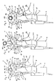
- the pressing device 1 shown in Figures 1 to 3 essentially consists of a drive 2 and a pressing tool 3.
- the drive 2 has an electric drive motor 4, which acts via a gear 5 on a movable in the longitudinal direction of the pressing device 1, hidden drive stamp, such as this results, for example, from DE-U-295 02 032.6.
- the drive 2 runs in the direction of the pressing tool 3 in a holding fork 6, which is arranged by a front fork piece 7 and at a distance behind it and therefore not visible second fork piece is formed. In the space between the two fork pieces 7 of the drive stamp is retractable.
- the fork pieces 7 are connected to each other via a bearing pin 8.
- This bearing pin 8 passes through two T-shaped bearing plates 9, of which only the front bearing plate lying in the views to see 9, while the rear, identical bearing plate is covered by the front bearing plate 9.
- the bearing plates 9 are each directly adjacent to the respective adjacent fork piece 7 and have a distance from each other.
- two mirror-formed press jaws 10, 11 are arranged and mounted on the bearing plates 9 pivotally mounted in the plane of the drawing via bearing pins 12, 13.
- the unit of bearing plates 9 and cheek plates 10, 11 with bearing pins 12, 13 form the pressing tool 3 and are separable as a whole by removing the bearing pin 8 of the drive 2. In this way can be attached to the drive 2 different sizes of pressing tools 3.
- the cheek plates 10, 11 have above the bearing pin 12, 13 jaw arms 14, 15, in the opposite jaw recesses 16, 17 are formed. Between the Preßbacken 10, 11 is a third cheek plate 19, which is fixed between the bearing plates 9, that is held immovable. Your jaw recess 20 completes the jaw recesses 16, 17 in such a way that in the closed state of the Preßtechnikmaschinees 3 a closed baling chamber 21 is formed.
- Figure 1 shows the position of the pressing device 1 before startup.
- the movable Preßbacken 10, 11 are due to a spring bias in the closed position.
- a hand 26 surrounds the housing of the drive 2 at a location provided immediately adjacent the free ends of the drive lever 22, 23, in such a way that the thumb 27 of the hand 26 can be placed on the outside of the right drive lever 23, without that thereby the handle is lost to the housing of the drive 2.
- the pressing device 1 can be attached to a pipe joint 28 transverse to the tube axis, the pressing chamber 21 is thereby opened at the top, that the right drive lever 23 by means of the thumb 27 is pivoted inwardly, ie clockwise. Due to a kinematic connection, not shown here, shown in more detail in the other figures The two cheek plates 10, 11, the pivoting movement of the right cheek plate 11 is transferred to the left cheek plate 10 such that they are pivoted in the opening direction, ie in the opposite direction and thus counterclockwise. In this way, the symmetrical open position of the cheek plates 10, 11 shown in Figure 2 is achieved. Between the free ends of the jaw arms 14, 15 results in a mouth-like opening, which is slightly larger than the diameter of the pipe joint 28, so that the pressing device 1 can be moved over this.
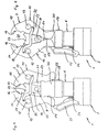
- a bearing pin 34 is pivotally mounted.
- the actuating lever 33 thus lies in the grip region of the fingers of the hand 26 and is surrounded by these when holding the pressing device 1 on the outside.
- At the upper end of the actuating lever 33 is located on the outside of the left drive lever 22 at.
- the embodiment according to FIGS. 6 and 7 has a blocking device 35 which is intended to hold the press jaws 10, 11 in the open position (FIG. 7) against the action of the spring bias acting in the closing direction.
- the blocking device 35 has a blocking ring 36, which surrounds the retaining fork 6 and is displaceably guided on it in the longitudinal direction of the pressing device 1.
- the blocking ring 36 is supported by compression springs 37, 38 on the retaining fork 6, so that it bears against the drive levers 22, 23 on the upper side under pretension.
- the blocking device 35 has two magnets 39, 40, which are embedded in the drive surfaces 24, 25 opposite one another.
- the magnets come 39, 40 for mutual contact and keep the Preßbakken 10, 11 in this position.
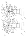
- the cheek plate 19 is penetrated by an opening rod 41 which is biased by a compression spring 42 in the direction of the pressing chamber 21 and axially movable.
- the opening rod 41 protrudes a piece over the jaw recess 20 into the baling chamber 21.
- At the lower end of the opening rod 41 is formed so that it projects into the downwardly tapered space between the two drive surfaces 24, 25 and fills it.
- the opening rod 41 When attaching the pressing device in the position shown in Figure 9 at a pipe joint, the opening rod 41 is moved through the pipe joint in the direction of the magnets 39, 40 and thereby spreads the drive lever 22, 23 a piece apart. The magnets 39, 40 are released, and the cheek plates 10, 11 move to the closed position. After removal of the pressing device 1 of the pipe joint, the opening rod 41 is pressed by the compression spring 42 back into the position shown in Figure 9.
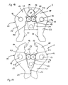
- Figures 10 and 11 show the pressing tool 3 after removal of the drive 2, wherein here the front bearing plate 9 is not shown. In this way, the view is released on two friction wheels 43, 44 which are freely rotatable in.der cheek plate 19 are mounted side by side and abut each other with their peripheral surfaces.
- the movable press jaws 10, 11 have transfer surfaces 45, 46, which are formed as circular arc sections which extend concentrically to the bearing pins 12, 13. They lie on the peripheral surfaces of the respective adjacent friction wheel 43, 44th at.
- the pressing tool 47 shown in Figures 12 and 13 is also shown without drive. It has two mirror-image forming cheek plates 48, 49, which are arranged between two bearing plates 50, of which the front bearing plate lying in the view - as in the previous embodiments - is omitted. On the bearing plates 50, the cheek plates 48, 49 are pivotally mounted on bearing pins 51, 52. can be connected via a further bearing pin 53 - similar to the embodiments of Figures 1 to 9 - a drive.
- the Preßbacken 48, 49 have above the bearing pin 51, 52 jaw arms 54, 55, in the opposite jaw recesses 56, 57 are formed. In contrast to the embodiments described so far, a third cheek plate is missing. Below the bearing pins 51, 52 run the Preßbakken 48, 49 in drive lever 58, 59, the opposite drive surfaces 60, 61 form. In the gap between the drive surfaces 60, 61 can - as in the embodiments described above - the drive stem of a drive motor are retracted.
- the Preßbacken 48, 49 have slightly below the plane of the bearing pin 51, 52 opposite, approximately semicircular recesses 62, 63, into which a transmission pin 64 is inserted circular cross-section. In the axial direction of the transmission pin 64 is bordered by the two bearing plates 50 so that it can not fall out.
- the recesses 62, 63 adjoin one another on the top side, while a free space 65 exists on the bottom side.
- the free space 65 is shaped so that a pivoting of the cheek plates 48, 49 from the closed position ( Figure 12) in the open position ( Figure 13) is possible.
Landscapes
- Engineering & Computer Science (AREA)
- Manufacturing & Machinery (AREA)
- Mechanical Engineering (AREA)
- Manipulator (AREA)
- Press Drives And Press Lines (AREA)
- Shaping Of Tube Ends By Bending Or Straightening (AREA)
- Hand Tools For Fitting Together And Separating, Or Other Hand Tools (AREA)
- Confectionery (AREA)
- Apparatuses For Bulk Treatment Of Fruits And Vegetables And Apparatuses For Preparing Feeds (AREA)
- Encapsulation Of And Coatings For Semiconductor Or Solid State Devices (AREA)
Claims (14)
- Appareil de pressage (1) pour assembler des pièces tubulaires (28), avec au moins deux mors de pressage (10, 11, 19, 48, 49) qui entourent un espace de pressage (21) et qui sont - ou parmi lesquels au moins deux sont - à mobilité relative de telle sorte qu'ils peuvent être déplacés dans une position ouverte pour la mise en place sur la pièce (28) et jusque dans une position fermée pour le processus d'assemblage par pressage au moyen d'un moteur d'entraînement (4), sachant que les ou au moins deux des mors de pressage mobiles (10, 11, 19, 48, 49) sont couplés de telle sorte que, lors de l'actionnement d'un mors de pressage (10, 11, 19, 48, 49), le ou les autres mors de pressage mobiles (10, 11, 19, 48, 49) sont également déplacés dans le même sens, et sachant que l'appareil de pressage (1) présente sur son boîtier une région de préhension pour une main (26) maintenant l'appareil, caractérisé en ce que la région de préhension est prévue de telle sorte qu'elle permet de maintenir et de manoeuvrer l'appareil de pressage (1) avec une main, restant au même endroit de la région de préhension, sachant qu'un des mors de pressage mobiles (10, 11, 19, 48, 49) peut, au moyen de la main de maintien (26) sur la région de préhension, être déplacé en direction de la position ouverte, et sachant que l'appareil de pressage (1) présente un commutateur (29) pour activer l'entraînement (4), qui est associé à la région de préhension de telle sorte qu'il peut être actionné par un doigt (27) ou par le pouce de la main de maintien (26).
- Appareil de pressage selon la revendication 1, caractérisé en ce que les ou au moins deux des mors de pressage mobiles (10, 11) sont respectivement mutuellement reliés par l'intermédiaire d'une tige d'accouplement (32).
- Appareil de pressage selon la revendication 1 ou 2, caractérisé en ce que les ou au moins deux des mors de pressage mobiles (10, 11) sont mutuellement reliés par l'intermédiaire d'un engagement par friction de couplage (43 à 46) ou par l'intermédiaire d'un engrènement de couplage.
- Appareil de pressage selon l'une des revendications 1 à 3, caractérisé en ce que les ou au moins deux des mors de pressage mobiles (48, 49) présentent deux évidements en vis-à-vis (62, 63) dans lesquels un élément de couplage (64) s'insère de telle sorte que, lors de l'actionnement de l'un (48, 49) des mors de pressage, l'autre mors de pressage (49, 49) est également déplacé dans le même sens.
- Appareil de pressage selon l'une des revendications 1 à 4, caractérisé en ce que les mors de pressage accouplés (10, 11, 19, 48, 49) sont sollicités par ressort dans la direction de fermeture.
- Appareil de pressage selon l'une des revendications 1 à 5, caractérisé en ce que les mors de pressage accouplés (10, 11, 19, 48, 49) présentent ou sont reliés à des leviers d'entraînement (22, 23, 58, 59) qui peuvent être sollicités par un entraînement (2) dans la direction de fermeture et qui se terminent au voisinage de la région de préhension.
- Appareil de pressage selon l'une des revendications 1 à 5, caractérisé en ce que l'appareil de pressage (1) présente une région de préhension pour saisir l'appareil de pressage (1) avec une main (26), et en ce qu'est associé à la région de préhension un levier d'actionnement (33) par l'intermédiaire duquel un des mors de pressage mobiles (10) peut être sollicité en direction de la position ouverte.
- Appareil de pressage selon l'une des revendications 1 à 7, caractérisé en ce qu'il est prévu un dispositif de blocage (35) pour bloquer à force et en engagement positif au moins un des mors de pressage accouplés (10, 11).
- Appareil de pressage selon la revendication 8, caractérisé en ce que le dispositif de blocage (35) est réalisé sous forme d'aimants (39, 40).
- Appareil de pressage selon la revendication 9, caractérisé en ce que les mors de pressage mobiles (10, 11) présentent des leviers d'entraînement (22, 23) qui sont pourvus des aimants (30, 40) de telle sorte que ces derniers s'appliquent l'un contre l'autre dans la position ouverte des mors de pressage (10, 11).
- Appareil de pressage selon la revendication 10, caractérisé en ce que le dispositif de blocage (35) est réalisé sous forme d'élément de blocage mobile (36), qui peut être déplacé dans une position de blocage dans la position ouverte des mors de pressage (10, 11).
- Appareil de pressage selon la revendication 11, caractérisé en ce que l'élément de blocage (36) est sollicité par ressort en direction de la position de blocage.
- Appareil de pressage selon la revendication 12, caractérisé en ce que l'appareil de pressage (1) présente une région de préhension pour saisir l'appareil de pressage (1) avec une main (26), et l'élément de blocage (36) est associé à la région de préhension de telle sorte que l'élément de blocage (36) peut être actionné par cette main (26).
- Appareil de pressage selon l'une des revendications 8 à 13, caractérisé en ce qu'un palpeur mobile (41) s'enfonce dans l'espace de pressage (21) et est couplé au dispositif de blocage (35, 39, 40) de telle sorte qu'il produit un déblocage de l'élément de blocage (35) lorsque l'appareil de pressage (1) est mis en place sur la pièce (28).
Applications Claiming Priority (2)
| Application Number | Priority Date | Filing Date | Title |
|---|---|---|---|
| DE29703053U | 1997-02-21 | ||
| DE29703053U DE29703053U1 (de) | 1997-02-21 | 1997-02-21 | Preßgerät |
Publications (3)
| Publication Number | Publication Date |
|---|---|
| EP0860245A2 EP0860245A2 (fr) | 1998-08-26 |
| EP0860245A3 EP0860245A3 (fr) | 2003-02-12 |
| EP0860245B1 true EP0860245B1 (fr) | 2006-04-19 |
Family
ID=8036291
Family Applications (1)
| Application Number | Title | Priority Date | Filing Date |
|---|---|---|---|
| EP19980101788 Expired - Lifetime EP0860245B1 (fr) | 1997-02-21 | 1998-02-03 | Dispositif de pressage |
Country Status (2)
| Country | Link |
|---|---|
| EP (1) | EP0860245B1 (fr) |
| DE (2) | DE29703053U1 (fr) |
Cited By (5)
| Publication number | Priority date | Publication date | Assignee | Title |
|---|---|---|---|---|
| DE102007007294B3 (de) * | 2007-02-14 | 2008-07-10 | Rothenberger Ag | Antriebsgerät mit einer Kupplung für Werkzeugköpfe |
| DE102007061164A1 (de) * | 2007-12-17 | 2009-06-18 | Viega Gmbh & Co. Kg | Presswerkzeug mit bistabilem Spannungsmechanismus |
| US10179398B2 (en) | 2011-05-09 | 2019-01-15 | Viega Technology Gmbh & Co. Kg | Jointing clamp and method for producing a compression joint |
| US11597064B2 (en) | 2018-08-23 | 2023-03-07 | Wezag Gmbh & Co. Kg | Pressing tongs or crimping pliers |
| US12611754B2 (en) | 2023-06-09 | 2026-04-28 | Black & Decker Inc. | Crimping and/or pinching accessory for power tool |
Families Citing this family (17)
| Publication number | Priority date | Publication date | Assignee | Title |
|---|---|---|---|---|
| DE10216213A1 (de) * | 2002-04-10 | 2003-10-23 | Klauke Gmbh Gustav | Elektrohydraulisches Verpressgerät und Verfahren zum Betreiben desselben |
| DE19925504B4 (de) * | 1999-03-02 | 2011-08-18 | Gustav Klauke GmbH, 42855 | System zum sicheren Aufbringen von Pressfittings, Presswerkzeug und Pressfitting |
| ES2202030T3 (es) * | 2000-01-07 | 2004-04-01 | Von Arx Ag | Pinza de prensado. |
| DE10101440B4 (de) * | 2001-01-15 | 2017-10-26 | REMS-WERK Christian Föll und Söhne GmbH & Co. | Preßzange |
| JP2005501731A (ja) | 2001-09-11 | 2005-01-20 | エマーソン エレクトリック カンパニー | 圧着アセンブリ |
| US7059166B2 (en) | 2002-06-17 | 2006-06-13 | Emerson Electric Co. | Method and apparatus for assuring or determining appropriate closure of a crimp assembly |
| CN100413624C (zh) * | 2003-03-06 | 2008-08-27 | 沃恩阿克斯公开股份有限公司 | 压制装置 |
| DE202006013693U1 (de) | 2006-09-07 | 2008-01-17 | Gustav Klauke Gmbh | Pressbackenpaar für hydraulische oder elektrische Verpressgeräte |
| US7216523B2 (en) | 2004-07-02 | 2007-05-15 | Gustav Klauke Gmbh | Pair of pressing jaws for hydraulic or electric pressing tools, and insulating covering for a pressing jaw |
| US7464578B2 (en) | 2005-06-03 | 2008-12-16 | Fci Americas Technology, Inc. | Hand-held, portable, battery-powered hydraulic tool |
| US8074485B2 (en) | 2008-07-08 | 2011-12-13 | Tyco Electronics Corporation | Tool head assemblies for pressing devices |
| US10226826B2 (en) | 2013-10-22 | 2019-03-12 | Milwaukee Electric Tool Corporation | Hydraulic power tool |
| DE102013112848B3 (de) | 2013-11-21 | 2015-04-23 | Viega Gmbh & Co. Kg | Presswerkzeug mit bistabilem Spannungsmechanismus |
| DE102014112869B3 (de) | 2014-09-08 | 2016-01-07 | Viega Gmbh & Co. Kg | Presswerkzeug mit zuschaltbarem bistabilen Spannmechanismus |
| CN205977914U (zh) | 2015-05-06 | 2017-02-22 | 米沃奇电动工具公司 | 液压动力工具 |
| US11641084B2 (en) | 2018-08-20 | 2023-05-02 | Hubbell Incorporated | Portable in-line dieless crimping tool |
| DE112022002592T5 (de) | 2021-06-21 | 2024-03-07 | Milwaukee Electric Tool Corporation | Systeme und verfahren zum auswerten von crimpanwendungen |
Family Cites Families (8)
| Publication number | Priority date | Publication date | Assignee | Title |
|---|---|---|---|---|
| DE2136782C2 (de) * | 1971-07-23 | 1982-12-02 | Novopress GmbH Pressen und Presswerkzeuge & Co KG, 4000 Düsseldorf | Tragbares druckmittelbetriebenes Klemmwerkzeug |
| JPS53130600A (en) * | 1977-04-19 | 1978-11-14 | Naokazu Ueda | Pinchers with magnetic spring |
| FR2528750B1 (fr) * | 1982-06-21 | 1987-01-16 | Bazantay Sarl Ets | Pince a sertir des viroles sur des canalisations, des cables ou des produits similaires |
| DE3423283A1 (de) * | 1984-06-23 | 1986-01-02 | Helmut Dipl.-Ing. 4040 Neuss Dischler | Klemmwerkzeug, insbesondere zum verbinden von rohren und anderen profilen |
| DE3713215A1 (de) * | 1987-04-18 | 1988-11-03 | Mag Maschinen Und Apparate Ges | Spannzange |
| DE3723330A1 (de) * | 1987-07-15 | 1989-01-26 | Paul Zahn | Hydraulisch betaetigtes handgeraet |
| DE4240427C1 (de) * | 1992-12-02 | 1994-01-20 | Novopress Gmbh | Preßwerkzeug |
| DE29502032U1 (de) * | 1995-02-08 | 1995-03-23 | Rems-Werk Christian Föll und Söhne GmbH & Co, 71332 Waiblingen | Preßwerkzeug |
-
1997
- 1997-02-21 DE DE29703053U patent/DE29703053U1/de not_active Expired - Lifetime
-
1998
- 1998-02-03 EP EP19980101788 patent/EP0860245B1/fr not_active Expired - Lifetime
- 1998-02-03 DE DE59813489T patent/DE59813489D1/de not_active Expired - Lifetime
Cited By (7)
| Publication number | Priority date | Publication date | Assignee | Title |
|---|---|---|---|---|
| DE102007007294B3 (de) * | 2007-02-14 | 2008-07-10 | Rothenberger Ag | Antriebsgerät mit einer Kupplung für Werkzeugköpfe |
| EP1958732A2 (fr) | 2007-02-14 | 2008-08-20 | Rothenberger AG | Appareil d'entraînement doté d'un embrayage pour têtes d'outil |
| DE102007061164A1 (de) * | 2007-12-17 | 2009-06-18 | Viega Gmbh & Co. Kg | Presswerkzeug mit bistabilem Spannungsmechanismus |
| DE102007061164B4 (de) * | 2007-12-17 | 2010-03-04 | Viega Gmbh & Co. Kg | Presswerkzeug mit bistabilem Spannungsmechanismus |
| US10179398B2 (en) | 2011-05-09 | 2019-01-15 | Viega Technology Gmbh & Co. Kg | Jointing clamp and method for producing a compression joint |
| US11597064B2 (en) | 2018-08-23 | 2023-03-07 | Wezag Gmbh & Co. Kg | Pressing tongs or crimping pliers |
| US12611754B2 (en) | 2023-06-09 | 2026-04-28 | Black & Decker Inc. | Crimping and/or pinching accessory for power tool |
Also Published As
| Publication number | Publication date |
|---|---|
| EP0860245A3 (fr) | 2003-02-12 |
| DE59813489D1 (de) | 2006-05-24 |
| DE29703053U1 (de) | 1997-04-10 |
| EP0860245A2 (fr) | 1998-08-26 |
Similar Documents
| Publication | Publication Date | Title |
|---|---|---|
| EP0860245B1 (fr) | Dispositif de pressage | |
| EP0451806B1 (fr) | Outil de pressage | |
| EP1223008B1 (fr) | Pince de sertissage | |
| DE4240427C1 (de) | Preßwerkzeug | |
| EP3614507B1 (fr) | Pinces à presser ou à sertir | |
| DE3423283C2 (fr) | ||
| DE112014003298T5 (de) | Spannvorrichtung | |
| EP2734316B1 (fr) | Presse manuelle | |
| DE19621877A1 (de) | Preßzange | |
| EP2233086A1 (fr) | Dispositif pour extraire les tiques | |
| DE3617529C2 (fr) | ||
| DE102009000153B3 (de) | Zange zur Herstellung einer Schiebehülsenverbindung | |
| DE4323669C2 (de) | Vorrichtung zum Herausziehen eines in einem Meißelhalter gehaltenen Meißels | |
| DE10243707B3 (de) | Handzange zum Verpressen von Rohrverbindungen | |
| DE29717314U1 (de) | Preßwerkzeug | |
| EP0631850A1 (fr) | Dispositif d'usinage | |
| DE10217266C5 (de) | Preßzange zum Verpressen von Hohlkörpern | |
| DE29517518U1 (de) | Preßwerkzeug | |
| EP3718695B1 (fr) | Outil de compression pour un raccord à manchon de compression | |
| WO1997030825A1 (fr) | Outil pour pressage de raccords de tuyaux | |
| DE1294300B (de) | Werkzeug zum axialen Hoch- oder Abziehen oder Zurueckdruecken von Ringen u. dgl. | |
| DE29916524U1 (de) | Nietsetzgerät | |
| DE20121845U1 (de) | Preßzange | |
| DE1809853B2 (de) | Vorrichtung zum aufpressen von huelsen od.dgl. auf draehte, seile, kabel od.dgl | |
| DE7703222U1 (de) | Vorrichtung zum aufweiten von aufgeschnittenen federnden ringen |
Legal Events
| Date | Code | Title | Description |
|---|---|---|---|
| PUAI | Public reference made under article 153(3) epc to a published international application that has entered the european phase |
Free format text: ORIGINAL CODE: 0009012 |
|
| AK | Designated contracting states |
Kind code of ref document: A2 Designated state(s): AT BE CH DE DK ES FI FR GB GR IE IT LI LU MC NL PT SE |
|
| AX | Request for extension of the european patent |
Free format text: AL;LT;LV;MK;RO;SI |
|
| RIC1 | Information provided on ipc code assigned before grant |
Free format text: 7B 25B 27/14 A, 7H 01R 43/042 B, 7B 25B 27/10 B |
|
| PUAL | Search report despatched |
Free format text: ORIGINAL CODE: 0009013 |
|
| 17P | Request for examination filed |
Effective date: 20021205 |
|
| AK | Designated contracting states |
Designated state(s): AT BE CH DE DK ES FI FR GB GR IE IT LI LU MC NL PT SE |
|
| AX | Request for extension of the european patent |
Extension state: AL LT LV MK RO SI |
|
| AKX | Designation fees paid |
Designated state(s): CH DE FR GB IT LI |
|
| 17Q | First examination report despatched |
Effective date: 20031001 |
|
| GRAP | Despatch of communication of intention to grant a patent |
Free format text: ORIGINAL CODE: EPIDOSNIGR1 |
|
| GRAS | Grant fee paid |
Free format text: ORIGINAL CODE: EPIDOSNIGR3 |
|
| GRAA | (expected) grant |
Free format text: ORIGINAL CODE: 0009210 |
|
| AK | Designated contracting states |
Kind code of ref document: B1 Designated state(s): CH DE FR GB IT LI |
|
| PG25 | Lapsed in a contracting state [announced via postgrant information from national office to epo] |
Ref country code: IT Free format text: LAPSE BECAUSE OF FAILURE TO SUBMIT A TRANSLATION OF THE DESCRIPTION OR TO PAY THE FEE WITHIN THE PRESCRIBED TIME-LIMIT;WARNING: LAPSES OF ITALIAN PATENTS WITH EFFECTIVE DATE BEFORE 2007 MAY HAVE OCCURRED AT ANY TIME BEFORE 2007. THE CORRECT EFFECTIVE DATE MAY BE DIFFERENT FROM THE ONE RECORDED. Effective date: 20060419 Ref country code: GB Free format text: LAPSE BECAUSE OF FAILURE TO SUBMIT A TRANSLATION OF THE DESCRIPTION OR TO PAY THE FEE WITHIN THE PRESCRIBED TIME-LIMIT Effective date: 20060419 |
|
| REG | Reference to a national code |
Ref country code: GB Ref legal event code: FG4D Free format text: NOT ENGLISH |
|
| REF | Corresponds to: |
Ref document number: 59813489 Country of ref document: DE Date of ref document: 20060524 Kind code of ref document: P |
|
| GBV | Gb: ep patent (uk) treated as always having been void in accordance with gb section 77(7)/1977 [no translation filed] |
Effective date: 20060419 |
|
| PLAX | Notice of opposition and request to file observation + time limit sent |
Free format text: ORIGINAL CODE: EPIDOSNOBS2 |
|
| PLBI | Opposition filed |
Free format text: ORIGINAL CODE: 0009260 |
|
| 26 | Opposition filed |
Opponent name: RIDGID Effective date: 20070110 |
|
| EN | Fr: translation not filed | ||
| PLAF | Information modified related to communication of a notice of opposition and request to file observations + time limit |
Free format text: ORIGINAL CODE: EPIDOSCOBS2 |
|
| PLAF | Information modified related to communication of a notice of opposition and request to file observations + time limit |
Free format text: ORIGINAL CODE: EPIDOSCOBS2 |
|
| PLAF | Information modified related to communication of a notice of opposition and request to file observations + time limit |
Free format text: ORIGINAL CODE: EPIDOSCOBS2 |
|
| PLBP | Opposition withdrawn |
Free format text: ORIGINAL CODE: 0009264 |
|
| PLBD | Termination of opposition procedure: decision despatched |
Free format text: ORIGINAL CODE: EPIDOSNOPC1 |
|
| PG25 | Lapsed in a contracting state [announced via postgrant information from national office to epo] |
Ref country code: FR Free format text: LAPSE BECAUSE OF FAILURE TO SUBMIT A TRANSLATION OF THE DESCRIPTION OR TO PAY THE FEE WITHIN THE PRESCRIBED TIME-LIMIT Effective date: 20070309 |
|
| PLAB | Opposition data, opponent's data or that of the opponent's representative modified |
Free format text: ORIGINAL CODE: 0009299OPPO |
|
| PLBM | Termination of opposition procedure: date of legal effect published |
Free format text: ORIGINAL CODE: 0009276 |
|
| STAA | Information on the status of an ep patent application or granted ep patent |
Free format text: STATUS: OPPOSITION PROCEDURE CLOSED |
|
| 27C | Opposition proceedings terminated |
Effective date: 20080410 |
|
| PG25 | Lapsed in a contracting state [announced via postgrant information from national office to epo] |
Ref country code: FR Free format text: LAPSE BECAUSE OF FAILURE TO SUBMIT A TRANSLATION OF THE DESCRIPTION OR TO PAY THE FEE WITHIN THE PRESCRIBED TIME-LIMIT Effective date: 20060419 |
|
| REG | Reference to a national code |
Ref country code: CH Ref legal event code: NV Representative=s name: ALDO ROEMPLER PATENTANWALT |
|
| PGFP | Annual fee paid to national office [announced via postgrant information from national office to epo] |
Ref country code: CH Payment date: 20170221 Year of fee payment: 20 Ref country code: DE Payment date: 20170302 Year of fee payment: 20 |
|
| REG | Reference to a national code |
Ref country code: DE Ref legal event code: R071 Ref document number: 59813489 Country of ref document: DE |
|
| REG | Reference to a national code |
Ref country code: CH Ref legal event code: PL |