EP0860246A2 - Dispositif pour guider et supporter une perçeuse à main - Google Patents
Dispositif pour guider et supporter une perçeuse à main Download PDFInfo
- Publication number
- EP0860246A2 EP0860246A2 EP98102168A EP98102168A EP0860246A2 EP 0860246 A2 EP0860246 A2 EP 0860246A2 EP 98102168 A EP98102168 A EP 98102168A EP 98102168 A EP98102168 A EP 98102168A EP 0860246 A2 EP0860246 A2 EP 0860246A2
- Authority
- EP
- European Patent Office
- Prior art keywords
- handle
- receiving body
- receiving
- holder
- hand drill
- Prior art date
- Legal status (The legal status is an assumption and is not a legal conclusion. Google has not performed a legal analysis and makes no representation as to the accuracy of the status listed.)
- Withdrawn
Links
Images
Classifications
-
- B—PERFORMING OPERATIONS; TRANSPORTING
- B25—HAND TOOLS; PORTABLE POWER-DRIVEN TOOLS; MANIPULATORS
- B25H—WORKSHOP EQUIPMENT, e.g. FOR MARKING-OUT WORK; STORAGE MEANS FOR WORKSHOPS
- B25H1/00—Work benches; Portable stands or supports for positioning portable tools or work to be operated on thereby
- B25H1/0021—Stands, supports or guiding devices for positioning portable tools or for securing them to the work
- B25H1/0042—Stands
-
- B—PERFORMING OPERATIONS; TRANSPORTING
- B25—HAND TOOLS; PORTABLE POWER-DRIVEN TOOLS; MANIPULATORS
- B25F—COMBINATION OR MULTI-PURPOSE TOOLS NOT OTHERWISE PROVIDED FOR; DETAILS OR COMPONENTS OF PORTABLE POWER-DRIVEN TOOLS NOT PARTICULARLY RELATED TO THE OPERATIONS PERFORMED AND NOT OTHERWISE PROVIDED FOR
- B25F5/00—Details or components of portable power-driven tools not particularly related to the operations performed and not otherwise provided for
- B25F5/02—Construction of casings, bodies or handles
- B25F5/025—Construction of casings, bodies or handles with torque reaction bars for rotary tools
- B25F5/026—Construction of casings, bodies or handles with torque reaction bars for rotary tools in the form of an auxiliary handle
Definitions
- the invention relates to a device for guiding and holding a one having a cylindrical receiving shaft Drive unit, especially a hand drill, consisting of an annular to the receiving shaft clamping body and a handle.
- a hand drill With hand drills, the most varied of operations such as grinding, brushing, polishing, roughening, Structuring, rust removal, deburring, removing paint and the like. To do this, the drills with a wide variety of processing tools. In Depending on the individual processing operations, the Hand drill guided with the processing tool by hand or fixed in place. For good leadership, keeping and Moving a hand drill by hand is a device known, which consists of an annular receiving body, which has a radially extending slot on its circumference. This makes it possible to mount the cylindrical shaft insert the hand drill into the holder body and tighten. Closes on the receiving body a handle piece integrally connected to it.
- brackets known on the one hand on a base or the like by means of suitable Clamping devices can be secured. Furthermore point these brackets also have an annular receiving body on, which has a radial slot on its circumference and that after inserting the receiving shaft of the Hand drill can be tightened around the same.
- annular receiving body on, which has a radial slot on its circumference and that after inserting the receiving shaft of the Hand drill can be tightened around the same.
- both in the handle device and screws are mainly used for the bracket.
- the invention is therefore based on the object of a device for guiding and holding a cylindrical one
- a device for guiding and holding a cylindrical one To design the hand-held drill having the shank, that with the same moving guidance and holding and a stationary holding of a hand drill without large Effort is possible.
- the device should be designed in this way be that, if necessary, the bracket for a stationary Hold in the short term and without much effort and in particular removed and replaced without additional tools can be.
- Such a configuration makes it possible to use the hand drill either only with the handle or together to use with the bracket.
- the receiving body can unless it can be removed for other reasons must always be on the cylindrical shank of the hand drill remain.
- the changeover time is extremely short. Special Tools are not required for this.
- the storage The hand drill can either use the handle or done together with the bracket.
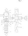
- a guide and hold device one having a cylindrical receiving shaft Hand drill shown, which consists of a receiving body 1, a handle 2 and a bracket 3. These three Parts in the drawing are not assembled shown.
- the receiving body 1 can in itself known, cylindrical shank of a hand drill be attached and clamped to the same.
- the receiving body 1 can be used for one purpose have known, radially extending slot and have a screw that clamps the allows inserted in the opening 4 receiving shaft.
- the receiving body however, from a bridge-like base body 5, the has a recess 6 perpendicular to the drawing.
- a clamping piece 7 is inserted.
- the of the clamping piece 7 and the base body 5 limited receiving opening 4 is now slightly larger than the diameter of the cylindrical shank of the hand drill.
- the clamping piece 7 has on its protruding into the base body 6 End a threaded hole 8, one for improvement screwed in the clarity not shown screw can be.
- the clamping piece can now be attached using this screw 7 pulled into the base body 6 and thus the receiving shaft the hand drill can be clamped.
- the receiving body 1 or the base body 5 has one approximately circular connection surface 9 on which one Connecting surface 10 of the handle 2 can be brought to bear is.
- This handle 2 now has a stepped bore 11 for receiving the aforementioned, but not shown Screw on.
- By turning the handle 2 with the screw used can now the receiving body 1 on the one hand be firmly connected to the handle 2.
- Such a configuration gives the possibility of the hand drill additionally to guide and hold over the handle 2.
- connection surfaces are 9, 10 of the receiving body 5 and handle 2 drawn at a distance from each other.
- the connection surfaces 9, 10 is now the end 12 of a Leg 13 of the bracket 3.
- This end 12 of the leg 13 is now designed so that it is between the connecting surfaces 9, 10 of receiving body 1 and handle 2 can be clamped.
- it has a slot 14 that is slightly wider than the outer diameter of the not shown Screw is. With this slot 14, the leg can now 13 of the bracket 3 pushed around the screw and thus at Contraction of the receiving body 1 and handle 2 between the connecting surface are clamped.
- the other leg 17 of the holder 3 on a board 18 or the like attached can be fixed or rotatable a screw clamp 19 may be connected.
- the bracket 3 is now in a very short time between the receiving body 1 and the handle 2 can be clamped and again removable. This allows the most diverse Machining operations are carried out with the hand drill.
Landscapes
- Engineering & Computer Science (AREA)
- Mechanical Engineering (AREA)
- Drilling And Boring (AREA)
- Gripping On Spindles (AREA)
Applications Claiming Priority (2)
| Application Number | Priority Date | Filing Date | Title |
|---|---|---|---|
| DE19706465 | 1997-02-19 | ||
| DE1997106465 DE19706465A1 (de) | 1997-02-19 | 1997-02-19 | Vorrichtung zum Führen und Halten einer Handbohrmaschine |
Publications (2)
| Publication Number | Publication Date |
|---|---|
| EP0860246A2 true EP0860246A2 (fr) | 1998-08-26 |
| EP0860246A3 EP0860246A3 (fr) | 1999-12-29 |
Family
ID=7820779
Family Applications (1)
| Application Number | Title | Priority Date | Filing Date |
|---|---|---|---|
| EP98102168A Withdrawn EP0860246A3 (fr) | 1997-02-19 | 1998-02-07 | Dispositif pour guider et supporter une perçeuse à main |
Country Status (2)
| Country | Link |
|---|---|
| EP (1) | EP0860246A3 (fr) |
| DE (1) | DE19706465A1 (fr) |
Family Cites Families (4)
| Publication number | Priority date | Publication date | Assignee | Title |
|---|---|---|---|---|
| DE2821132C2 (de) * | 1978-05-13 | 1982-12-30 | Robert 5446 Engeln Wolff | Aufspannvorrichtung für eine Handbohrmaschine |
| DE3619632A1 (de) * | 1986-06-11 | 1987-12-17 | Robert Wolff | Aufspannvorrichtung fuer eine antriebsmaschine, z.b. eine handbohrmaschine |
| DE3826212A1 (de) * | 1988-08-02 | 1990-02-08 | Bosch Gmbh Robert | Elektrisches handwerkzeug |
| DE3928541A1 (de) * | 1988-08-29 | 1990-03-01 | Walter Schweikert | Halterung fuer eine elektrische handwerkzeugmaschine |
-
1997
- 1997-02-19 DE DE1997106465 patent/DE19706465A1/de not_active Withdrawn
-
1998
- 1998-02-07 EP EP98102168A patent/EP0860246A3/fr not_active Withdrawn
Also Published As
| Publication number | Publication date |
|---|---|
| EP0860246A3 (fr) | 1999-12-29 |
| DE19706465A1 (de) | 1998-08-20 |
Similar Documents
| Publication | Publication Date | Title |
|---|---|---|
| DE602004004027T2 (de) | Haltevorrichtung für ein kraftbetriebenes Handwerkzeug, mit einem verstellbaren Wagen mit Behälter | |
| DE10020781B4 (de) | Abnehmbares Führungsanbringungsgerät | |
| EP0097294A1 (fr) | Etabli pour travaux avec serre-joint amovible | |
| DE4032176A1 (de) | Lochsaege | |
| EP3517249B1 (fr) | Dispositif de maintien pour une machine-outil portative | |
| DE602004007591T2 (de) | Führungseinheit für Handwerkszeugmaschine | |
| DE3829801C2 (de) | Zusatzhandgriff für motorisch betriebene Handwerkzeugmaschinen | |
| DE102018119980A1 (de) | Spann- oder Greifeinrichtung | |
| DE69921228T2 (de) | Einspannvorrichtung zum Schleifen von scharfkantigen Werkzeugen | |
| WO2008043514A1 (fr) | Manchon coulissant à monter sur la tige d'un outil à tournevis | |
| DE8320384U1 (de) | Vorrichtung für den Antrieb eines schwingbaren Werkzeuges | |
| DE102007057640B3 (de) | Werkzeugspanneinrichtung und Werkzeughalter | |
| EP0860246A2 (fr) | Dispositif pour guider et supporter une perçeuse à main | |
| DE4419668C1 (de) | Fräswerkzeug | |
| DE1427027A1 (de) | Verbindungsstueck zwecks Verbindung von einen Kraftantrieb aufweisenden Bohrmaschinen mit keinen Kraftantrieb aufweisenden Werkzeugen | |
| DE102006061757A1 (de) | Abtriebsteil an einer Handwerkzeugmaschine | |
| DE2513319C3 (de) | Spannvorrichtung mit zugehöriger Schraubzwinge | |
| DE29909645U1 (de) | Schraubverbindung, insbesondere zum Befestigen des Schwerts einer Kettensäge | |
| DE102004001148B3 (de) | Werkzeugaufnahmevorrichtung | |
| EP0765706A1 (fr) | Machine-outil portable | |
| EP2045041B1 (fr) | Dispositif de manipulation pour un support d'outil doté d'un dispositif de guidage | |
| DE1502979C (de) | Feilgerät | |
| DE860179C (de) | Einspannvorrichtung mit einer in einem Rahmen drehbar gelagerten Schraubenspindel | |
| DE3517141A1 (de) | Einheit zum festspannen von werkstuecken | |
| DE882506C (de) | Auswechselbarer Werkzeughalter |
Legal Events
| Date | Code | Title | Description |
|---|---|---|---|
| PUAI | Public reference made under article 153(3) epc to a published international application that has entered the european phase |
Free format text: ORIGINAL CODE: 0009012 |
|
| AK | Designated contracting states |
Kind code of ref document: A2 Designated state(s): AT BE DE DK ES FR GB IT NL SE |
|
| AX | Request for extension of the european patent |
Free format text: AL;LT;LV;MK;RO;SI |
|
| PUAL | Search report despatched |
Free format text: ORIGINAL CODE: 0009013 |
|
| AK | Designated contracting states |
Kind code of ref document: A3 Designated state(s): AT BE CH DE DK ES FI FR GB GR IE IT LI LU MC NL PT SE |
|
| AX | Request for extension of the european patent |
Free format text: AL;LT;LV;MK;RO;SI |
|
| RIC1 | Information provided on ipc code assigned before grant |
Free format text: 6B 25F 5/02 A, 6B 25H 1/00 B |
|
| AKX | Designation fees paid |
Free format text: AT BE DE DK ES FR GB IT NL SE |
|
| STAA | Information on the status of an ep patent application or granted ep patent |
Free format text: STATUS: THE APPLICATION IS DEEMED TO BE WITHDRAWN |
|
| 18D | Application deemed to be withdrawn |
Effective date: 20000630 |