EP0860321B1 - Feu de véhicule avec un dispositif de fixation - Google Patents
Feu de véhicule avec un dispositif de fixation Download PDFInfo
- Publication number
- EP0860321B1 EP0860321B1 EP98102957A EP98102957A EP0860321B1 EP 0860321 B1 EP0860321 B1 EP 0860321B1 EP 98102957 A EP98102957 A EP 98102957A EP 98102957 A EP98102957 A EP 98102957A EP 0860321 B1 EP0860321 B1 EP 0860321B1
- Authority
- EP
- European Patent Office
- Prior art keywords
- fixing
- locking element
- fixing projection
- vehicle
- aperture
- Prior art date
- Legal status (The legal status is an assumption and is not a legal conclusion. Google has not performed a legal analysis and makes no representation as to the accuracy of the status listed.)
- Expired - Lifetime
Links
- 238000003780 insertion Methods 0.000 claims description 39
- 230000037431 insertion Effects 0.000 claims description 39
- 230000001154 acute effect Effects 0.000 claims description 2
- 238000006073 displacement reaction Methods 0.000 claims 2
- 238000013459 approach Methods 0.000 description 33
- 230000002093 peripheral effect Effects 0.000 description 2
- 230000032683 aging Effects 0.000 description 1
- 230000018109 developmental process Effects 0.000 description 1
- 230000000694 effects Effects 0.000 description 1
- 238000009434 installation Methods 0.000 description 1
- 239000000463 material Substances 0.000 description 1
- 230000013011 mating Effects 0.000 description 1
Images


Classifications
-
- B—PERFORMING OPERATIONS; TRANSPORTING
- B60—VEHICLES IN GENERAL
- B60Q—ARRANGEMENT OF SIGNALLING OR LIGHTING DEVICES, THE MOUNTING OR SUPPORTING THEREOF OR CIRCUITS THEREFOR, FOR VEHICLES IN GENERAL
- B60Q1/00—Arrangement of optical signalling or lighting devices, the mounting or supporting thereof or circuits therefor
- B60Q1/02—Arrangement of optical signalling or lighting devices, the mounting or supporting thereof or circuits therefor the devices being primarily intended to illuminate the way ahead or to illuminate other areas of way or environments
- B60Q1/04—Arrangement of optical signalling or lighting devices, the mounting or supporting thereof or circuits therefor the devices being primarily intended to illuminate the way ahead or to illuminate other areas of way or environments the devices being headlights
- B60Q1/0408—Arrangement of optical signalling or lighting devices, the mounting or supporting thereof or circuits therefor the devices being primarily intended to illuminate the way ahead or to illuminate other areas of way or environments the devices being headlights built into the vehicle body, e.g. details concerning the mounting of the headlamps on the vehicle body
- B60Q1/0441—Arrangement of optical signalling or lighting devices, the mounting or supporting thereof or circuits therefor the devices being primarily intended to illuminate the way ahead or to illuminate other areas of way or environments the devices being headlights built into the vehicle body, e.g. details concerning the mounting of the headlamps on the vehicle body the housing being fastened onto the vehicle body using means other than screws
-
- B—PERFORMING OPERATIONS; TRANSPORTING
- B60—VEHICLES IN GENERAL
- B60Q—ARRANGEMENT OF SIGNALLING OR LIGHTING DEVICES, THE MOUNTING OR SUPPORTING THEREOF OR CIRCUITS THEREFOR, FOR VEHICLES IN GENERAL
- B60Q1/00—Arrangement of optical signalling or lighting devices, the mounting or supporting thereof or circuits therefor
- B60Q1/26—Arrangement of optical signalling or lighting devices, the mounting or supporting thereof or circuits therefor the devices being primarily intended to indicate the vehicle, or parts thereof, or to give signals, to other traffic
Definitions
- the invention relates to a lamp with a fastening device for vehicles, especially rear light for vehicles with the features according to the preamble of claim 1.
- a lamp with a fastening device for vehicles is from the German utility model 74 07 139 became known.
- the lamp shows made of plastic on the back of a bowl-shaped Forms reflector of the lamp and its front by a translucent Lens is completed.
- the reflector has a peak Opening for receiving a lamp.
- the lamp is in an opening of the Vehicle used and lies with a spring element, which an the opening seal surrounding the vehicle is at the edge of the opening of the vehicle on.
- the attachment lugs have a detent at the free end and are approximately springy in their entire length.
- the locking elements are in Fastening openings of the vehicle inserted and reach behind with her Detent automatically an edge area of the mounting opening. That from the circumferential seal formed spring element is compressed.
- the Resilient attachment approaches are transverse to their direction of insertion Lines movable in an elastic range and lying adjacent to the Latch under tension on the edge area of the fastening opening of the Vehicle. Because of this permanent spring force, the elasticity of the Attachment approaches with time and between attachment openings existing locking connection of the vehicle and the fastening approaches solve themselves automatically while driving. In addition, the locking connection can automatically change the lamp.
- a luminaire with a fastening device for vehicles according to the preamble of claim 1 has become known, which has three fastening lugs molded onto the back of the luminaire.
- Two of the fastening approaches each consist of two resilient tabs, one of the tabs being a locking element.
- the third fastening attachment has a resilient latching element at its free end, which is U-shaped.
- the legs of the U-shaped locking element are resilient and inserted in their entire length through the fastening opening.
- the resilient legs or the resilient tabs of the fastening lugs can be moved in an elastically flexible region at least about a line running transversely to the plugging direction of the lamp.
- the light adjoins the edge region of the fastening openings of the vehicle with the contact surfaces of the fastening projections directed in the plugging direction.
- the fastening openings of the vehicle must be made so large that the resilient latching elements can laterally deflect when they are passed through the fastening openings until they latch.
- the locking device In order to achieve a secure tight fit of the locking device, the locking device would have to be coupled to a locking device which holds the locking elements in their locked position.
- a locking device makes the lamp more expensive and the installation of the lamp is time-consuming and cumbersome.
- the locking elements In order to obtain a locking connection between them and the vehicle that is as secure as possible, the locking elements must rest resiliently transversely to the plugging direction on the edge region of the fastening opening of the vehicle. By aging the material of the resilient locking elements, the resilient properties of the locking elements can deteriorate.
- the fastening attachment provided at the free end with the U-shaped resilient latching element is designed to be flexible between the fastening openings of the vehicle and the rear of the lamp by at least one line running transversely to the direction of insertion in order to compensate for tolerances between the fastening approaches and the fastening openings of the vehicle. Despite this flexibility of the fastening approach, there remains a possible loosening of the locking connections.
- the object of the invention is that described in the preamble of claim 1 Fastening device of a lamp for vehicles so that the self-locking connection between the mounting attachment of the lamp and the Vehicle even in the opposite of the direction of insertion of the fastening approach acting large force, which can occur when changing the lamp, is secure against automatic loosening and also the fastening attachment transverse to its direction of insertion not under tension on an edge area of the Attachment opening must be present to keep the lamp on the vehicle.
- This object is achieved according to the invention by the feature of the characterizing part of the claim. As a result, the resilient locking element is only when plugged into the Fastening opening of the vehicle under tension on an edge area of the Mounting opening.
- the locking element can be opposite to the direction of insertion with a large force on the edge area of the mounting hole of the vehicle because the resilient locking element around a line running in the direction of insertion is movable.
- the attachment lug can have large holding forces that ensure the secure holding of the Lights on the vehicle are necessary to record when it is together with its insertable through the mounting hole of the vehicle End section is rigid.
- a captive engagement of the mounting approach in the mounting opening of the Vehicle also exists in the case of rough tolerances between lamp and vehicle, if the fastening projection at least one in the spring direction of the locking element has directed support surface with which the attachment approach to automatic intervention in the first edge region of the fastening opening a second edge area facing the first edge area Fastening opening slides along.
- This is a release of the self-locking Connection between the mounting bracket and the vehicle only possible if the locking element so far around the line extending in the direction of insertion elastic region is pressed until the locking element through the Fastening opening can be pulled through.
- the attachment approach is in his Particularly secure insertion direction in the vehicle's mounting opening can be locked if it is at least one in each on opposite sides Spring direction of the locking element has directed support surface.
- the attachment approach is particularly stable if at least one Support surface from an end face of one in the direction of insertion of the fastening projection extending stiffening rib is formed.
- the attachment approach is easy Thread into the mounting hole and the snap connection is easy Mating force can be produced if the resilient locking element is from a wall section is formed, which runs in and against the direction of insertion Has edge section, of which the first directed against the insertion direction Edge section automatically engages behind the fastening opening and the in Direction of insertion directed second edge section serves as a run-up slope with which the locking element when inserting the fastening approach on a first Edge area of the mounting opening slides until the locking element engages behind the first edge area of the fastening opening in a self-locking manner.
- the locking element with its main extent in one point Angle to the support surface of the attachment approach.
- the lamp is in the direction of insertion of the mounting bracket on the vehicle locked when an edge section of the Locking element limits a slot made in the fastening projection, which is transverse to the direction of insertion. This one reaches into this slot Locking element automatically gripped edge area of the mounting opening of the Vehicle.
- the resilient locking element can with a large force against the direction of insertion rest on the edge region of the fastening opening of the vehicle without due to high notch effect, the locking element from the free end portion of the Attachment approach can break off if a Eye-shaped opening is introduced, which to the resilient locking element is adjacent and open to the slot. It is also useful here if the attachment approach with in around the eye-shaped opening extending section is made thicker in its wall thickness.
- the lamp is rattle-free in the direction of insertion of the fastening attachment Vehicle can be held if the contact surface against the vehicle is from a spring element attached to the back of the lamp is formed by which is the first edge section of the Latching element against the automatically gripped first edge area of the Fastening opening is pressed.
- a seal can serve as a spring element, which lies tightly against an edge region of an opening of the vehicle through which a change of lamps of the lamp is possible.
- the lamp is with a large force in the direction of insertion against the force of the Spring element movable when in through the mounting hole at least one undercut can be introduced through the end section, which serves for the engagement of an auxiliary tool through which the fastening approach against the spring force of the spring element in a with the mounting opening locked end position can be brought.
- the lamp is also with large vertical forces occurring during driving Can be securely attached to the vehicle if there are several on the back of the lamp Attachment approaches are formed, of which at least two with their Support surfaces lie in intersecting surfaces.
- the Fastening opening of the vehicle insertable end portion of the Attachment approach integrally formed at least two of the resilient locking elements.
- the resilient locking elements should extend to a plug-in direction
- the central plane should be symmetrical so that it can be plugged in Forces acting as locking elements, almost eliminating torques arise and thus the attachment approach only by forces running in the direction of insertion is burdened.
- Figures 1, 2 and 3 show a rear light for vehicles with one off Plastic existing housing (27), the front by a translucent lens (28) is sealed.
- the back of the The housing (27) itself forms several reflectors (29) in their apex area several openings (30) serve to accommodate lamps, not shown.
- the Reflectors are formed by a collar (31) molded onto the back of the lamp surround.
- the collar (31) is interposed by a spring element (23), which is a seal, on a peripheral edge of an opening of the Vehicle (4). There is a change through the opening of the vehicle (4) the lamps of the lamp possible.
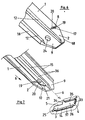
- the attachment lugs (1) are together with a free end section (9) rigid and are with the end section (9) through a fastening opening (3) of a vehicle (4) can be passed through.
- Staring at that End section (9) is formed on the side of a resilient locking element (2), which around a line (10) in the plugging direction (6) of the fastening projection (1) in an elastically resilient area is movable.
- the locking element (2) can also by several lines (10) which run from an elastic section of the Fastening approach are formed, be movable.
- the locking element (2) runs with its main extension at an acute angle (a) to the main extension of the End section (9) of the fastening projection (1).
- the locking element (2) has against the direction of insertion (6) at right angles to the direction of insertion (6) extending first edge section (17), which self-locking the first Edge area (5) of the fastening opening (3) engages behind.
- the locking element (2) is in seen in its spring direction (11) triangular, the sides of the Triangle from the line (10), the first edge portion (17) and a second Edge section (18) are formed.
- the second edge section (18) and an oblique running fourth edge section (32) of the end section (9) taper the Attachment projection (1) towards its free end.
- the second and fourth Edge section (18, 32) serve as run-up slope, through which the Attachment attachment (1) easily into the attachment opening (3) of the vehicle (4) is threadable.
- the first edge section (17) of the resilient locking element (2) and third edge section (22) of the attachment projection (1) delimit one in the Fastening projection (1) introduced slot (19), in which the edge area (5) the fastening opening (3) engages with the fastening attachment (1) locked in place.
- Attachment approach (1) is an eye-shaped opening (20) which leads to Slot (19) is open.
- the mounting hole (3) of the vehicle (4) is rectangular in shape and points to the edge area (5) opposite side on the edge area (14) on which the Fastening attachment (1) in its locked position with two support surfaces (12) runs adjacent.
- the support surfaces (12) are of stiffening ribs (16) formed, which extend in the plug-in direction (6) of the fastening projection (1).
- the fastening projection (1) is transverse to the spring (11) and the direction of insertion (6) can be locked in the fastening opening (3).
- the one on the Area (26) adjoining area (25) of the fastening opening (3) through which the locking element (2) can be passed through is narrower than the area (26).
- the fastening projection (1) borders with the side that the support surfaces (12) faces away from the first edge region (5) of the fastening opening (3).
- the rigid end section (9) has an undercut (24) which is by an hole formed in the end portion (9).
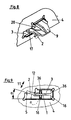
- the attachment lug (1) and the attachment opening (3) which in the figures 7 to 9 are shown, compared to that shown in FIGS. 4 to 6 Attachment approach (1) and the attachment opening (3) following differences.
- the eye-shaped opening (20) is circular and in the rigid part of the Fastening approach (1) introduced.
- the eye-shaped opening is from one Surround section (21), in which the fastening projection (1) in its Wall thickness is thicker.
- the support surface (15) of the fastening approach (1) which faces away from the edge region (14) of the fastening opening (3), adjoins a fifth edge region (35) of the fastening opening (3).
- Support surfaces (15) serve end faces of stiffening ribs (36), which in Plug direction (6) run.
- the narrow area (25) of the Fastening opening (3) is through an inwardly projecting section of the Vehicle (4) formed and has the first edge region (5), which the Reaches automatically behind locking element (2).
- the second, third and fifth border area (14, 33, 35) has an edge (37) angled in the direction of insertion (6).
- Retaining lugs (38) formed, which are conical towards their free end rejuvenate.
- the holding lugs (38) engage in holding openings (39) in the vehicle (4) and are locked in the holding openings (39) radially to the insertion direction (6).
- the Holding approaches (38) are only partially on the edge of the holding openings (39) of the Vehicle (4) so that it can be inserted into the holding openings (39) with little force are.
- the retaining lugs (38) can be made so long that they Fix the lamp opposite the vehicle (4) before the attachment lugs (1) engage the mounting hole (3) of the vehicle (4).
- With a big one Luminaire can also be formed more than two retaining lugs (38) to form a part absorb the large vertical forces occurring during driving.
Landscapes
- Engineering & Computer Science (AREA)
- Mechanical Engineering (AREA)
- Lighting Device Outwards From Vehicle And Optical Signal (AREA)
- Non-Portable Lighting Devices Or Systems Thereof (AREA)
Claims (15)
- Feu avec un dispositif de fixation pour véhicules, en particulier feu arrière pour véhicules, comportant au moins un talon de fixation (1) ménagé sur la face postérieure du feu, qui présente à son extrémité libre un élément d'enclenchement (2) qui est déplaçable dans une zone élastiquement flexible au moins autour d'une ligne (10) et avec lequel le talon de fixation (1) peut être enfiché dans une ouverture de fixation (3) du véhicule (4) et peut être immobilisé par autoenclenchement sur une zone de bord (5) de l'ouverture de fixation (3), et comportant au moins une surface d'appui (7) du feu orientée en direction d'enfichage (6) du talon de fixation (1) et susceptible d'être mise en appui sur le véhicule (4), l'élément d'enclenchement (2) étant moulé sur un tronçon d'extrémité (9), enfichable à travers l'ouverture de fixation (3) du véhicule (4), du talon de fixation (1), caractérisé en ce que ladite au moins une ligne (10) autour de laquelle l'élément d'enclenchement (2) est déplaçable dans une zone élastiquement flexible par rapport au tronçon d'extrémité (9) du talon de fixation (1) s'étend en direction d'enfichage (6) du talon de fixation (1).
- Feu selon la revendication 1, caractérisé en ce que le talon de fixation (1) est réalisé rigide conjointement avec son tronçon d'extrémité (9) enfichable à travers l'ouverture de fixation (3) du véhicule (4).
- Feu selon l'une ou l'autre des revendications 1 et 2, caractérisé en ce que le talon de fixation (1) présente au moins une surface de soutien (12) orientée en direction d'élasticité (11) de l'élément d'enclenchement (2), avec laquelle le talon de fixation (1) glisse sur une deuxième zone de bord (14) de l'ouverture de fixation (3), tournée vers la première zone de bord (5) jusqu'à venir s'engager automatiquement dans la première zone de bord (5) de l'ouverture de fixation (3).
- Feu selon l'une des revendications 1 à 3, caractérisé en ce que l'élément d'enclenchement (2) s'étend avec son extension principale sous un angle aigu (a) par rapport à la surface de soutien (12) du talon de fixation (1).
- Feu selon l'une des revendications 1 à 4, caractérisé en ce que le talon de fixation (1) présente sur des côtés détournés l'un de l'autre au moins une surface de soutien respective (12, 15) orientée en direction d'élasticité (11) de l'élément d'enclenchement (2).
- Feu selon l'une des revendications 3 à 5, caractérisé en ce qu'au moins une surface de soutien respective (12, 15) est formée par une surface frontale d'une nervure de renforcement (16) s'étendant en direction d'enfichage (6) du talon de fixation (1).
- Feu selon l'une des revendications 1 à 6, caractérisé en ce que l'élément d'enclenchement (2) élastique est formé par un tronçon de paroi qui présente un tronçon de bord (18) s'étendant dans la direction d'enfichage et un tronçon de bord (17) s'étendant à l'opposé de la direction d'enfichage (6), dont le premier tronçon de bord (17) orienté à l'opposé de la direction d'enfichage (6) saisit automatiquement par l'arrière l'ouverture de fixation (3) et le deuxième tronçon de bord (18) orienté en direction d'enfichage (6) sert de pente d'accès avec laquelle l'élément d'enclenchement (2) glisse le long d'une première zone de bord (13) de l'ouverture de fixation (3) lors de l'enfichage du talon de fixation (1) jusqu'à ce que l'élément d'enclenchement (2) saisisse automatiquement par l'arrière la première zone de bord (5) de l'ouverture de fixation (3).
- Feu selon l'une des revendications 1 à 7, caractérisé en ce qu'un tronçon de bord (17), dirigé à l'opposé de la direction d'enfichage (6), de l'élément d'enclenchement (2), délimite une fente (19) ménagée dans le talon de fixation (1), laquelle s'étend perpendiculairement à la direction d'enfichage (6).
- Feu selon la revendication 8, caractérisé en ce que dans le talon de fixation (1) est ménagée une ouverture (20) en forme d'oeillet qui est adjacente à l'élément d'enclenchement (2) élastique et qui est ouverte vers la fente (19).
- Feu selon la revendication 9, caractérisé en ce que le talon de fixation (1) est réalisé avec une paroi plus épaisse dans un tronçon (21) s'étendant autour de l'ouverture (20) en forme d'oeillet.
- Feu selon l'une des revendications 7 à 10, caractérisé en ce que la surface d'appui (7) du feu qui peut être appliquée contre le véhicule (4) est formée par un élément ressort (23) monté sur la face postérieure du feu, par lequel le premier tronçon de bord (17), orienté à l'opposé de la direction d'enfichage (6), de l'élément d'enclenchement (2), est pressé contre la première zone de bord (5) automatiquement saisie par l'arrière, de l'ouverture de fixation (3).
- Feu selon l'une des revendications 1 à 11, caractérisé en ce que dans le tronçon d'extrémité (9) que l'on peut faire passer à travers l'ouverture de fixation (3) est ménagée au moins une contre-dépouille (24) qui sert à l'engagement d'un outil auxiliaire par lequel le talon de fixation (1) peut être amené à l'encontre de la force élastique de l'élément ressort (23) jusque dans une position finale enclenchée avec l'ouverture de fixation (3).
- Feu selon l'une des revendications 3 à 12, caractérisé en ce que les surfaces de soutien (12) d'au moins deux talons de fixation (1) sont situées dans des surfaces (13) qui se recoupent.
- Feu selon l'une des revendications 1 à 13, caractérisé en ce que l'ouverture de fixation (3) dans le véhicule est réalisée rectangulaire, et une région (26) de l'ouverture de fixation (3) rectangulaire, dans laquelle on peut enficher le tronçon d'extrémité (9) du talon de fixation (1) présentant la surface de soutien (12), est réalisée plus large que la région (25) à travers laquelle on peut faire passer l'élément d'enclenchement (2) élastique.
- Feu selon l'une des revendications 1 à 14, caractérisé en ce qu'au moins deux des éléments d'enclenchement (2) élastiques sont moulés sur le tronçon d'extrémité (9) du talon de fixation (1), que l'on peut enficher à travers l'ouverture de fixation (3) du véhicule (4).
Applications Claiming Priority (2)
| Application Number | Priority Date | Filing Date | Title |
|---|---|---|---|
| DE19707094A DE19707094C1 (de) | 1997-02-24 | 1997-02-24 | Befestigungseinrichtung einer Leuchte für Fahrzeuge |
| DE19707094 | 1997-02-24 |
Publications (3)
| Publication Number | Publication Date |
|---|---|
| EP0860321A2 EP0860321A2 (fr) | 1998-08-26 |
| EP0860321A3 EP0860321A3 (fr) | 1999-08-18 |
| EP0860321B1 true EP0860321B1 (fr) | 2002-10-02 |
Family
ID=7821157
Family Applications (1)
| Application Number | Title | Priority Date | Filing Date |
|---|---|---|---|
| EP98102957A Expired - Lifetime EP0860321B1 (fr) | 1997-02-24 | 1998-02-20 | Feu de véhicule avec un dispositif de fixation |
Country Status (4)
| Country | Link |
|---|---|
| US (1) | US6120170A (fr) |
| EP (1) | EP0860321B1 (fr) |
| DE (2) | DE19707094C1 (fr) |
| ES (1) | ES2185072T3 (fr) |
Cited By (1)
| Publication number | Priority date | Publication date | Assignee | Title |
|---|---|---|---|---|
| FR3122914A1 (fr) * | 2021-05-11 | 2022-11-18 | Psa Automobiles Sa | Bloc optique à protubérances à double fonction, pour un véhicule |
Families Citing this family (20)
| Publication number | Priority date | Publication date | Assignee | Title |
|---|---|---|---|---|
| JPH11191302A (ja) * | 1997-12-26 | 1999-07-13 | Koito Mfg Co Ltd | 車両用灯具 |
| DE19949907A1 (de) * | 1999-10-16 | 2001-04-26 | Audi Ag | Heckleuchte für ein Fahrzeug |
| JP3960460B2 (ja) * | 2001-04-04 | 2007-08-15 | 株式会社小糸製作所 | 車両用灯具 |
| DE10234224A1 (de) * | 2002-07-27 | 2004-02-05 | Hella-Behr Fahrzeugsysteme Gmbh | Leuchteinheit und Verfahren zum Befestigen einer Leuchteinheit |
| DE10306867B4 (de) * | 2003-02-19 | 2007-05-24 | Daimlerchrysler Ag | Heckleuchte eines Kraftfahrzeuges |
| DE102006001521B4 (de) | 2006-01-12 | 2018-09-06 | Bayerische Motoren Werke Aktiengesellschaft | Vorrichtung zum exakten Positionieren einer Leuchte an der Karosserie eines Fahrzeuges |
| SI2123513T1 (sl) * | 2008-05-09 | 2011-03-31 | Odelo Gmbh | Priprava za pritrditev svetila v vozilo |
| DE102009011708B4 (de) * | 2009-03-09 | 2017-10-26 | Hella Kgaa Hueck & Co. | Fahrzeugleuchte |
| FR2946609B1 (fr) * | 2009-06-11 | 2014-08-15 | Peugeot Citroen Automobiles Sa | Systeme de fixation d'un element d'habillage a un boitier de dispositif de signalisation et/ou d'eclairage de vehicule et procede d'assemblage d'un tel element a un tel dispositif. |
| JP5630980B2 (ja) * | 2009-08-31 | 2014-11-26 | 株式会社村上開明堂 | ターンランプ付アウターミラーのターンランプアッセンブリーの位置決め構造 |
| DE102010009270A1 (de) | 2010-02-25 | 2011-11-17 | Hella Kgaa Hueck & Co. | Rastanordnung zur verrastenden Anordnung von zumindest einem ersten Bauteil an zumindest ein zweites Bauteil eines Scheinwerfers |
| DE102012012387A1 (de) | 2012-06-21 | 2013-12-24 | Volkswagen Aktiengesellschaft | Befestigungsanordnung zur Fixierung eines ersten Bauteils an einem zweiten Bauteil |
| DE102013001284A1 (de) * | 2013-01-25 | 2014-07-31 | GM Global Technology Operations LLC (n. d. Ges. d. Staates Delaware) | Vorrichtung zum Befestigen einer Leuchte an einer Fahrzeugkarosserie sowie Fahrzeugleuchte |
| DE102013101101B4 (de) * | 2013-02-05 | 2023-09-21 | Dr. Ing. H.C. F. Porsche Aktiengesellschaft | Heckanordnung eines Kraftfahrzeuges sowie Verfahren zur Herstellung einer Heckanordnung |
| US9474338B2 (en) * | 2013-10-11 | 2016-10-25 | Aplix | Fastener |
| US10188179B2 (en) * | 2013-10-11 | 2019-01-29 | Aplix | Fastener |
| US11639039B1 (en) | 2016-02-04 | 2023-05-02 | Maurice Paperi | Matching pieces and kits for repairing broken structures and related methods |
| DE102017103566A1 (de) * | 2017-02-22 | 2018-08-23 | Automotive Lighting Reutlingen Gmbh | Beleuchtungseinrichtung eines Kraftfahrzeugs |
| FR3068109B1 (fr) * | 2017-06-27 | 2019-10-04 | Valeo Vision | Dispositif et systeme d'eclairage pour vehicule automobile utilisant une diode electroluminescente organique |
| US11148578B2 (en) * | 2018-03-25 | 2021-10-19 | Maurice Paperi | Universal mounting tabs and kits for automotive components |
Family Cites Families (16)
| Publication number | Priority date | Publication date | Assignee | Title |
|---|---|---|---|---|
| DE7407139U (de) * | 1974-07-11 | Swf Rau G Gmbh | Kraftfahrzeugleuchte | |
| FR2314843A1 (fr) * | 1975-06-16 | 1977-01-14 | Cibie Projecteurs | Ensemble combine feu/projecteur pour vehicule automobile |
| DE2939595C2 (de) * | 1979-09-29 | 1983-12-08 | Adam Opel AG, 6090 Rüsselsheim | Kraftfahrzeugleuchte, insbesondere Blinkleuchte |
| NL7909125A (nl) * | 1979-12-19 | 1981-07-16 | Philips Nv | Spelingsvrije haakverbinding. |
| DE3105691A1 (de) * | 1981-02-17 | 1982-08-26 | Westfaelische Metall Industrie | Leuchteneinheit |
| JPS585202U (ja) * | 1981-07-01 | 1983-01-13 | 株式会社ニフコ | 車輛用ランプハウジングの取付構造 |
| US4541036A (en) * | 1984-07-06 | 1985-09-10 | General Motors Corporation | Latch for terminal block |
| DE3516711A1 (de) * | 1985-05-09 | 1986-11-13 | Bosch Gmbh Robert | Scheinwerfer-blinkleuchten-einheit fuer personenkraftfahrzeuge |
| US4716504A (en) * | 1987-03-13 | 1987-12-29 | Keene Corporation | Light fixture bracket for suspended ceiling |
| US4722032A (en) * | 1987-03-13 | 1988-01-26 | General Motors Corporation | Vehicle tail lamp assembly |
| US4812133A (en) * | 1988-06-30 | 1989-03-14 | Amp Incorporated | Floating mounting means for electrical connector assembly |
| DE9007203U1 (de) * | 1990-06-29 | 1991-10-24 | Robert Bosch Gmbh, 7000 Stuttgart | Scheinwerfer-Leuchten-Einheit für Kraftfahrzeuge |
| DE9106509U1 (de) * | 1991-05-27 | 1991-07-04 | Hella KG Hueck & Co, 4780 Lippstadt | Fahrzeugleuchte |
| US5180219A (en) * | 1991-08-05 | 1993-01-19 | General Motors Corporation | Vehicle headlamp assembly |
| DE4238285C2 (de) * | 1992-11-13 | 2000-05-04 | Bosch Gmbh Robert | Scheinwerfer-Leuchten-Einheit für Fahrzeuge |
| US5465928A (en) * | 1994-08-05 | 1995-11-14 | E.I. Partners | Mounting clip |
-
1997
- 1997-02-24 DE DE19707094A patent/DE19707094C1/de not_active Expired - Fee Related
-
1998
- 1998-02-20 EP EP98102957A patent/EP0860321B1/fr not_active Expired - Lifetime
- 1998-02-20 DE DE59805749T patent/DE59805749D1/de not_active Expired - Fee Related
- 1998-02-20 US US09/027,487 patent/US6120170A/en not_active Expired - Fee Related
- 1998-02-20 ES ES98102957T patent/ES2185072T3/es not_active Expired - Lifetime
Cited By (1)
| Publication number | Priority date | Publication date | Assignee | Title |
|---|---|---|---|---|
| FR3122914A1 (fr) * | 2021-05-11 | 2022-11-18 | Psa Automobiles Sa | Bloc optique à protubérances à double fonction, pour un véhicule |
Also Published As
| Publication number | Publication date |
|---|---|
| US6120170A (en) | 2000-09-19 |
| EP0860321A2 (fr) | 1998-08-26 |
| DE19707094C1 (de) | 2001-05-23 |
| EP0860321A3 (fr) | 1999-08-18 |
| ES2185072T3 (es) | 2003-04-16 |
| DE59805749D1 (de) | 2002-11-07 |
Similar Documents
| Publication | Publication Date | Title |
|---|---|---|
| EP0860321B1 (fr) | Feu de véhicule avec un dispositif de fixation | |
| EP0637715B1 (fr) | Dispositif de fixation de lampe sur un réflecteur de projecteur de véhicule | |
| DE19506365C2 (de) | Verbinderbefestigungsanordnung | |
| DE4436409C1 (de) | Halterung einer Lampe in einer Öffnung eines Reflektors eines Fahrzeug-Scheinwerfers | |
| DE2920460A1 (de) | Leuchtenanordnung an einem schaltungsbrett eines instrumententraegers | |
| DE3826106C2 (fr) | ||
| DE4329699C2 (de) | Fassung für elektrisches Bauteil | |
| DE69428026T2 (de) | Elektrischer Verbinder mit verbesserten Kontaktrückhaltemitteln | |
| DE4335042C2 (de) | Elektrische Lampenfassung aus Kunststoff | |
| DE4445223A1 (de) | Scheinwerfer für Fahrzeuge | |
| DE102016220022B4 (de) | Kombination eines Steckers mit einem Deckel | |
| DE9306316U1 (de) | Wascheinrichtung für eine Lichtscheibe einer Leuchte oder eines Scheinwerfers | |
| EP1043546B1 (fr) | Dispositif formant douille de lampe dans un projecteur de véhicule | |
| EP1525116B1 (fr) | Systeme de fixation de phares a une partie de support d'un vehicule a moteur | |
| DE3729984C1 (de) | Kraftfahrzeugscheinwerfer | |
| DE3218184C2 (de) | Innenleuchte für Fahrzeuge | |
| EP0675021B1 (fr) | Dispositif de fixation d'un réflecteur ajustable pour phare de véhicule | |
| DE4428440C1 (de) | Halterung einer Lampe in einer Reflektoröffnung eines Fahrzeug-Scheinwerfers | |
| WO1998008021A1 (fr) | Porte-lampe d'un projecteur pour vehicules a moteur | |
| CH652866A5 (de) | Lampenfassung fuer gluehlampen mit edisongewinde. | |
| DE4316271C2 (de) | Beleuchtungsvorrichtung für Kleinstleuchtstofflampen | |
| DE19739117A1 (de) | Halterung einer Lampe in einer Öffnung eines Reflektors eines Fahrzeugscheinwerfers | |
| DE3629783A1 (de) | Verschluss fuer ein gehaeuse | |
| DE3332917C2 (fr) | ||
| DE3206526A1 (de) | Befestigungseinrichtung fuer einen spiegel |
Legal Events
| Date | Code | Title | Description |
|---|---|---|---|
| PUAI | Public reference made under article 153(3) epc to a published international application that has entered the european phase |
Free format text: ORIGINAL CODE: 0009012 |
|
| AK | Designated contracting states |
Kind code of ref document: A2 Designated state(s): DE ES FR GB IT PT Kind code of ref document: A2 Designated state(s): DE ES FR GB IT |
|
| AX | Request for extension of the european patent |
Free format text: AL;LT;LV;MK;RO;SI |
|
| PUAL | Search report despatched |
Free format text: ORIGINAL CODE: 0009013 |
|
| AK | Designated contracting states |
Kind code of ref document: A3 Designated state(s): AT BE CH DE DK ES FI FR GB GR IE IT LI LU MC NL PT SE |
|
| AX | Request for extension of the european patent |
Free format text: AL;LT;LV;MK;RO;SI |
|
| 17P | Request for examination filed |
Effective date: 19990827 |
|
| AKX | Designation fees paid |
Free format text: DE ES FR GB IT PT |
|
| 17Q | First examination report despatched |
Effective date: 20010726 |
|
| GRAG | Despatch of communication of intention to grant |
Free format text: ORIGINAL CODE: EPIDOS AGRA |
|
| RTI1 | Title (correction) |
Free format text: VEHICLE LIGHT WITH A FIXATION DEVICE |
|
| GRAG | Despatch of communication of intention to grant |
Free format text: ORIGINAL CODE: EPIDOS AGRA |
|
| GRAH | Despatch of communication of intention to grant a patent |
Free format text: ORIGINAL CODE: EPIDOS IGRA |
|
| GRAH | Despatch of communication of intention to grant a patent |
Free format text: ORIGINAL CODE: EPIDOS IGRA |
|
| GRAA | (expected) grant |
Free format text: ORIGINAL CODE: 0009210 |
|
| RBV | Designated contracting states (corrected) |
Designated state(s): DE ES FR GB IT |
|
| AK | Designated contracting states |
Kind code of ref document: B1 Designated state(s): DE ES FR GB IT |
|
| REG | Reference to a national code |
Ref country code: GB Ref legal event code: FG4D Free format text: NOT ENGLISH |
|
| REF | Corresponds to: |
Ref document number: 59805749 Country of ref document: DE Date of ref document: 20021107 |
|
| GBT | Gb: translation of ep patent filed (gb section 77(6)(a)/1977) |
Effective date: 20021203 |
|
| REG | Reference to a national code |
Ref country code: ES Ref legal event code: FG2A Ref document number: 2185072 Country of ref document: ES Kind code of ref document: T3 |
|
| ET | Fr: translation filed | ||
| PLBE | No opposition filed within time limit |
Free format text: ORIGINAL CODE: 0009261 |
|
| STAA | Information on the status of an ep patent application or granted ep patent |
Free format text: STATUS: NO OPPOSITION FILED WITHIN TIME LIMIT |
|
| 26N | No opposition filed |
Effective date: 20030703 |
|
| PGFP | Annual fee paid to national office [announced via postgrant information from national office to epo] |
Ref country code: FR Payment date: 20050208 Year of fee payment: 8 |
|
| PGFP | Annual fee paid to national office [announced via postgrant information from national office to epo] |
Ref country code: GB Payment date: 20050216 Year of fee payment: 8 |
|
| PGFP | Annual fee paid to national office [announced via postgrant information from national office to epo] |
Ref country code: DE Payment date: 20050217 Year of fee payment: 8 |
|
| PGFP | Annual fee paid to national office [announced via postgrant information from national office to epo] |
Ref country code: ES Payment date: 20050323 Year of fee payment: 8 |
|
| PG25 | Lapsed in a contracting state [announced via postgrant information from national office to epo] |
Ref country code: GB Free format text: LAPSE BECAUSE OF NON-PAYMENT OF DUE FEES Effective date: 20060220 |
|
| PG25 | Lapsed in a contracting state [announced via postgrant information from national office to epo] |
Ref country code: ES Free format text: LAPSE BECAUSE OF NON-PAYMENT OF DUE FEES Effective date: 20060221 |
|
| PGFP | Annual fee paid to national office [announced via postgrant information from national office to epo] |
Ref country code: IT Payment date: 20060228 Year of fee payment: 9 |
|
| PG25 | Lapsed in a contracting state [announced via postgrant information from national office to epo] |
Ref country code: DE Free format text: LAPSE BECAUSE OF NON-PAYMENT OF DUE FEES Effective date: 20060901 |
|
| GBPC | Gb: european patent ceased through non-payment of renewal fee |
Effective date: 20060220 |
|
| REG | Reference to a national code |
Ref country code: FR Ref legal event code: ST Effective date: 20061031 |
|
| REG | Reference to a national code |
Ref country code: ES Ref legal event code: FD2A Effective date: 20060221 |
|
| PG25 | Lapsed in a contracting state [announced via postgrant information from national office to epo] |
Ref country code: FR Free format text: LAPSE BECAUSE OF NON-PAYMENT OF DUE FEES Effective date: 20060228 |
|
| PG25 | Lapsed in a contracting state [announced via postgrant information from national office to epo] |
Ref country code: IT Free format text: LAPSE BECAUSE OF NON-PAYMENT OF DUE FEES Effective date: 20070220 |