EP0860355A1 - Structure aerodynamique à courbure variable telle que volets d'atterrissage, aile, empennage horizontal et vertical - Google Patents
Structure aerodynamique à courbure variable telle que volets d'atterrissage, aile, empennage horizontal et vertical Download PDFInfo
- Publication number
- EP0860355A1 EP0860355A1 EP98103090A EP98103090A EP0860355A1 EP 0860355 A1 EP0860355 A1 EP 0860355A1 EP 98103090 A EP98103090 A EP 98103090A EP 98103090 A EP98103090 A EP 98103090A EP 0860355 A1 EP0860355 A1 EP 0860355A1
- Authority
- EP
- European Patent Office
- Prior art keywords
- ribs
- aerodynamic
- aerodynamic component
- outer belt
- component according
- Prior art date
- Legal status (The legal status is an assumption and is not a legal conclusion. Google has not performed a legal analysis and makes no representation as to the accuracy of the status listed.)
- Granted
Links
Images







Classifications
-
- B—PERFORMING OPERATIONS; TRANSPORTING
- B64—AIRCRAFT; AVIATION; COSMONAUTICS
- B64C—AEROPLANES; HELICOPTERS
- B64C3/00—Wings
- B64C3/38—Adjustment of complete wings or parts thereof
- B64C3/44—Varying camber
- B64C3/48—Varying camber by relatively-movable parts of wing structures
Definitions
- the invention relates to an aerodynamic component one deformable in cross section along the flow direction Outer skin and with the outer skin in cross section along the Incoming flow stiffening, shape-changing ribs with changeable curvature.
- the aerodynamic component it can a flap for an airplane wing, a wing itself, but also, for example, a Act tailplane or vertical tail and the like.
- Aerodynamic components can have a changeable outer shape have, for example, the lift of a wing change or to operate a vertical or vertical tail. These functions are common, not in their form changeable aerodynamic components by pivoting attached flaps realized.
- Aerodynamic components with a cross section along the The outer skin deformable in the direction of flow is known from US Pat. No. 3,179 357, US 3,716,202, US 3,987,984 and US 4,349,169, known.
- An aerodynamic component with the outer skin in the Cross section stiffening along the direction of flow, changeable in shape Ribs with variable curvature are shown in US 5 531 407.
- Aerodynamic components of aircraft are subject to the strict Dictation of lightweight construction. That means you have to think about theirs Weight and their load-bearing properties can be optimized.
- a common structure of a satisfying these boundary conditions The wing has an outer skin, which is longitudinally through ribs arranged in the direction of flow are stiffened.
- the Ribs are in the main direction of extension of the outer skin Distance arranged side by side.
- the individual ribs can consist of plates, the peripheral areas of which surround frames form.
- the outer skin is stretched onto the frame of the ribs and firmly connected to them. This results in a sufficient form stability, that is, sufficient load-bearing Properties of the entire wing with low weight.
- the invention has for its object a boundary conditions lightweight aerodynamic component to show changeable curvature.
- an aerodynamic component such as for example, a flap, a wing, a height or a vertical tail, with a cross-section along the flow direction deformable outer skin and with the outer skin in cross section stiffening along the direction of flow, changeable in shape Ribs with variable curvature reached, the Ribs a flexible closed outer belt, the outer one Form corresponds to the course of the outer skin, and several on their length constant acting on the outer belt at both ends Have stiffening struts.
- an aerodynamic component such as for example, a flap, a wing, a height or a vertical tail
- the new aerodynamic component is in its basic Construction of a known wing with a solid outer shape similar.
- the stiffening struts do not result in a complete stiffening of the individual ribs, but leave a deformation of the deliberately flexible Outer belt of the ribs too.
- the angle of inclination changes between the Outer belt and the stiffening struts acting on the outer belt.
- the outer belt remains the ribs closed and becomes like a in its deformation area Bending beam essentially claimed to bend.
- the stress occurs essentially on pressure and / or train.
- the new aerodynamic component with variable curvature the complete Stiffening of the ribs.
- the new one aerodynamic component a light weight at clearly increased functionality.
- Mechanical actuators can be used to change the shape of the ribs be provided directly or indirectly on the outer belt and / or attack the stiffening struts, so that at a control of the actuators, the angle of inclination between the Change the outer belt and the attacking stiffening struts.
- Aerodynamic forces can also be exploited to the Force required for mechanical actuators when transferring the Only reduce ribs in their altered shape. While for the whole form change usually special aerodynamic actuators, such as activatable ones Flaps that are required are sufficient to reduce the effort for the change of shape a clever arrangement of Stiffening struts so that the elastic and possibly aerodynamic forces to deform certain areas of the outer belt partly due to aerodynamic forces other areas of the outer belt can be compensated.
- the ribs are preferred in the new aerodynamic component firmly connected to the outer skin, so that the outer skin all Changes in the curvature of the ribs fully takes part.
- the stiffness of the outer skin for profile stiffness of the aerodynamic component.
- stiffening struts are over attack the end joints on the outer belt.
- this construction shows the connection between the stiffening struts and the outer belt has no bending stiffness in the longitudinal cross section the flow direction.
- the overall profile stiffness of the aerodynamic The component is then based on the bending stiffness of the Outer belt of the ribs and the outer skin as well as the actuators.
- a stiffening strut is here usually not a multi-part arrangement, but a local one Area between the stiffening strut and the outer belt with to understand a low bending stiffness. Around this area the stiffening strut and the outer belt can be against each other be pivoted.
- profile rigidity it can make sense the areas of attack of the stiffening struts on the outer belt to be relatively rigid.
- the profile rigidity of the aerodynamic component must not be too small to unwanted changes in shape due to the attack of external Prevent forces.
- the bending stiffness of the stiffening struts is to be chosen in any case significantly larger than that Flexural rigidity of the outer belt of the ribs so that aerodynamic component, for example, not by external forces is squeezed.
- the actuators each grip the outer belt and on the other hand on a stiffening strut to the Angle of inclination of the respective stiffening strut relative to the Directly affect the outer belt.
- the actuators between the stiffening struts, between their Attack areas on the outer belt and / or between areas of the outer belt.
- the actuators can also one-sided on a supporting structure, for example Holmen, support the aerodynamic component and from this apply the outer belt and / or the stiffening struts.
- the use of layered actuators is also possible.
- each stiffening strut Actuator can be provided on the one hand on an outer belt and on the other hand attacks on a stiffening strut.
- the actuators in the area of the smaller Angle of inclination between the stiffening strut and the Outer belt can be arranged because here the more favorable leverage for the desired bending of the outer belt given are.
- the stiffening struts are preferably arranged so that the distance between two adjacent stiffening struts on the concave curved overpressure side is smaller than on the convex curved vacuum side.
- stiffening struts as possible to arrange that they only have a power transmission towards the desired bending deformation of the outer belt of the ribs and a load on the outer belt under pressure or tension as well pure transverse loads that lead to bulging of the outer belt of the outer belt can be avoided.
- the outer belt of the Ribs in the new aerodynamic component are not separate Structural element can be provided. Rather it is possible Integrate the outer belt of the ribs into the outer skin.
- aerodynamic components are high-lift flaps of a wing of an aircraft, not shown here, the is also known as flaps.
- the invention is not limited to wing lift flaps.
- Your Application is also, for example, with wings themselves as well possible with elevator and vertical tails.
- the description of the Invention based on landing flaps is only intended to be their basic Explain realization.
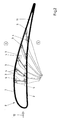
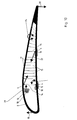
- the rib 1 consists essentially of a flexible closed outer belt 2 and a plurality of length-constant stiffening struts 3.
- the stiffening struts 3 each engage the outer belt 2 at their two ends.
- the joints 4 can as indicated in Figure 1 in several parts or by one particularly flexible area of a single part be.
- the areas of attack of the stiffening struts 3 on the Outer belts 2 have no joints as a whole due to the joints 4 significant bending stiffness.
- the stiffening struts 3 compared to the outer belt 2 extremely stiff and prevent the outer belt 2 from being compressed under the Influence of external forces.
- the stiffening struts 3 but arranged so that it is a targeted Allow rib 1 to deform. This is the Increase in the curvature between Figure 1a and Figure 1b.
- Concrete the stiffening struts do not cross and the spacing of the Attack areas of the stiffening struts 3 on the outer belt 2 are smaller on an overpressure side 5 of the rib 1 than on a vacuum side 6 of the rib 1.
- the curvature of the rib 1 changes the inclination angles 7 and 8 between the outer belt 2 and the stiffening struts 3.
- the in Figure 1 drawn inclination angles 7 and 8 take increasing curvature of the rib 1.
- This relationship between the curvature of the rib 1 and the Inclination angles 7 and 8 are in the aerodynamic component 9 used for arbitrary change of the curvature according to Figure 2.
- the actuators 10 can be known ones mechanical actuators based on, for example Trade piezo crystals or magnetostrictive materials.
- the Rib 1 is covered with an outer skin 11 and firmly connected.
- the outer skin 11 forms the outer surface of the aerodynamic Component 9.
- the actuators 10 are each in the Range of smaller angles of inclination to the outer belt 2 of the Rib 1 arranged because here more favorable installation conditions and because the leverage for one Bending of the outer belt 2 are cheaper.
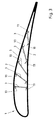
- a rib 1 are the transition areas 12 between the stiffening struts 3 and the outer belt 2 are rigid. That is, there are no joints 4 as in the embodiment provided according to Figures 1 and 2. Rather are Material reinforcements are present to prevent the stiffening struts from kinking 3 to prevent in these attack areas.
- the Embodiment of the rib 1 according to Figure 3 has the advantage that the bending stiffness is significantly greater than in the embodiment according to Figures 1 and 2. This means of course also that a deformation to change the curvature of the rib 1 can only be initiated with greater forces than the Embodiment according to FIGS. 1 and 2.
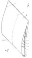
- Figure 4 is a perspective view of a portion of the aerodynamic component 9, that is, the one used here as an example Flap.
- the visible components of the front rib 1 is shown in simplified form.
- In the main direction of extension of the aerodynamic component 9 are on the side several ribs 1 arranged side by side and each firmly with the outer skin 11 connected.
- the outer belt 2 of the visible rib 1 in one piece formed with the outer skin 11 or integrated into this.
- the stiffening struts 3 engage in reinforce Attack areas 13 directly on the outer skin 11, the also forms the outer belt. This will make one more lighter structure of the aerodynamic component 9 achieved than in the embodiment according to FIGS. 1 to 5.
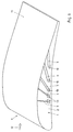
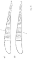
- the rib 1 shown in FIG. 7 has two types of length constants Stiffening struts 3.
- Two stiffening struts 3 are designed as main struts 14, while the others Form stiffening struts 3 secondary struts 15.
- the main struts 14 are particularly stable and designed for Storage of the rib 1 on a supporting structure 16, which is in shape taut areas is indicated, provided. Warehousing the rib 1 on the supporting structure 16 is for removing the on the rib 1 over the outer skin, not shown here acting aerodynamic forces necessary.
- the secondary struts 15 between the main struts 14 are parallel to each other and arranged parallel to the main struts 14.
- the secondary struts 15 behind the rear main strut 14 are with increasing inclination arranged.
- the connections between the stiffening struts 3 and the outer belt 2 are as flexible Realizing connections. At the main struts 14 there are joints 4 intended. In the secondary struts 15, the connections are as Target bending points 17 formed, which is due to the smaller here Load is sufficient.
- FIG. 8 shows a possible connection of the rib 1 to the supporting structure 16.
- the spars are 16 in the area of the lower joints 4 with the main spokes 14 and so connected to the entire rib 1.
- the outer belt is supported 2 from the bottom of the bars 16.
- Figure 8 is also the outer skin 11 of the aerodynamic component 9 is shown, being divided into a bottom and a top.
- FIG. 9 shows the rib 1 according to FIG. 7 in the deformed state, the undeformed rib 1 is shown in the background.
- the change in curvature of the rib 1 in its rear arch area can be clearly seen.
- Due to the special arrangement the stiffening struts 3 results in relation to the outer belt 2 the deformation shown in Figure 9 is relatively independent where the forces for the deformation are applied. It there is therefore a multitude of possible approaches for Actuators, and the rib 1 is not in any particular way or How actuators work.
- Figure 10 outlines various attack options for actuators on the rib 1 according to FIG. 7 in order to change the shape according to FIG Figure 9 to achieve.
- An arrow 19 indicates how in the nose area the rib the deformation by an upward Power can be achieved.
- an aerodynamic Actuator in the form of an activatable flap.
- Corresponding indicates an arrow 20, as in the rear edge area of the rib 1 due to a downward force the deformation also can be reached.
- An arrow 21 stands for an actuator between a spar 18 of the supporting structure 16 and the front Main strut 14.
- Arrows 22 stand for the attack of one Actuator between the upper joint 4 of the front main strut 14 and the lower joint 4 of the rear main strut 14.
- a Arrow 23 stands for an active joint between the outer belt 2 and the front main strut 14 in the lower Area or for one around the lower joint 4 of the front Main strut 14 acting actuator.
- Another arrow 24 stands for a structure-integrated actuator system in the rear Vaulted area.
- the model refers to the high lift flap of a large one Airliner.
- Figure 5 shows the deformation due to a horizontal force from 2,600 N to the front main spoke approximately in the direction of the Arrow 21 according to FIG. 10.
- the vertical deflection 25 of the rib 1 at its rear edge is in both cases about 47 mm, but in different directions.
- the result of a further FEM simulation shown in FIG. 12 refers to the shape stability of the rib 1 according to Figure 7 with the above data against external forces. Based on is a typical operating load of the order of magnitude of 3,000 N / m. The resulting maximum deflection the profile of the rib 1 is greatly enlarged in FIG shown and is nowhere in the vertical direction more than 3 mm. That is, the passive deformation of the rib 1 by operating loads is more than an order of magnitude smaller than the desired deformation of the rib 1 according to FIG. 11.
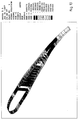
- Figure 13 shows the result of a further FEM calculation.
- the calculation is based on the maximum load, with which is to be expected in operation (maneuver load), provided with a Safety factor of 1.5. This results in a nominal burden of approx.8,000 N / m.
- the maximum elongation is Area of the belt 2 and the stiffening struts 3 less than 0.34% and is therefore in the uncritical range.
- the rib 1 according to FIG. 7 has a particularly favorable energy balance in the event of an actuator attack for the purpose of their deformation on.
- By arranging the stiffening struts 3 under aerodynamic Viewpoints is caused to the direction of Deflection in wide areas of the profile opposite to Direction in the arch area. This causes part of the mechanical work, for example to lower the Vaulted area is required over the other areas of the Profile from aerodynamic forces due to the inflow of the respective aerodynamic component is obtained.
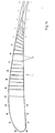
- Figure 14 are the areas in which the shape change opposes aerodynamic forces occur marked with a minus sign, while the areas where the shape change Supporting aerodynamic forces appear with a plus sign are marked. The relatively larger proportion of those with plus signs marked areas makes it clear that the possibility consists of gaining energy here for the deformation of the Rib 1 is required. Up to 50% of the required Total energy can be obtained from this.
- Figure 15 outlines as by aerodynamic actuators 26 in the Nose and / or trailing edge area of the rib 1 additional aerodynamic forces can be generated to exclusively to bring about the desired change in shape of the rib 1.
- the aerodynamic actuators 26 can For example, act on flaps that can be activated, which are in different Angles to the outer belt 2 of the rib 1 adjustable are. This means that aerodynamic forces are in the direction of arrows 19 and 20 according to FIG. 10 or opposite to these arrows provocable. However, the aerodynamic actuators 26 are not suitable for preserving a change in shape of the rib 1.
- An additional locking device 27 is provided for this, here between the front spar 18 of the load-bearing Structure 16 and the front main strut 14 acts.
- the aerodynamic actuators 26 are only needed as long and accordingly only activated until the desired change in shape is brought about. Then the shape change with the locking device 27 fixed. Then you can aerodynamic actuators 26 back to their neutral position can be traced back to, for example, no unwanted cause additional flow friction.
- the flap-shaped Aerodynamic actuators according to FIG. 15 are for example also actively deformable surface elements of the aerodynamic Component with integrated solid state actuators conceivable.
- Rib 1 has two coupling mechanisms 28 and 29, one area of the outer belt 2 optionally with the supporting structure 16 or with a superordinate structure 30, for example with the Wing box of the wing on which the high-lift flap is mounted is to connect firmly.
- the coupling mechanisms 28 and 29 can For example, be designed as a brake or clutch.
- the high-lift flap is due to the existing flap drive retracted while the coupling mechanism between the Outer belt and the parent structure 30 is active, so the outer belt deforms so that the rear arch area arches ( Figure 16 b)). Now the coupling mechanism 28 activated with the supporting structure 16 and the coupling mechanism 29 deactivated, the high lift flap in deformed state returned to the original position be ( Figure 16 c)). With a similar concept, too other aerodynamic components, such as. B. transverse, vertical or Rudder, are operated with regard to their deformation.
Landscapes
- Engineering & Computer Science (AREA)
- Mechanical Engineering (AREA)
- Aviation & Aerospace Engineering (AREA)
- Aerodynamic Tests, Hydrodynamic Tests, Wind Tunnels, And Water Tanks (AREA)
Applications Claiming Priority (2)
| Application Number | Priority Date | Filing Date | Title |
|---|---|---|---|
| DE19707392 | 1997-02-25 | ||
| DE19707392A DE19707392A1 (de) | 1997-02-25 | 1997-02-25 | Aerodynamisches Bauteil, wie Landeklappe, Tragflügel, Höhen- oder Seitenleitwerk, mit veränderbarer Wölbung |
Publications (2)
| Publication Number | Publication Date |
|---|---|
| EP0860355A1 true EP0860355A1 (fr) | 1998-08-26 |
| EP0860355B1 EP0860355B1 (fr) | 2003-08-20 |
Family
ID=7821340
Family Applications (1)
| Application Number | Title | Priority Date | Filing Date |
|---|---|---|---|
| EP98103090A Expired - Lifetime EP0860355B1 (fr) | 1997-02-25 | 1998-02-21 | Structure aerodynamique à courbure variable telle que volets d'atterrissage, aile, empennage horizontal et vertical |
Country Status (4)
| Country | Link |
|---|---|
| US (1) | US6010098A (fr) |
| EP (1) | EP0860355B1 (fr) |
| DE (2) | DE19707392A1 (fr) |
| ES (1) | ES2203839T3 (fr) |
Cited By (23)
| Publication number | Priority date | Publication date | Assignee | Title |
|---|---|---|---|---|
| GB2331734A (en) * | 1997-07-31 | 1999-06-02 | Daimler Benz Ag | Aerofoil having a movable and bendable landing flap |
| EP1040999A2 (fr) | 1999-04-01 | 2000-10-04 | Leif Kniese | Elément de support de charges avec enveloppe extérieure souple |
| DE10202440C1 (de) * | 2002-01-22 | 2003-10-02 | Eads Deutschland Gmbh | Gelenk zur Verbindung einer Längsseite mit einer Oberseite von Bauteilen sowie flexibles Band zur Verwendung für ein derartiges Gelenk |
| DE10202439C1 (de) * | 2002-01-22 | 2003-12-04 | Eads Deutschland Gmbh | Gelenk zur Verbindung von Bauteilen mit einander zugewandten Längsseiten sowie flexibles Band zur Verwendung für ein derartiges Gelenk |
| US6986549B2 (en) | 2003-03-19 | 2006-01-17 | Leif Kniese | Seating element |
| US7108231B2 (en) | 2003-04-14 | 2006-09-19 | Eads Deutschland Gmbh | Adjustment mechanism for a variable-shape wing |
| WO2007071384A3 (fr) * | 2005-12-21 | 2007-08-09 | Airbus Gmbh | Surface de commande flexible pour aeronef |
| WO2008006831A1 (fr) * | 2006-07-11 | 2008-01-17 | Airbus Deutschland Gmbh | Plan horizontal réglable |
| WO2008128780A1 (fr) | 2007-04-18 | 2008-10-30 | Rudolf Bannasch | Pale battante courbée et dispositif d'entraînement pour une pale battante courbée |
| USD591986S1 (en) | 2007-09-21 | 2009-05-12 | Herman Miller, Inc. | Body support structure |
| WO2011089277A1 (fr) | 2010-01-20 | 2011-07-28 | Soluciones Energeticas, S.A. | Pale de profil et de forme variables |
| US8156995B2 (en) | 2009-04-20 | 2012-04-17 | Rite-Hite Holding Corporation | Door element |
| US8967726B2 (en) | 2007-09-20 | 2015-03-03 | Herman Miller, Inc. | Load support structure |
| US9534373B2 (en) | 2013-07-02 | 2017-01-03 | Rite-Hite Holding Corporation | Vehicle-actuated weather barrier apparatus |
| DE102019100756A1 (de) | 2019-01-14 | 2020-07-16 | A. Monforts Textilmaschinen Gmbh & Co. Kg | Vorrichtung zum Behandeln einer Warenbahn |
| US10874220B2 (en) | 2015-01-16 | 2020-12-29 | Herman Miller, Inc. | Zoned suspension seating structure |
| CN112498661A (zh) * | 2020-12-04 | 2021-03-16 | 中国航空工业集团公司沈阳飞机设计研究所 | 一种多功能舵面结构 |
| US10966527B2 (en) | 2017-06-09 | 2021-04-06 | Steelcase Inc. | Seating arrangement and method of construction |
| US11096497B2 (en) | 2015-04-13 | 2021-08-24 | Steelcase Inc. | Seating arrangement |
| US11109683B2 (en) | 2019-02-21 | 2021-09-07 | Steelcase Inc. | Body support assembly and method for the use and assembly thereof |
| US11259637B2 (en) | 2015-04-13 | 2022-03-01 | Steelcase Inc. | Seating arrangement |
| US11324325B2 (en) | 2015-04-13 | 2022-05-10 | Steelcase Inc. | Seating arrangement |
| US11357329B2 (en) | 2019-12-13 | 2022-06-14 | Steelcase Inc. | Body support assembly and methods for the use and assembly thereof |
Families Citing this family (48)
| Publication number | Priority date | Publication date | Assignee | Title |
|---|---|---|---|---|
| US6164598A (en) * | 1999-03-10 | 2000-12-26 | Northrop Grumman Corporation | Adaptive control surface apparatus |
| DE10017332C2 (de) * | 2000-04-07 | 2002-04-18 | Daimler Chrysler Ag | Piezoelektrische Betätigungseinrichtung zur Klappensteuerung am Rotorblatt eines Hubschraubers |
| DE10055961B4 (de) | 2000-11-11 | 2004-09-09 | Eads Deutschland Gmbh | Variabler Flügelbereich mit einstellbarer, sich in Spannweiten-Richtung erstreckender Profilform |
| US6481667B1 (en) * | 2001-03-05 | 2002-11-19 | Northrop Grumman Corporation | System and method for deflecting an aerodynamic control surface |
| DE10325950A1 (de) * | 2003-06-07 | 2005-01-05 | Airbus Deutschland Gmbh | Flügel, insbesondere Tragflügel eines Flugzeugs, mit veränderbarem Profil |
| GB0414874D0 (en) * | 2004-07-02 | 2004-08-04 | Rolls Royce Plc | Adaptable fluid flow device |
| DE502005001475D1 (de) * | 2004-12-22 | 2007-10-25 | Airbus Deutschland Gmbh Hrb 43527 | Tragwerk einer aerodynamischen Wirkfläche eines Flugzeugs |
| DE102004062998B4 (de) * | 2004-12-22 | 2010-09-09 | Airbus Deutschland Gmbh | Flügel, insbesondere Tragflügel eines Flugzeugs, mit veränderlicher Profilform |
| US7443078B1 (en) * | 2005-04-25 | 2008-10-28 | E3 Enterprises Lp | Piezo action applied |
| FR2898865B1 (fr) * | 2006-03-27 | 2008-05-30 | Cetim Cermat Ass Loi De 1901 | Profil aerodynamique ou hydrodynamique pouvant etre deforme de maniere continue et controlee |
| GB0624580D0 (en) * | 2006-12-08 | 2007-01-17 | Imp Innovations Ltd | Aerofoil member |
| FR2911202B1 (fr) * | 2007-01-05 | 2009-02-13 | Airbus France Sas | Procede d'optimisation de panneaux raidis sous contraintes ' |
| US7777165B2 (en) * | 2007-02-02 | 2010-08-17 | Raytheon Company | Methods and apparatus for adjustable surfaces |
| DE102007013289B4 (de) * | 2007-03-16 | 2010-02-04 | Eurocopter Deutschland Gmbh | Profilverformung am Beispiel Rotorblatt |
| GB0709118D0 (en) * | 2007-05-14 | 2007-06-20 | Airbus Uk Ltd | Reinforced panel |
| US7939178B2 (en) * | 2008-05-14 | 2011-05-10 | Raytheon Company | Shape-changing structure with superelastic foam material |
| US8382042B2 (en) * | 2008-05-14 | 2013-02-26 | Raytheon Company | Structure with reconfigurable polymer material |
| US8016249B2 (en) * | 2008-05-14 | 2011-09-13 | Raytheon Company | Shape-changing structure member with embedded spring |
| US8267654B2 (en) * | 2008-05-16 | 2012-09-18 | Frontier Wind, Llc | Wind turbine with gust compensating air deflector |
| US8192161B2 (en) * | 2008-05-16 | 2012-06-05 | Frontier Wind, Llc. | Wind turbine with deployable air deflectors |
| US20100148011A1 (en) * | 2008-11-12 | 2010-06-17 | Sanderson Terry M | Telescoping structure and method |
| US8262032B2 (en) * | 2008-11-13 | 2012-09-11 | Raytheon Company | Collapsible wing beams and method |
| US8056853B2 (en) * | 2008-11-25 | 2011-11-15 | Raytheon Company | Reconfigurable wing and method of use |
| US8113470B1 (en) * | 2008-12-02 | 2012-02-14 | Motosko Iii Stephen | Variable air foil and spoiler |
| US8500060B2 (en) * | 2009-02-10 | 2013-08-06 | The Boeing Company | Aircraft with a pressurized vessel |
| US8056865B2 (en) | 2009-03-05 | 2011-11-15 | The Boeing Company | Mechanism for changing the shape of a control surface |
| US9944356B1 (en) | 2009-03-25 | 2018-04-17 | Alexander T. Wigley | Shape shifting foils |
| US8573535B2 (en) * | 2009-03-27 | 2013-11-05 | Raytheon Company | Shape-change material and method |
| US8206107B2 (en) * | 2009-04-13 | 2012-06-26 | Frontier Wind, Llc | Variable length wind turbine blade having transition area elements |
| DE102009026457A1 (de) * | 2009-05-25 | 2010-12-09 | Eads Deutschland Gmbh | Aerodynamisches Bauteil mit verformbarer Außenhaut |
| US8382045B2 (en) | 2009-07-21 | 2013-02-26 | The Boeing Company | Shape-changing control surface |
| DE102010047918A1 (de) | 2010-10-08 | 2014-04-30 | Smart Blade Gmbh | Flexible Hinterkante eines Rotorblattes einer Windkraftanlage |
| US8650811B2 (en) | 2011-02-04 | 2014-02-18 | The Boeing Company | Solar collector frame |
| WO2013027388A1 (fr) * | 2011-08-23 | 2013-02-28 | 三菱航空機株式会社 | Bord d'attaque, aile d'aéronef, pale mobile d'aéronef, et aéronef |
| US9156559B2 (en) * | 2011-10-19 | 2015-10-13 | The Boeing Company | Segmented aircraft wing having solar arrays |
| WO2013066439A1 (fr) | 2011-11-04 | 2013-05-10 | Raytheon Company | Ailes de véhicules aériens à extension de corde |
| HK1205078A1 (zh) * | 2011-11-16 | 2015-12-11 | 瑞德优斯实验室有限公司 | 用於垂直/短距起飛及着陸的方法及設備 |
| US9555871B2 (en) * | 2012-03-05 | 2017-01-31 | The Boeing Company | Two-surface sandwich structure for accommodating in-plane expansion of one of the surfaces relative to the opposing surface |
| USD714712S1 (en) | 2012-11-28 | 2014-10-07 | Robert Reginald Bray | Wingsail propelled boat |
| DE102013202036A1 (de) * | 2013-02-07 | 2014-08-07 | Robert Bosch Gmbh | Windabweiservorrichtung |
| USD720280S1 (en) | 2013-05-06 | 2014-12-30 | Robert Reginald Bray | Wingsail |
| DE102013011915A1 (de) * | 2013-07-17 | 2015-01-22 | Airbus Defence and Space GmbH | Veränderbares Flügelprofil |
| WO2017151580A1 (fr) * | 2016-02-29 | 2017-09-08 | Flexsys, Inc. | Agencement de morphage de bord destiné à une surface portante |
| US11021242B2 (en) | 2016-08-11 | 2021-06-01 | The Hayden Effect, Llc | Apparatus for providing rail-based vertical short takeoff and landing and operational control |
| DE102017216399A1 (de) * | 2017-09-15 | 2019-03-21 | Airbus Operations Gmbh | Steuerfläche für ein Luftfahrzeug und Luftfahrzeug mit flexibler Steuerfläche |
| WO2020257670A1 (fr) * | 2019-06-19 | 2020-12-24 | The Texas A&M University System | Surfaces portantes d'aéronef comprenant des ensembles ondulations, systèmes comprenant des ensembles ondulations et procédés d'utilisation correspondants |
| US11352124B2 (en) * | 2019-11-01 | 2022-06-07 | The Boeing Company | Continuous skin leading edge slats |
| GB2605151A (en) * | 2021-03-24 | 2022-09-28 | Airbus Operations Ltd | An aircraft wing trailing edge section assembly |
Citations (10)
| Publication number | Priority date | Publication date | Assignee | Title |
|---|---|---|---|---|
| FR554771A (fr) * | 1922-08-04 | 1923-06-16 | Nervure à courbure variable pour surfaces portantes d'appareils aériens | |
| US2022806A (en) * | 1933-12-09 | 1935-12-03 | Charles H Grant | Airfoil |
| US3179357A (en) | 1962-02-27 | 1965-04-20 | Donald G Lyon | Variable shaped airfoil |
| US3716202A (en) | 1971-01-13 | 1973-02-13 | Mississippi State University D | Magnetically attracted bobbins |
| US3987984A (en) | 1973-04-09 | 1976-10-26 | Albert George Fischer | Semi-rigid aircraft wing |
| FR2445267A1 (fr) * | 1978-12-29 | 1980-07-25 | Philippe Marc | Propulseur aerodynamique epais a courbure commandee, reversible et affalable |
| US4341176A (en) * | 1980-09-29 | 1982-07-27 | Orrison William W | Air foil with reversible camber |
| US4349169A (en) | 1980-08-14 | 1982-09-14 | The United States Of America As Represented By The Secretary Of The Air Force | Continuous force actuator |
| US4865275A (en) * | 1986-08-11 | 1989-09-12 | Alpha Images, Ltd. | Land, water and air craft |
| WO1994026588A1 (fr) * | 1993-05-06 | 1994-11-24 | Grumman Aerospace Corporation | Appareil et procede de regulation de profil de structures |
Family Cites Families (10)
| Publication number | Priority date | Publication date | Assignee | Title |
|---|---|---|---|---|
| DE366693C (de) * | 1915-10-29 | 1923-01-10 | Varioplane Company Ltd | Tragflaeche fuer Flugzeuge |
| FR536494A (fr) * | 1921-06-06 | 1922-05-04 | Aile métallique à courbure et incidence variables, pour aéroplanes | |
| FR770113A (fr) * | 1934-03-13 | 1934-09-08 | Aile d'avion à profil variable | |
| US3076623A (en) * | 1960-10-19 | 1963-02-05 | Donald G Lyon | Variable shaped airfoil |
| US3716209A (en) * | 1970-06-01 | 1973-02-13 | Mini Of Technology | Fluid dynamic lift generating or control force generating structures |
| DE2907912C2 (de) * | 1979-03-01 | 1985-06-05 | Dornier Gmbh, 7990 Friedrichshafen | Quertriebskörper mit veränderbarer Profilierung, insbesondere Nasenteile von Flugzeugtragflügeln |
| US4386574A (en) * | 1981-12-15 | 1983-06-07 | Riolland Pierre L | Sail assembly of variable profile, reversible and collapsible |
| US5360682A (en) * | 1992-08-17 | 1994-11-01 | Display Matrix Corporation | Battery charge indicator apparatus and the method of operation thereof |
| GB9317294D0 (en) * | 1993-08-19 | 1993-10-20 | Westland Helicopters | Circulation control aerofoils |
| US5626312A (en) * | 1994-07-06 | 1997-05-06 | Mcdonnell Douglas Corporation | Piezoelectric actuator |
-
1997
- 1997-02-25 DE DE19707392A patent/DE19707392A1/de not_active Withdrawn
-
1998
- 1998-02-21 EP EP98103090A patent/EP0860355B1/fr not_active Expired - Lifetime
- 1998-02-21 ES ES98103090T patent/ES2203839T3/es not_active Expired - Lifetime
- 1998-02-21 DE DE59809308T patent/DE59809308D1/de not_active Expired - Lifetime
- 1998-02-24 US US09/028,606 patent/US6010098A/en not_active Expired - Lifetime
Patent Citations (11)
| Publication number | Priority date | Publication date | Assignee | Title |
|---|---|---|---|---|
| FR554771A (fr) * | 1922-08-04 | 1923-06-16 | Nervure à courbure variable pour surfaces portantes d'appareils aériens | |
| US2022806A (en) * | 1933-12-09 | 1935-12-03 | Charles H Grant | Airfoil |
| US3179357A (en) | 1962-02-27 | 1965-04-20 | Donald G Lyon | Variable shaped airfoil |
| US3716202A (en) | 1971-01-13 | 1973-02-13 | Mississippi State University D | Magnetically attracted bobbins |
| US3987984A (en) | 1973-04-09 | 1976-10-26 | Albert George Fischer | Semi-rigid aircraft wing |
| FR2445267A1 (fr) * | 1978-12-29 | 1980-07-25 | Philippe Marc | Propulseur aerodynamique epais a courbure commandee, reversible et affalable |
| US4349169A (en) | 1980-08-14 | 1982-09-14 | The United States Of America As Represented By The Secretary Of The Air Force | Continuous force actuator |
| US4341176A (en) * | 1980-09-29 | 1982-07-27 | Orrison William W | Air foil with reversible camber |
| US4865275A (en) * | 1986-08-11 | 1989-09-12 | Alpha Images, Ltd. | Land, water and air craft |
| WO1994026588A1 (fr) * | 1993-05-06 | 1994-11-24 | Grumman Aerospace Corporation | Appareil et procede de regulation de profil de structures |
| US5531407A (en) | 1993-05-06 | 1996-07-02 | Grumman Aerospace Corporation | Apparatus and method for controlling the shape of structures |
Cited By (55)
| Publication number | Priority date | Publication date | Assignee | Title |
|---|---|---|---|---|
| GB2331734B (en) * | 1997-07-31 | 2002-01-16 | Daimler Benz Ag | Aerofoil having a landing flap |
| GB2331734A (en) * | 1997-07-31 | 1999-06-02 | Daimler Benz Ag | Aerofoil having a movable and bendable landing flap |
| EP1316651A3 (fr) * | 1999-04-01 | 2004-01-02 | Leif Kniese | Elément de support de charges avec enveloppe extérieure souple |
| EP1040999A2 (fr) | 1999-04-01 | 2000-10-04 | Leif Kniese | Elément de support de charges avec enveloppe extérieure souple |
| DE19916411A1 (de) * | 1999-04-01 | 2000-11-16 | Leif Kniese | Dynamischer Hebel zur Verbesserung der Kraftübertragung |
| EP1040999A3 (fr) * | 1999-04-01 | 2002-08-28 | Leif Kniese | Elément de support de charges avec enveloppe extérieure souple |
| EP2327623A1 (fr) | 1999-04-01 | 2011-06-01 | Leif Kniese | Chaise |
| US7451950B2 (en) | 2002-01-22 | 2008-11-18 | Airbus Deutschland Gmbh | Joint for connecting a longitudinal side to an upper side of components and flexible strip for use in such a joint |
| US7425103B2 (en) | 2002-01-22 | 2008-09-16 | Airbus Deutschland Gmbh | Joint for connecting components together on opposite longitudinal sides in addition to a flexible strip used for said joint |
| DE10202440C1 (de) * | 2002-01-22 | 2003-10-02 | Eads Deutschland Gmbh | Gelenk zur Verbindung einer Längsseite mit einer Oberseite von Bauteilen sowie flexibles Band zur Verwendung für ein derartiges Gelenk |
| US7900878B2 (en) | 2002-01-22 | 2011-03-08 | Airbus Deutschland Gmbh | Joint for connecting a longitudinal side to an upper side of components and flexible strip for use in such a joint |
| DE10202439C1 (de) * | 2002-01-22 | 2003-12-04 | Eads Deutschland Gmbh | Gelenk zur Verbindung von Bauteilen mit einander zugewandten Längsseiten sowie flexibles Band zur Verwendung für ein derartiges Gelenk |
| US6986549B2 (en) | 2003-03-19 | 2006-01-17 | Leif Kniese | Seating element |
| US7108231B2 (en) | 2003-04-14 | 2006-09-19 | Eads Deutschland Gmbh | Adjustment mechanism for a variable-shape wing |
| WO2007071384A3 (fr) * | 2005-12-21 | 2007-08-09 | Airbus Gmbh | Surface de commande flexible pour aeronef |
| RU2408498C2 (ru) * | 2005-12-21 | 2011-01-10 | Эрбус Оперейшнс Гмбх | Гибкая управляющая поверхность для летательного аппарата |
| US7963485B2 (en) | 2006-07-11 | 2011-06-21 | Airbus Operations Gmbh | Trimmable horizontal stabilizer |
| WO2008006831A1 (fr) * | 2006-07-11 | 2008-01-17 | Airbus Deutschland Gmbh | Plan horizontal réglable |
| DE102006032003B4 (de) * | 2006-07-11 | 2015-10-22 | Airbus Operations Gmbh | Trimmbares Höhenleitwerk |
| WO2008128780A1 (fr) | 2007-04-18 | 2008-10-30 | Rudolf Bannasch | Pale battante courbée et dispositif d'entraînement pour une pale battante courbée |
| US8967726B2 (en) | 2007-09-20 | 2015-03-03 | Herman Miller, Inc. | Load support structure |
| US10820706B2 (en) | 2007-09-20 | 2020-11-03 | Herman Miller, Inc. | Load support structure |
| US9668580B2 (en) | 2007-09-20 | 2017-06-06 | Herman Miller, Inc. | Load support structure |
| US11330905B2 (en) | 2007-09-20 | 2022-05-17 | MillerKnoll, Inc. | Load support structure |
| US10856662B2 (en) | 2007-09-20 | 2020-12-08 | Herman Miller, Inc. | Load support structure |
| US10016060B2 (en) | 2007-09-20 | 2018-07-10 | Herman Miller, Inc. | Load support structure |
| USD591986S1 (en) | 2007-09-21 | 2009-05-12 | Herman Miller, Inc. | Body support structure |
| US8156995B2 (en) | 2009-04-20 | 2012-04-17 | Rite-Hite Holding Corporation | Door element |
| US8540007B2 (en) | 2009-04-20 | 2013-09-24 | Rite-Hite Holding Corporation | Door element |
| WO2011089277A1 (fr) | 2010-01-20 | 2011-07-28 | Soluciones Energeticas, S.A. | Pale de profil et de forme variables |
| US9534373B2 (en) | 2013-07-02 | 2017-01-03 | Rite-Hite Holding Corporation | Vehicle-actuated weather barrier apparatus |
| US9797128B2 (en) | 2013-07-02 | 2017-10-24 | Rite-Hite Holding Corporation | Vehicle-actuated weather barrier apparatus |
| US9797127B2 (en) | 2013-07-02 | 2017-10-24 | Rite-Hite-Holding Corporation | Vehicle-actuated weather barrier apparatus |
| US11825957B2 (en) | 2015-01-16 | 2023-11-28 | MillerKnoll, Inc. | Zoned suspension seating structure |
| US10874220B2 (en) | 2015-01-16 | 2020-12-29 | Herman Miller, Inc. | Zoned suspension seating structure |
| US11553797B2 (en) | 2015-04-13 | 2023-01-17 | Steelcase Inc. | Seating arrangement |
| US11324325B2 (en) | 2015-04-13 | 2022-05-10 | Steelcase Inc. | Seating arrangement |
| US11096497B2 (en) | 2015-04-13 | 2021-08-24 | Steelcase Inc. | Seating arrangement |
| US11963621B2 (en) | 2015-04-13 | 2024-04-23 | Steelcase Inc. | Seating arrangement |
| US11259637B2 (en) | 2015-04-13 | 2022-03-01 | Steelcase Inc. | Seating arrangement |
| US11825955B2 (en) | 2017-06-09 | 2023-11-28 | Steelcase Inc. | Seating arrangement and method of construction |
| US12582234B2 (en) | 2017-06-09 | 2026-03-24 | Steelcase Inc. | Seating arrangement |
| US10966527B2 (en) | 2017-06-09 | 2021-04-06 | Steelcase Inc. | Seating arrangement and method of construction |
| DE102019100756A1 (de) | 2019-01-14 | 2020-07-16 | A. Monforts Textilmaschinen Gmbh & Co. Kg | Vorrichtung zum Behandeln einer Warenbahn |
| WO2020148033A1 (fr) | 2019-01-14 | 2020-07-23 | A. Monforts Textilmaschinen Gmbh & Co. Kg | Dispositif de traitement d'une bande de matériau |
| US11602223B2 (en) | 2019-02-21 | 2023-03-14 | Steelcase Inc. | Body support assembly and methods for the use and assembly thereof |
| US11910934B2 (en) | 2019-02-21 | 2024-02-27 | Steelcase Inc. | Body support assembly and methods for the use and assembly thereof |
| US11109683B2 (en) | 2019-02-21 | 2021-09-07 | Steelcase Inc. | Body support assembly and method for the use and assembly thereof |
| US12226025B2 (en) | 2019-02-21 | 2025-02-18 | Steelcase Inc. | Body support assembly and methods for the use and assembly thereof |
| US11805913B2 (en) | 2019-12-13 | 2023-11-07 | Steelcase Inc. | Body support assembly and methods for the use and assembly thereof |
| US11786039B2 (en) | 2019-12-13 | 2023-10-17 | Steelcase Inc. | Body support assembly and methods for the use and assembly thereof |
| US12161232B2 (en) | 2019-12-13 | 2024-12-10 | Steelcase Inc. | Body support assembly and methods for the use and assembly thereof |
| US11357329B2 (en) | 2019-12-13 | 2022-06-14 | Steelcase Inc. | Body support assembly and methods for the use and assembly thereof |
| CN112498661A (zh) * | 2020-12-04 | 2021-03-16 | 中国航空工业集团公司沈阳飞机设计研究所 | 一种多功能舵面结构 |
| CN112498661B (zh) * | 2020-12-04 | 2024-01-30 | 中国航空工业集团公司沈阳飞机设计研究所 | 一种多功能舵面结构 |
Also Published As
| Publication number | Publication date |
|---|---|
| DE19707392A1 (de) | 1998-08-27 |
| ES2203839T3 (es) | 2004-04-16 |
| DE59809308D1 (de) | 2003-09-25 |
| US6010098A (en) | 2000-01-04 |
| EP0860355B1 (fr) | 2003-08-20 |
Similar Documents
| Publication | Publication Date | Title |
|---|---|---|
| EP0860355B1 (fr) | Structure aerodynamique à courbure variable telle que volets d'atterrissage, aile, empennage horizontal et vertical | |
| EP1674389B1 (fr) | Structure pour une surface aérodynamique active d'un aéronef | |
| DE19741326C2 (de) | Anströmprofil mit variabler Profiladaption | |
| DE102004062998B4 (de) | Flügel, insbesondere Tragflügel eines Flugzeugs, mit veränderlicher Profilform | |
| EP1636086B1 (fr) | Aile, notamment aile porteuse d'un avion, ayant un profil modifiable | |
| DE19653851C2 (de) | Aerodynamischer Körper mit innenliegenden Stellantrieben | |
| DE102007044388A1 (de) | Druckschott und Verfahren zum Unterteilen eines Luft- oder Raumfahrzeugs | |
| EP3022116B1 (fr) | Profil d'aile variable | |
| EP2733063B1 (fr) | Structure de morphing pour un bord d'attaque d'une aile d'avion | |
| EP2280867B1 (fr) | Dispositif de couplage latéral pour maintenir et guider au moins un corps aérodynamique par rapport à une aile principale d'un aéronef, voilure et aéronef comprenant ledit dispositif | |
| DE102008025414A1 (de) | Aerodynamisches Profil mit reversibel verformbarer Kontur für Luftfahrzeuge, insbesondere für Drehflügelflugzeuge | |
| EP2454151B1 (fr) | Enveloppe d'avion ou d'engin spatial | |
| DE102011017460A1 (de) | Faserverbundbauteil, Flügelspitzenverlängerung und Flugzeug mit einem Faserverbundteil | |
| DE102005003296B4 (de) | Rumpfhecksektion eines Flugzeugs | |
| EP1714866B1 (fr) | Aile monocoque | |
| EP3448750B1 (fr) | Corps à profil aérodynamique pour aéronef | |
| DE2923463A1 (de) | Fluegel, insbesondere zur verwendung an rotoren zur windkraftumsetzung | |
| EP2730496B1 (fr) | Composant plat pour aéronef et procédé de sa fabrication | |
| WO2002047976A2 (fr) | Aile aerodynamique a courbure au moins partiellement variable et articulation structurelle | |
| DE102024103686A1 (de) | Aerodynamischer Profilkörper und Flugobjekt hierzu | |
| DE102005038857B4 (de) | Doppelschalig aufgebauter Mittelkasten | |
| DE4404810C2 (de) | Rumpfheck für ein Verkehrsflugzeug | |
| DE102023117337B3 (de) | Aerodynamischer Profilkörper und Flugobjekt | |
| DE102004063093A1 (de) | Tragwerk, insbesondere Holmkasten, zur Bildung von aerodynamischen Wirkflächen von Luftfahrzeugen, insbesondere von Tragflächen, Höhenleitwerken oder Seitenleitwerken von Flugzeugen | |
| DE19748682A1 (de) | Federelement und Stützlager für Hubschreiberheckrotoren und Tragestrukturen zum Einsatz im Weltraum |
Legal Events
| Date | Code | Title | Description |
|---|---|---|---|
| PUAI | Public reference made under article 153(3) epc to a published international application that has entered the european phase |
Free format text: ORIGINAL CODE: 0009012 |
|
| AK | Designated contracting states |
Kind code of ref document: A1 Designated state(s): DE ES FR GB IT |
|
| AX | Request for extension of the european patent |
Free format text: AL;LT;LV;MK;RO;SI |
|
| 17P | Request for examination filed |
Effective date: 19980715 |
|
| AKX | Designation fees paid |
Free format text: DE ES FR GB IT |
|
| RBV | Designated contracting states (corrected) |
Designated state(s): DE ES FR GB IT |
|
| 17Q | First examination report despatched |
Effective date: 20010921 |
|
| GRAH | Despatch of communication of intention to grant a patent |
Free format text: ORIGINAL CODE: EPIDOS IGRA |
|
| GRAH | Despatch of communication of intention to grant a patent |
Free format text: ORIGINAL CODE: EPIDOS IGRA |
|
| GRAA | (expected) grant |
Free format text: ORIGINAL CODE: 0009210 |
|
| AK | Designated contracting states |
Designated state(s): DE ES FR GB IT |
|
| REG | Reference to a national code |
Ref country code: GB Ref legal event code: FG4D Free format text: NOT ENGLISH |
|
| REF | Corresponds to: |
Ref document number: 59809308 Country of ref document: DE Date of ref document: 20030925 Kind code of ref document: P |
|
| GBT | Gb: translation of ep patent filed (gb section 77(6)(a)/1977) |
Effective date: 20031211 |
|
| REG | Reference to a national code |
Ref country code: ES Ref legal event code: FG2A Ref document number: 2203839 Country of ref document: ES Kind code of ref document: T3 |
|
| ET | Fr: translation filed | ||
| PLBE | No opposition filed within time limit |
Free format text: ORIGINAL CODE: 0009261 |
|
| STAA | Information on the status of an ep patent application or granted ep patent |
Free format text: STATUS: NO OPPOSITION FILED WITHIN TIME LIMIT |
|
| 26N | No opposition filed |
Effective date: 20040524 |
|
| PGFP | Annual fee paid to national office [announced via postgrant information from national office to epo] |
Ref country code: ES Payment date: 20140213 Year of fee payment: 17 Ref country code: FR Payment date: 20140128 Year of fee payment: 17 Ref country code: IT Payment date: 20140221 Year of fee payment: 17 |
|
| PGFP | Annual fee paid to national office [announced via postgrant information from national office to epo] |
Ref country code: GB Payment date: 20140128 Year of fee payment: 17 |
|
| REG | Reference to a national code |
Ref country code: DE Ref legal event code: R082 Ref document number: 59809308 Country of ref document: DE Representative=s name: REHBERG HUEPPE + PARTNER PATENTANWAELTE PARTG , DE |
|
| REG | Reference to a national code |
Ref country code: DE Ref legal event code: R082 Ref document number: 59809308 Country of ref document: DE Representative=s name: REHBERG HUEPPE + PARTNER PATENTANWAELTE PARTG , DE Effective date: 20140630 Ref country code: DE Ref legal event code: R081 Ref document number: 59809308 Country of ref document: DE Owner name: CAMPANILE, LUCIO FLAVIO, DR.-ING., CH Free format text: FORMER OWNER: DEUTSCHES ZENTRUM FUER LUFT- UND RAUMFAHRT E.V., 51147 KOELN, DE Effective date: 20140630 |
|
| PGFP | Annual fee paid to national office [announced via postgrant information from national office to epo] |
Ref country code: DE Payment date: 20141217 Year of fee payment: 18 |
|
| GBPC | Gb: european patent ceased through non-payment of renewal fee |
Effective date: 20150221 |
|
| REG | Reference to a national code |
Ref country code: FR Ref legal event code: ST Effective date: 20151030 |
|
| PG25 | Lapsed in a contracting state [announced via postgrant information from national office to epo] |
Ref country code: IT Free format text: LAPSE BECAUSE OF NON-PAYMENT OF DUE FEES Effective date: 20150221 |
|
| PG25 | Lapsed in a contracting state [announced via postgrant information from national office to epo] |
Ref country code: GB Free format text: LAPSE BECAUSE OF NON-PAYMENT OF DUE FEES Effective date: 20150221 |
|
| PG25 | Lapsed in a contracting state [announced via postgrant information from national office to epo] |
Ref country code: FR Free format text: LAPSE BECAUSE OF NON-PAYMENT OF DUE FEES Effective date: 20150302 |
|
| REG | Reference to a national code |
Ref country code: ES Ref legal event code: FD2A Effective date: 20160330 |
|
| PG25 | Lapsed in a contracting state [announced via postgrant information from national office to epo] |
Ref country code: ES Free format text: LAPSE BECAUSE OF NON-PAYMENT OF DUE FEES Effective date: 20150222 |
|
| REG | Reference to a national code |
Ref country code: DE Ref legal event code: R119 Ref document number: 59809308 Country of ref document: DE |
|
| PG25 | Lapsed in a contracting state [announced via postgrant information from national office to epo] |
Ref country code: DE Free format text: LAPSE BECAUSE OF NON-PAYMENT OF DUE FEES Effective date: 20160901 |