EP0860407A2 - Hochgeschwindigkeitsfermentierung- und Trockenapparat von Lebensmittelabfall - Google Patents
Hochgeschwindigkeitsfermentierung- und Trockenapparat von Lebensmittelabfall Download PDFInfo
- Publication number
- EP0860407A2 EP0860407A2 EP97109135A EP97109135A EP0860407A2 EP 0860407 A2 EP0860407 A2 EP 0860407A2 EP 97109135 A EP97109135 A EP 97109135A EP 97109135 A EP97109135 A EP 97109135A EP 0860407 A2 EP0860407 A2 EP 0860407A2
- Authority
- EP
- European Patent Office
- Prior art keywords
- steam
- odor gas
- food garbage
- pipe
- condensed water
- Prior art date
- Legal status (The legal status is an assumption and is not a legal conclusion. Google has not performed a legal analysis and makes no representation as to the accuracy of the status listed.)
- Ceased
Links
Images




Classifications
-
- B—PERFORMING OPERATIONS; TRANSPORTING
- B09—DISPOSAL OF SOLID WASTE; RECLAMATION OF CONTAMINATED SOIL
- B09B—DISPOSAL OF SOLID WASTE NOT OTHERWISE PROVIDED FOR
- B09B3/00—Destroying solid waste or transforming solid waste into something useful or harmless
-
- C—CHEMISTRY; METALLURGY
- C05—FERTILISERS; MANUFACTURE THEREOF
- C05F—ORGANIC FERTILISERS NOT COVERED BY SUBCLASSES C05B, C05C, e.g. FERTILISERS FROM WASTE OR REFUSE
- C05F9/00—Fertilisers from household or town refuse
- C05F9/02—Apparatus for the manufacture
-
- C—CHEMISTRY; METALLURGY
- C05—FERTILISERS; MANUFACTURE THEREOF
- C05F—ORGANIC FERTILISERS NOT COVERED BY SUBCLASSES C05B, C05C, e.g. FERTILISERS FROM WASTE OR REFUSE
- C05F17/00—Preparation of fertilisers characterised by biological or biochemical treatment steps, e.g. composting or fermentation
- C05F17/10—Addition or removal of substances other than water or air to or from the material during the treatment
- C05F17/15—Addition or removal of substances other than water or air to or from the material during the treatment the material being gas
-
- C—CHEMISTRY; METALLURGY
- C05—FERTILISERS; MANUFACTURE THEREOF
- C05F—ORGANIC FERTILISERS NOT COVERED BY SUBCLASSES C05B, C05C, e.g. FERTILISERS FROM WASTE OR REFUSE
- C05F17/00—Preparation of fertilisers characterised by biological or biochemical treatment steps, e.g. composting or fermentation
- C05F17/60—Heating or cooling during the treatment
-
- C—CHEMISTRY; METALLURGY
- C05—FERTILISERS; MANUFACTURE THEREOF
- C05F—ORGANIC FERTILISERS NOT COVERED BY SUBCLASSES C05B, C05C, e.g. FERTILISERS FROM WASTE OR REFUSE
- C05F17/00—Preparation of fertilisers characterised by biological or biochemical treatment steps, e.g. composting or fermentation
- C05F17/90—Apparatus therefor
-
- F—MECHANICAL ENGINEERING; LIGHTING; HEATING; WEAPONS; BLASTING
- F26—DRYING
- F26B—DRYING SOLID MATERIALS OR OBJECTS BY REMOVING LIQUID THEREFROM
- F26B11/00—Machines or apparatus for drying solid materials or objects with movement which is non-progressive
- F26B11/12—Machines or apparatus for drying solid materials or objects with movement which is non-progressive in stationary drums or other mainly-closed receptacles with moving stirring devices
- F26B11/16—Machines or apparatus for drying solid materials or objects with movement which is non-progressive in stationary drums or other mainly-closed receptacles with moving stirring devices the stirring device moving in a vertical or steeply-inclined plane
-
- F—MECHANICAL ENGINEERING; LIGHTING; HEATING; WEAPONS; BLASTING
- F26—DRYING
- F26B—DRYING SOLID MATERIALS OR OBJECTS BY REMOVING LIQUID THEREFROM
- F26B21/00—Arrangements for supplying or controlling air or other gases for drying solid materials or objects
- F26B21/30—Controlling, e.g. regulating, parameters of gas supply
- F26B21/33—Humidity
- F26B21/333—Humidity by condensing the moisture in the drying medium, which may be recycled, e.g. using a heat pump cycle
-
- F—MECHANICAL ENGINEERING; LIGHTING; HEATING; WEAPONS; BLASTING
- F26—DRYING
- F26B—DRYING SOLID MATERIALS OR OBJECTS BY REMOVING LIQUID THEREFROM
- F26B23/00—Heating arrangements
- F26B23/02—Heating arrangements using combustion heating
- F26B23/022—Heating arrangements using combustion heating incinerating volatiles in the dryer exhaust gases, the produced hot gases being wholly, partly or not recycled into the drying enclosure
-
- Y—GENERAL TAGGING OF NEW TECHNOLOGICAL DEVELOPMENTS; GENERAL TAGGING OF CROSS-SECTIONAL TECHNOLOGIES SPANNING OVER SEVERAL SECTIONS OF THE IPC; TECHNICAL SUBJECTS COVERED BY FORMER USPC CROSS-REFERENCE ART COLLECTIONS [XRACs] AND DIGESTS
- Y02—TECHNOLOGIES OR APPLICATIONS FOR MITIGATION OR ADAPTATION AGAINST CLIMATE CHANGE
- Y02A—TECHNOLOGIES FOR ADAPTATION TO CLIMATE CHANGE
- Y02A40/00—Adaptation technologies in agriculture, forestry, livestock or agroalimentary production
- Y02A40/10—Adaptation technologies in agriculture, forestry, livestock or agroalimentary production in agriculture
- Y02A40/20—Fertilizers of biological origin, e.g. guano or fertilizers made from animal corpses
-
- Y—GENERAL TAGGING OF NEW TECHNOLOGICAL DEVELOPMENTS; GENERAL TAGGING OF CROSS-SECTIONAL TECHNOLOGIES SPANNING OVER SEVERAL SECTIONS OF THE IPC; TECHNICAL SUBJECTS COVERED BY FORMER USPC CROSS-REFERENCE ART COLLECTIONS [XRACs] AND DIGESTS
- Y02—TECHNOLOGIES OR APPLICATIONS FOR MITIGATION OR ADAPTATION AGAINST CLIMATE CHANGE
- Y02P—CLIMATE CHANGE MITIGATION TECHNOLOGIES IN THE PRODUCTION OR PROCESSING OF GOODS
- Y02P20/00—Technologies relating to chemical industry
- Y02P20/141—Feedstock
- Y02P20/145—Feedstock the feedstock being materials of biological origin
-
- Y—GENERAL TAGGING OF NEW TECHNOLOGICAL DEVELOPMENTS; GENERAL TAGGING OF CROSS-SECTIONAL TECHNOLOGIES SPANNING OVER SEVERAL SECTIONS OF THE IPC; TECHNICAL SUBJECTS COVERED BY FORMER USPC CROSS-REFERENCE ART COLLECTIONS [XRACs] AND DIGESTS
- Y02—TECHNOLOGIES OR APPLICATIONS FOR MITIGATION OR ADAPTATION AGAINST CLIMATE CHANGE
- Y02W—CLIMATE CHANGE MITIGATION TECHNOLOGIES RELATED TO WASTEWATER TREATMENT OR WASTE MANAGEMENT
- Y02W30/00—Technologies for solid waste management
- Y02W30/40—Bio-organic fraction processing; Production of fertilisers from the organic fraction of waste or refuse
Definitions
- the present invention relates to a fermenting and drying apparatus for food garbage, and more particularly to an apparatus for performing, for a minimum time, the fermentation of food garbage, and the pyrolysis and drying of the food garbage for its quantity decrease and its composting by maximizing effects of the fermentation, and the pyrolysis and drying, and for easily removing offensive odor gas generated during the fermenting step of the food garbage and the pyrolysis and drying step of the food garbage.
- a conventional food garbage - fermenting and drying apparatus has the structure, of a low - temperature and low - speed fermenting and drying method, comprising a food garbage tank, an agitator and a heat - supplying part. Therefore, an additional ferment fungus is added to the food garbage in order to compulsorily accelerate its fermentation. And, moisture content percentage - controlling stuff, such as rice bran or sawdust, is added to the food garbage in order to control the moisture content percentage of the food garbage.
- the conventional apparatus has the structure of the method for continuously maintaing temperature of the inside of the food garbage tank at degree of 70°C or below, so that it takes many hours, that is, at least about 48 hours to perform the fermentation and drying.
- the conventional apparatus needs addition such as ferment fungus and moisture content percentage - controlling stuff. But, even so, the quantity of the addition is not decreased by the fermentation and drying. As a result, the addition lowers the quantity decrease rate of the food garbage. And since the conventional apparatus has the structure of a low - temperature and low - speed fermenting and drying method, it takes at least about 48 hours to perform the fermentation and drying of the food garbage.
- the conventional apparatus is too big to be installed in a small area.
- the conventional apparatus has difficulty in removing the offensive odor gas generated from the food garbage during the fermenting and drying step.
- the present invention is directed to a high - speed fermenting and drying apparatus for food garbage which substantially obviates above - mentioned problems due to limitations and disadvantages of the prior art.
- the object of the present invention is to provide "a high - speed fermenting and drying apparatus for food garbage" for performing, for a minimum time, the fermentation of the food garbage, and the pyrolysis and drying of the food garbage for its quantity decrease and its composting by maximizing effets of the fermentation, and the pyrolysis and drying ; and for easily removing the offensive odor gas generated during the fermenting step of the food garbage and the pyrolysis and drying step of the food garbage by simple structure.
- a high - speed fermenting and drying apparatus for food garbage comprises: an air intake for continuously supplying the ferment funguses and oxygen in air to the food garbage tank ; a heat - supplying part for indirectly heating the food garbage tank by heat medium; a temperature and time controller for maintaining optimal temperature for the fermentation of the food garbage, and optimal temperature for the pyrolysis and drying of the food garbage, for optimal time ; an agitator having first plates, second plates and third plates ; and an offensive odor gas - removing part for removing the offensive odor gas generated during the fermenting step and the pyrolysis and drying step, by means of the water - soluble odor gas , of the offensive odor gas, being dissolved into steam - condensed water and being discharged with the steam - condensed water, and by means of transmitting the flammable gas of the offensive odor gas to the upper part of the combustion chamber and then the flammable gas being burnt by combustion gas heat.
- the present invention is an improvement of a general fermenting and drying apparatus for food garbage.
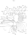
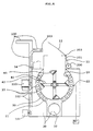
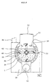
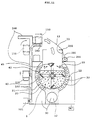
- the general fermenting and drying apparatus for food garbage comprises : a food garbage tank 10 in which an inlet part 11 having a cover 12 is installed at upper part, and an outlet 13 is installed at one side s lower part, in order to be able to discharge food garbage 1 outside after agitating, fermenting by ferment funguses and drying the food garbage 1 ; an agitator 40 including a rotation shaft 41 and plural agitating arms 42 in order to be able to agitate the food garbage 1 put in the food garbage tank 10; a heat - supplying part 30 including a burner 31, a combustion chamber 32, and a chimney 34 in order to be able to heat the food garbage tank 10 ; and an odor gas and steam - discharging outlet 19 installed at the upper part of the food garbage tank 10, or at the inlet part 11 thereof, in order to discharge the offensive odor and the steam
- the present invention comprises below - described structures, in addition to the above described structure of the general fermenting and drying apparatus for food garbage,
- a jacket 20 for heating the food garbage tank 10 through heat medium 21 embraces the food garbage tank 10, and plural combustion gas pipes 33 for heating the heat medium 21 are installed inside the jacket 20.
- the heat - supplying part 30 includes the combustion gas pipes 33 as parts of the combustion chamber 32, so that the jacket 20 is surrounded by the combustion chamber 32.
- General oil for heat medium is preferably used for the heat medium 21.
- the jacket 20 has a heat medium thermo - sensor 22 for sensing temperature of the heat medium 21 in the jacket 20.
- a temperature and time controller MC is installed, which is for controlling the burner 31 according to signal of the heat medium thermo - sensor 22 in order to maintain predetermined temperature of the heat medium 21 for predetermined time, during a fermenting step of the food garbage 1 and during a pyrolysis and drying step, of the food garbage 1, following the fermenting step.
- the heat medium thermo - sensor 22 is electrically connected to the temperature and time controller MC. And the temperature and time controller MC is electrically connected to the burner 31.
- the predetermined temperature of the heat medium 21 in the jacket 20 is, preferably, about 75°C, and, at this time, temperature of the food garbage 1 is about 60°C.
- the predetermined time is, preferably, about 5 hours.
- the predetermined temperature of the heat medium 21 in the jacket 20 becomes, preferably, about 140°C, and, at this time, temperature of the food garbage 1 becomes about 120°C, and the predetermined time is, preferably, about 12 to 20 hours according to the kinds of and the amount of the food garbage 1.
- An air intake 18 for continuously supplying the ferment funguses and oxygen in air to the food garbage tank 10 is installed at the upper part of the food garbage tank 10. It is possible to more accelerate the fermenting step s operation, by adding general ferment fungus to the food garbage 1.
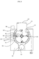
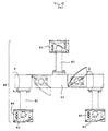
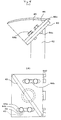
- the agitator 40 has first rectangular plates 43 each of which is, as one united boby, joined with one end of each of the agitating arms 42 and slopes to lengthwise direction of each of the agitating arms 42 ; and the agitator 40 has second rectangular plates 44 each of which is joined with each of the first plates 43 to overlap in correspondence with each of the first plates 43 ; and the agitator 40 has almost right - angled triangle - shaped third plates 45 each of which has sloping surface slightly curved outward and is joined with each of the second plates 44, to be perpendicular to, and in diagonal direction of, each of the second plates 44 ; in order that the food garbage 1 in the food garbage tank 10 can be efficiently mixed with air, particularly the ferment funguses and oxygen in air, during forward rotation of the agitator 40, and in order that the food garbage 1 in the food garbage tank 10 can be discharged outside through the outlet 13 during reverse rotation of the agitator 40.
- the second rectangular plate 44 for overlapping in correspondence with the first plate 43 is screwed to the first plate 43 in order to have possibility of being assembled or being disassembled.
- the screw joint is made, preferably, by both bolts 44a and female screws formed in the first plate 43.
- the second plate 44 has position - controlling grooves 44b for thereby controlling the position of the second plate 44 with respect to the first plate 43.
- One end of the second plate 44 is formed unevenly as an uneven part 44c for crushing the solid stuff contained in the food garbage 1.
- the agitating arm 42 preferably has a ring - shaped section and, as a whole, a form of a cylindrical pipe.
- the agitating arm 42 is screwed to the rotation shaft 41, in order to have possibility of being assembled or being disassembled.
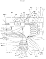
- An offensive odor gas - removing part 50 is connected to the odor gas and steam - discharging outlet 19 through a connection pipe 50 ⁇ 1 through which the odor gas and the steam pass, in order that the offensive odor gas can be removed through the offensive odor gas - removing part 50, by means of water - soluble odor gas , of the offensive odor gas(a: refer to FIG.10), being dissolved into steam - condensed water (that is, water condensed from steam)(c:refer to FIG.10) and then being discharged with the steam - condensed water (c), and by means of transmitting rest gas excluding the water - soluble odor gas to upper part 32a of the combustion chamber 32 for flammable odor gas of the rest gas to be burnt by combustion gas heat of the combustion chamber 32, according as the offensive odor gas (a) and the steam(b: refer to FIG.10) generated in the fermenting step of the food garbage 1 and the pyrolysis and drying step of the food garbage 1 are discharged through the odor gas
- the offensive odor gas - removing part 50 comprises :
- the water surface level of the steam - condensed water (c) in the steam - condensed water storage tank 58 is not lower than each of an upper end 51 ⁇ 2b ⁇ 1 of a lower part 51 ⁇ 2b of the first drainage pipe 51 ⁇ 2, an upper end 53 ⁇ 2b ⁇ 1 of a lower part 53 ⁇ 2b of the second drainage pipe 53 ⁇ 2 and an upper end 56b ⁇ 1 of a lower part 56b of the Y - shaped pipe 56, in order to prevent the odor gas (a), in gas state, from entering the steam - condensed water storage tank 58 through the first drainage pipe 51 ⁇ 2, the second drainage pipe 53 ⁇ 2 and the Y - shaped pipe 56 ;
- the first filter 51 and the second filter 53 are the general filters for filtering the dust.
- a valve 57 ⁇ 10 for controlling the transmission amount of the odor gas is installed around the other end 57 ⁇ 2 of the odor gas transmission pipe 57.
- the second filter 53 has a thermo - sensor 53s for making the agitator 40, the absorbing and transmitting fan 52 and the cooling device 55 (a cooling fan 55 ⁇ 1 in the air - cooling cooler) turn on, when temperature of the odor gas (a) and the steam (b) passing through the second filter 53 reaches predetermined degree (preferably about 70°C) or above ; and for making the agitator 40, the absorbing and transmitting fan 52 and the cooling device 55 (the cooling fan 55 ⁇ 1 in the air - cooling cooler) turn off, when temperature of the odor gas (a) and the steam (b) passing through the second filter 53 becomes below the predetermined degree, according as operation of the burner 31 is terminated as the fermenting step and the pyrolysis and drying step get completed by control of the temperature and time controller MC and additional controller.
- the combustion chamber 32 is maintained at about 600°C during the operation, and the upper part 32a of the combustion chamber 32 is preferably maintained at 250°C.
- An odor gas transmission outlet 32b is installed at the upper part 32a of the combustion chamber 32, and connected to one end 57 ⁇ 1 of the odor gas transmission pipe 57, in order that the odor gas (a) can be transmitted through the odor gas transmission pipe 57 to the upper part 32a.
- the cooling device 55 is a general cooling device, and preferably an air - cooling cooler having a cooling fan 55 ⁇ 1.
- its upper part is preferably maintained at about 65°C, and its lower part is preferably maintained at about 25°C.
- a food garbage lift vat 110 which is supported by a lift - supporting bar 100 and driven by a motor 101, a chain 102 and a chain gear 103, is installed, in order to lift food garbage and to put the food garbage in the food garbage tank 10 from outside.
- a cover 12 of the inlet part 11 of the food garbage tank 10 is driven by a motor 200, a chain 201 and a chain gear 202.
- 13 ⁇ 1 is an outlet - driving motor
- 40 ⁇ 1 is a chain gear
- 40 ⁇ 2 is a chain
- 40 ⁇ 3 is an agitator - driving motor
- 111 is a joining element.
- a jacket 20 for applying heat to the food garbage tank 10 through heat medium 21 is installed outside of the food garbage tank 10, and the plural combustion gas pipes 33 are installed inside the jacket 20. Accordingly, the heat medium 21 is heated by the heat supply from the combustion chamber 32 including the combustion gas pipes 33, and the food garbage 1 in the food garbage tank 10 is stably heated, so that the indirect heating from the heat source of the combustion chamber 32 is performed.
- the heat medium 21 is general heat - medium oil, the food garbage 1 in the food garbage tank 10 is stably heated at stable degree.
- the operation of the burner 31 is controlled by the temperature and time controller MC. Accordingly, during the fermenting step of the food garbage 1, the temperature of the heat medium 21 in the jacket 20 becomes the predetermined degree, preferably about 75°C, and at this time the temperature of the food garbage 1 is about 60°C. These temperatures are maintained for the predetermined time, preferably for about 5 hours.
- the temperature of the heat medium 21 becomes the predetermined degree, preferably about 140°C, and at this time the temperature of the food garbage 1 is about 120°C.
- These temperatures are maintained for the predetermined time, preferably for about 12 to 20 hours. Therefore, the preferable temperatures can be stably maintained by operation of the heat medium 21.
- the combustion gas pipes 33 are parts of the combustion chamber 32, so that the jacket 20 is surrounded by the combustion chamber 32. As a result, the surface area for transmitting the heat of the combustion chamber 32 to the heat medium 21 is maximized, and thereby the heat medium 21 is most efficiently heated.
- the air intake 18 is installed at the upper part of the food garbage tank 10, so that the ferment funguses and oxygen in air can be continuously supplied to the food garbage tank 10. Therefore, during the agitation and fermentation of the food garbage 1 in the food garbage tank 10, the fermentation effect is maximized by the oxygen and the ferment funguses continuously absorbed through the air intake 18, together with the ferment funguses previously existing in the food garbage 1. That is, the fermenting operation of the aerobic ferment funguses is maximized by the continuous supply of oxygen.
- the fermentation effect is able to be more enhanced.
- the absorption of air through the air intake 18 is continuously performed, according as air is discharged with the odor gas (a) and the steam (b) through the odor gas and steam - discharging outlet 19.
- the operation of the burner 31 is controlled by the temperature and time controller MC, according to the signal of the heat medium thermo - sensor 22. Accordingly, the temperature of the heat medium 21 in the jacket 20 becomes about 140°C, and at this time, the temperature of the food garbage 1 becomes about 120°C. These temperatures are stably maintained for about 12 to 20 hours. Accordingly, the food garbage 1 in the food garbage tank 10 is fully decomposed by heat, and simultaneously dried, so that the quantity decrease rate of the food garbage is maximized.
- the present invention has the drying operation and drying effect prominently faster than the conventional apparatus, so that the quantity decrease of the food garbage 1 and the composting of the food garbage 1 are high - speedly performed.
- the operation of the agitator 40 and its elements is performed as follows :
- the agitator 40 has the first rectangular plates 43, the second rectangular plates 44 and the almost right - angled triangle - shaped third plates 45.
- Each of the first rectangular plates 43 is, as one united body, joined with one end of each of the agitating arms 42, and slopes to lengthwise direction of each of the arms 42.
- Each of the second rectangular plates 44 is joined with each of the first plates 43 to overlap in correspondence with each of the first plates 43.
- Each of the almost right - angled triangle - shaped third plates 45 has sloping - surface which is slightly curved outward and joined with each of the second plates 44, to be perpendicular to, and in diagonal direction of, each of the second plates 44.
- the food garbage 1 in the food garbage tank 10 is efficiently mixed with air, particularly, the ferment funguses and oxygen in air, and efficently agitated, during the forward rotation of the agitator 40 (that is, the rotation of arrow P direction in FIGs.5 (a) and 5 (b), and FIG. 8).
- the reverse rotation of the agitator 40 that is, the rotation of the arrow Q direction in FIGs. 5 (a) and 5 (b), and FIG. 8
- the food garbage 1 in the food garbage tank 10 is discharged outside through the outlet 13.
- the food garbage 1 in the food garbage tank 10 is efficiently mixed with the ferment funguses and oxygen in air, and efficiently agitated and decomposed, mainly, by the operations of the first plates 43 and second plates 44 during the forward rotation of the agitator 40, so that the effect of the fermenting operation by the ferment funguses particularly the aerobic ferment funguses, and the effect of the pyrolysis and drying operation are maximized.
- the food garbage 1 in the food garbage tank 10 can be easily discharged outside through the outlet 13, mainly, by the operation of the third plates 45 during the reverse rotation of the agitator 40.
- the second rectangular plate 44 overlapped in correspondence with the first plate 43 is screwed to the first plate 43, the second plate 44 is easily assembled to, or easily disassembled from, the first plate 43 when its assembly or its disassembly is necessary for example the case of cleaning the agitator 40.
- the second plate 44 Since, in order to be able to control the position of the second plate 44 with respect to the first plate 43 the second plate 44 has plural position - controlling grooves 44b, the interval between an end part of the second plate 44 and the food garbage tank 10 can be properly controlled.
- the end of the second plate 44 is made in the form of the uneven part 44c having uneven end in order to cruch the solid stuff contained in the food garbage 1, the solid stuff, namely the bone groups of the cow or the chicken, can be crushed in a minimum size.
- the agitating arm 42 has a ring - shaped section, remainder of the food garbage 1 inserted in the agitating arms 42 does not exist. Since the agitating arms 42 are screwed to the rotation shaft 41, the agitating arms 42 can be easily disassembled and cleaned.
- the steam (b) is partially cooled by the temperature of the first filter 51 whose natural temperature is relatively low, namely near the normal temperature, when the odor gas (a) and the steam (b), whose temperatures are about 100°C at the time of their having been discharged from the connection pipe 50 ⁇ 1, pass through the inside 51a of the first filter 51. Accordingly the steam (b) becomes the steam - condensed water (c), and the steam - condensed water (c) flows down to the steam - condensed water storage tank 58 through the first drainage pipe 51 ⁇ 2.
- connection pipe 51 ⁇ 1 and the absorbing and transmitting fan 52 By means of the connection pipe 51 ⁇ 1 and the absorbing and transmitting fan 52, the odor gas (a) and the steam (b) from the first filter 51 are absorbed to the absorbing and transmitting fan 52 through the connection pipe 51 ⁇ 1, and then the odor gas (a) and the steam (b) are transmitted to the second filter 53 through the connection pipe 52 ⁇ 1.
- the steam (b) is partially cooled by the temperature of the second filter 53 whose natural temperature is relatively low, namely near the normal temperature, when the odor gas (a) and the steam (b), whose temperature are about 80°C at the time of their having been transmitted from the connection pipe 52 ⁇ 1, pass through the inside 53a of the second filter 53. Accordingly, the steam (b) becomes the steam - condensed water (c), and the steam - condensed water (c) flows down to the steam - condensed water storage tank 58 through the second drainage pipe 53 ⁇ 2.
- the steam (b) is condensed into the steam - condensed water (c) from at the inlet 54 ⁇ 1, namely the upper part, of the condensing pipe 54, whose temperature is about 65°C, and more condensed into the steam - condensed water (c) at the lower part, of the condensing pipe 54, whose temperature is about 25°C, by the condensing pipe 54 and the cooling device 55. And then the steam - condensed water (c) flows down.
- the water - soluble odor gas of the odor gas (a), for example, ammonia(NH 3 ) gas is dissolved in the steam - condensed water (c), and then the water - soluble odor gas is stored in the steam - condensed water storage tank 58 with the steam - condensed water (c), and thereafter discharged. Accordingly, the offensive odor is reduced.
- the odor gas (a) is not mixed with the steam (b) as below - described, the flammable odor gas of the offensive odor gas (a) can be completely burnt.
- the Y - shaped pipe 56 has the operation as follows :
- the upper outlet 56 ⁇ 2 of the Y - shaped pipe 56 is connected to the other end 57 ⁇ 2 of the odor gas transmission pipe 57.
- the upper inlet 56 ⁇ 1 of the Y - shaped pipe 56 is connected to the outlet 54 ⁇ 2 of the condensing pipe 54 in order to make the steam - condensed water (c), of the odor gas (a) and the steam - condensed water (c) having been transmitted from the outlet 54 ⁇ 2 of the condensing pipe (54), flow down to the steam - condensed water storage tank 58.
- the lower outlet 56 ⁇ 3 of the Y ⁇ shaped pipe 56 is connected to the steam - condensed water storage tank 58. Accordingly, the steam - condensed water (c) flowing down from the condensing pipe 54 flows down to the steam - condensed water storage tank 58 through the Y - shaped pipe 56.
- the water surface level of the steam - condensed water (c) in the steam - condensed water storage tank 58 is not lower than each of the upper end 51 ⁇ 2b ⁇ 1 of the lower part 51 ⁇ 2b of the first drainage pipe 51 ⁇ 2, the upper end 53 ⁇ 2b ⁇ 1 of the lower part 53 ⁇ 2b of the second drainage pipe 53 ⁇ 2 and the upper end 56b ⁇ 1 of the lower part 56b of the Y - shaped pipe 56.
- the steam - condensed water (c) can fill up the lower part 51 ⁇ 2b of the first drainage pipe 51 ⁇ 2, the lower part 53 ⁇ 2b of the second drainage pipe 53 ⁇ 2 and the lower part 56b of the Y - shaped pipe 56, the lower part 51 ⁇ 2b of the first drainage pipe 51 ⁇ 2, the lower part 53 ⁇ 2b of the second drainage pipe 53 ⁇ 2 and the lower part 56b of the Y - shaped pipe 56 are placed lower than an upper end 59a of the steam - condensed water - discharging pipe 59.
- the odor gas (a) making contact with the water surface, of the steam - condensed water (c), which is not lower than the upper ends 51 ⁇ 2b ⁇ 1, 53 ⁇ 2b ⁇ 1 and 56b ⁇ 1 of the lower parts 51 ⁇ 2b, 53 ⁇ 2b, 56b can not flow in the direction to the steam - condensed water (c) in the steam - condensed water storage tank 58.
- the odor gas (a) having been transmitted through the upper inlet 56 ⁇ 1 of the Y - shaped pipe 56 from the condensing pipe 54, is transmitted to the upper part 32a of the combustion chamber 32 through the upper outlet 56 ⁇ 2 of the Y - shaped pipe 56, the odor gas transmission pipe 57 and the odor gas transmission outlet 32b, so that the odor gas (a) is burnt by the combustion gas heat.
- the water surface of the steam - condensed water (c) in the steam - condensed water storage tank 58 maintains the level which is not lower than the upper end 59a of the steam - condensed water - discharging pipe 59. Therefore, the operation that the steam - condensed water (c) fills up the lower parts 51 ⁇ 2b, 53 ⁇ 2b and 56b is performed .
- the odor gas (a) and the steam (b) are discharged through the odor gas and steam - discharging outlet 19
- the water - soluble odor gas of the odor gas (a) is dissolved into the steam - condensed water (c) and discharged with the steam - condensed water (c), and the rest odor gas excluding the water - soluble odor gas is transmitted to the upper part 32a of the combustion chamber 32, by the above - described operation of the structure of the offensive odor gas - removing part 50.
- the flammable odor gas of the rest odor gas is burnt by the combustion gas heat of the combustion chamber 32, so that the offensive odor is removed.
- the flammable odor gas transmitted to the upper part 32a of the combustion chamber 32 has the state of not being mixed with the steam (b). Accordingly, the flammable odor gas is completely burnt by combustion in state of not being mixed with the steam (b), and as a result the offensive odor gas is removed.
- the present invention can prevent heat efficiency of the combustion chamber 32 from descending due to the combustion chamber 32 s temperature descent caused by the steam, and prevent the inside of the combustion chamber 32 from rusting due to the steam.
- thermo - sensor 53s makes the agitator 40, the absorbing and transmitting fan 52 and the cooling device 55 (a cooling fan 55 ⁇ 1 in the air - cooling cooler) turn on, so that the fermenting step and the pyrolysis and drying step proceed.
- thermo - sensor 53s makes the agitator 40, the absorbing and transmitting fan 52 and the cooling device 55 (the cooling fan 55 ⁇ 1 in the air - cooling cooler) turn off. Accordingly, the fermenting step and the pyrolysis and drying step terminate. As a result, an automation of the proceeding and terminating these steps is possible by the present invention.
- a cover 12 of an inlet part 11 of the food garbage tank 10 is driven by a motor 200, a chain 201 and a chain gear 202, the cover 12 which is stained with dirty food garbage can be easily opened and closed without directly handling it by hand, so that the work performance efficiency is enhanced, and the food garbage is easily put in the food garbage tank 10.
- the present invention has following effects.
- the present invention since the present invention performs the fermenting operation by utilizing the ferment funguses in the food garbage itself and in air, and oxygen in air without using an additional ferment fungus, the present invention has no trouble in keeping, managing or adding the additional ferment fungus.
- the present invention agitates and decomposes the food garbage with the first plates, the second plates and the third plates of the agitator, and crushes the food garbage by the uneven parts of the second plates, and maintains stable temperature for the fermentation, and stable temperature for the pyrolysis and drying by means of the indirect heating by the heat - medium, effects of the fermentation, and the pyrolysis and drying can be maximized.
- the fermenting step and the pyrolysis and drying step for composting of the food garbage can be high - speedly completed for a minimum time.
- the present invention since the present invention does not need addition such as the ferment fungus and moisture content percentage - controlling stuff, the present invention can maximize quantity - decreasing effect of the food garbage.
- the present invention can easily remove, by simple structure, the offensive odor gas generated during the fermenting step and the pyrolysis and drying step, by means of the water - soluble odor gas being dissolved into the steam - condensed water and being discharged with the steam - condensed water, and by means of the flammable odor gas , of the offensive odor gas, being burnt by the combustion gas heat.
- the steam, of the offensive odor gas and the steam generated in the fermenting step of the food garbage and the pyrolysis and drying step of the food garbage gets condensed into the steam - condensed water, and discharged, and the water - soluble odor gas of the odor gas is dissolved into the steam - condensed water, and discharged with the steam - condensed water, the flammable odor gas of the state of not being mixed with the steam is burnt by combustion gas heat at the upper part of the combustion chamber, so that the flammable odor gas is completely burnt.
- heat efficiency of the combustion chamber can be prevented from descending due to the combustion chamber s temperature descent caused by the steam ; and the inside of the combustion chamber can be prevented from rusting due to the steam.
Landscapes
- Engineering & Computer Science (AREA)
- Chemical & Material Sciences (AREA)
- Organic Chemistry (AREA)
- Life Sciences & Earth Sciences (AREA)
- Microbiology (AREA)
- Mechanical Engineering (AREA)
- Chemical Kinetics & Catalysis (AREA)
- General Chemical & Material Sciences (AREA)
- Health & Medical Sciences (AREA)
- Molecular Biology (AREA)
- Biochemistry (AREA)
- General Engineering & Computer Science (AREA)
- Biotechnology (AREA)
- Sustainable Development (AREA)
- Combustion & Propulsion (AREA)
- Manufacturing & Machinery (AREA)
- Environmental & Geological Engineering (AREA)
- Processing Of Solid Wastes (AREA)
Applications Claiming Priority (2)
| Application Number | Priority Date | Filing Date | Title |
|---|---|---|---|
| KR1019970005433A KR100205918B1 (ko) | 1997-02-22 | 1997-02-22 | 음식물쓰레기 고속 발효 건조 장치 |
| KR9705433 | 1997-02-22 |
Publications (2)
| Publication Number | Publication Date |
|---|---|
| EP0860407A2 true EP0860407A2 (de) | 1998-08-26 |
| EP0860407A3 EP0860407A3 (de) | 1999-06-16 |
Family
ID=19497696
Family Applications (1)
| Application Number | Title | Priority Date | Filing Date |
|---|---|---|---|
| EP97109135A Ceased EP0860407A3 (de) | 1997-02-22 | 1997-06-05 | Hochgeschwindigkeitsfermentierung- und Trockenapparat von Lebensmittelabfall |
Country Status (2)
| Country | Link |
|---|---|
| EP (1) | EP0860407A3 (de) |
| KR (1) | KR100205918B1 (de) |
Cited By (10)
| Publication number | Priority date | Publication date | Assignee | Title |
|---|---|---|---|---|
| EP0924488A1 (de) * | 1997-12-16 | 1999-06-23 | Paloma Industries, Ltd. | Abfallbeseitiger |
| WO2003057381A1 (en) * | 2002-01-12 | 2003-07-17 | Chun-Il Koh | Decomposition device of organic waste and automatic cleaning system thereof |
| WO2013163168A1 (en) * | 2012-04-26 | 2013-10-31 | The Procter & Gamble Company | Composting appliance |
| CN103521503A (zh) * | 2013-10-24 | 2014-01-22 | 江苏维尔利环保科技股份有限公司 | 用于餐厨垃圾粗浆料的机械生化反应装置 |
| WO2015156742A3 (en) * | 2014-04-07 | 2015-12-03 | Brinox, D.O.O. | Horizontal paddle dryer |
| CN108728350A (zh) * | 2018-07-20 | 2018-11-02 | 杭州洁洁环保科技有限公司 | 负压恒温干燥设备 |
| CN110756546A (zh) * | 2018-07-10 | 2020-02-07 | 雅高环保(香港)有限公司 | 用于分解食品废物的装置和方法 |
| CN115728450A (zh) * | 2022-11-14 | 2023-03-03 | 北京京仪大气环保科技有限公司 | 移动温室气体检测车 |
| CN119241294A (zh) * | 2024-10-28 | 2025-01-03 | 潮州安芮洁环保科技有限公司 | 一种生物肥料垃圾发酵筒 |
| IT202300024621A1 (it) * | 2023-11-21 | 2025-05-21 | Comas Costruzioni Macch Speciali S P A | Miscelatore e metodo per la realizzazione di un impasto a base vegetale. |
Families Citing this family (21)
| Publication number | Priority date | Publication date | Assignee | Title |
|---|---|---|---|---|
| KR100231961B1 (ko) * | 1997-07-11 | 1999-12-01 | 이소영 | 고속단일공법에 의한 저온 자연발효 수산물 분말제품 |
| KR19990078874A (ko) * | 1999-08-16 | 1999-11-05 | 김영숙 | 음식물쓰레기 처리장치 |
| KR20010070806A (ko) * | 2001-06-08 | 2001-07-27 | 이종수 | 음식물 쓰레기 처리장치 및 방법 |
| KR100488497B1 (ko) * | 2001-11-07 | 2005-05-16 | 주식회사 썬업미디어 | 음식물 쓰레기 처리기 |
| KR100477074B1 (ko) * | 2002-05-24 | 2005-03-17 | 고천일 | 유기성 폐기물 발효분해장치 |
| KR100844915B1 (ko) | 2004-11-23 | 2008-07-09 | 이지엠테크 주식회사 | 제 처리의 병행 처리가 가능한 음식물 쓰레기의 발효분해 소멸화 처리장치 |
| KR100832785B1 (ko) * | 2007-04-20 | 2008-05-27 | 고천일 | 음식물쓰레기 소멸처리시스템장치 |
| KR101102586B1 (ko) * | 2009-03-16 | 2012-01-04 | 이현주 | 음식물 쓰레기 처리 장치 |
| KR100990164B1 (ko) | 2009-11-11 | 2010-10-29 | 이현주 | 음식물 쓰레기 처리장치 |
| KR101283718B1 (ko) * | 2011-07-27 | 2013-07-08 | 장성산업 주식회사 | 음식물 처리기용 탈취장치 |
| KR101650097B1 (ko) * | 2013-12-03 | 2016-09-20 | 주식회사 제이에스엠 | 건조장치 |
| CN104031665A (zh) * | 2014-06-23 | 2014-09-10 | 北京建筑材料科学研究总院有限公司 | 一种可燃废物定向热解方法 |
| KR101733234B1 (ko) * | 2016-05-26 | 2017-05-08 | 엔디티엔지니어링(주) | 건조효율이 개선된 폐열을 활용한 음식물 건조장치 |
| WO2018079958A1 (ko) | 2016-10-25 | 2018-05-03 | 엔디티엔지니어링(주) | 건조효율이 개선된 폐열을 활용한 음식물 건조장치 |
| KR101984882B1 (ko) * | 2017-09-15 | 2019-05-31 | 한국에너지기술연구원 | 발효 및 건조 복합 공정을 통한 유기성 폐기물 처리 장치 및 방법 |
| CN108168246B (zh) * | 2017-12-08 | 2020-07-24 | 佛山市顺德区仕麦电器科技有限公司 | 一种循环式黄豆均匀烘干装置 |
| KR102197940B1 (ko) * | 2019-01-18 | 2021-01-04 | 대명전자통신(주) | 음식물 냄새 제거장치 |
| KR102342186B1 (ko) * | 2019-10-31 | 2021-12-22 | 코스탈 주식회사 | 음식물 쓰레기 처리장치 |
| CN112611212B (zh) * | 2020-12-08 | 2022-04-26 | 中农新科(苏州)有机循环研究院有限公司 | 一种餐厨垃圾快速生物干化反应器 |
| KR102563017B1 (ko) * | 2021-11-30 | 2023-08-03 | 안진우 | 음식물 쓰레기 처리장치 |
| CN118274600B (zh) * | 2024-06-03 | 2024-07-26 | 潍坊易北特生物科技有限公司 | 一种益生菌粉体连续干燥装置 |
Family Cites Families (2)
| Publication number | Priority date | Publication date | Assignee | Title |
|---|---|---|---|---|
| GB2286825B (en) * | 1994-02-15 | 1998-02-11 | Matsushita Electric Works Ltd | Garbage treating apparatus |
| KR0149616B1 (ko) * | 1994-08-19 | 1998-08-17 | 가나이 쯔또무 | 고형유기폐기물의 처리장치 |
-
1997
- 1997-02-22 KR KR1019970005433A patent/KR100205918B1/ko not_active Expired - Fee Related
- 1997-06-05 EP EP97109135A patent/EP0860407A3/de not_active Ceased
Cited By (15)
| Publication number | Priority date | Publication date | Assignee | Title |
|---|---|---|---|---|
| EP0924488A1 (de) * | 1997-12-16 | 1999-06-23 | Paloma Industries, Ltd. | Abfallbeseitiger |
| US6076271A (en) * | 1997-12-16 | 2000-06-20 | Paloma Industries, Ltd. | Garbage disposer |
| WO2003057381A1 (en) * | 2002-01-12 | 2003-07-17 | Chun-Il Koh | Decomposition device of organic waste and automatic cleaning system thereof |
| US7604986B2 (en) * | 2002-01-12 | 2009-10-20 | Chun-Il Koh | Decomposition device of organic waste and automatic cleaning system thereof |
| WO2013163168A1 (en) * | 2012-04-26 | 2013-10-31 | The Procter & Gamble Company | Composting appliance |
| CN103521503A (zh) * | 2013-10-24 | 2014-01-22 | 江苏维尔利环保科技股份有限公司 | 用于餐厨垃圾粗浆料的机械生化反应装置 |
| WO2015156742A3 (en) * | 2014-04-07 | 2015-12-03 | Brinox, D.O.O. | Horizontal paddle dryer |
| CN106461329A (zh) * | 2014-04-07 | 2017-02-22 | Brinox公司 | 卧式桨叶干燥机 |
| US10724795B2 (en) | 2014-04-07 | 2020-07-28 | Brinox, D.O.O. | Horizontal paddle dryer |
| CN110756546A (zh) * | 2018-07-10 | 2020-02-07 | 雅高环保(香港)有限公司 | 用于分解食品废物的装置和方法 |
| CN108728350A (zh) * | 2018-07-20 | 2018-11-02 | 杭州洁洁环保科技有限公司 | 负压恒温干燥设备 |
| CN115728450A (zh) * | 2022-11-14 | 2023-03-03 | 北京京仪大气环保科技有限公司 | 移动温室气体检测车 |
| CN115728450B (zh) * | 2022-11-14 | 2024-12-03 | 北京京仪大气环保科技有限公司 | 移动温室气体检测车 |
| IT202300024621A1 (it) * | 2023-11-21 | 2025-05-21 | Comas Costruzioni Macch Speciali S P A | Miscelatore e metodo per la realizzazione di un impasto a base vegetale. |
| CN119241294A (zh) * | 2024-10-28 | 2025-01-03 | 潮州安芮洁环保科技有限公司 | 一种生物肥料垃圾发酵筒 |
Also Published As
| Publication number | Publication date |
|---|---|
| KR100205918B1 (ko) | 1999-07-01 |
| EP0860407A3 (de) | 1999-06-16 |
| KR970020232A (ko) | 1997-05-28 |
Similar Documents
| Publication | Publication Date | Title |
|---|---|---|
| EP0860407A2 (de) | Hochgeschwindigkeitsfermentierung- und Trockenapparat von Lebensmittelabfall | |
| CN102083556B (zh) | 食物垃圾处理机 | |
| US5440823A (en) | Process and apparatus for efficiently drying wet-milled corn germ and for processing other materials | |
| CN107410834A (zh) | 一种基于蒸煮泡于一体的食品加工设备 | |
| KR101659814B1 (ko) | 디스크 건조기 | |
| KR0137056Y1 (ko) | 발효사료제조장치 | |
| KR100511196B1 (ko) | 슬러지 건조장치 | |
| CN218380277U (zh) | 一种石油助剂生产用干燥装置 | |
| KR100282014B1 (ko) | 유기성 폐기물 및 농축산 부산물을 이용한 퇴비화 및 사료화를위한 혼합 건조 장치. | |
| KR200214056Y1 (ko) | 음식물쓰레기의고속진공발효건조기 | |
| KR20020041753A (ko) | 음식쓰레기 처리장치 | |
| JPH08136129A (ja) | 含水物乾燥処理装置 | |
| CN108741198A (zh) | 一种畜牧养殖用饲料加工装置 | |
| CN212339747U (zh) | 干燥机 | |
| CN214142275U (zh) | 一种一体式高效节能蒸酒装置 | |
| WO2005099920A1 (en) | Food waste treating system and control method therefor | |
| KR200368277Y1 (ko) | 음식물 쓰레기의 고속진공 발효건조기 | |
| KR100567409B1 (ko) | 슬러지 건조장치 및 건조 방법 | |
| CN213395325U (zh) | 一种具有高效散热热解焚烧炉 | |
| CN217297654U (zh) | 一种污泥低温除湿干化装置 | |
| CN223921372U (zh) | 一种米糠油快速脱脂冷却装置 | |
| JPH08271148A (ja) | 厨芥処理設備 | |
| KR200251336Y1 (ko) | 음식물 쓰레기의 고속진공 발효건조기 | |
| CN221028455U (zh) | 一种生物发酵用温控装置 | |
| CN223352400U (zh) | 一种石英砂浸酸提纯装置 |
Legal Events
| Date | Code | Title | Description |
|---|---|---|---|
| PUAI | Public reference made under article 153(3) epc to a published international application that has entered the european phase |
Free format text: ORIGINAL CODE: 0009012 |
|
| AK | Designated contracting states |
Kind code of ref document: A2 Designated state(s): AT BE CH DE DK ES FR GB GR IT LI NL |
|
| AX | Request for extension of the european patent |
Free format text: AL;LT;LV;RO;SI |
|
| PUAL | Search report despatched |
Free format text: ORIGINAL CODE: 0009013 |
|
| AK | Designated contracting states |
Kind code of ref document: A3 Designated state(s): AT BE CH DE DK ES FI FR GB GR IE IT LI LU MC NL PT SE |
|
| AX | Request for extension of the european patent |
Free format text: AL;LT;LV;RO;SI |
|
| RIC1 | Information provided on ipc code assigned before grant |
Free format text: 6C 05F 9/02 A, 6C 05F 17/02 B, 6C 05F 17/00 B |
|
| 17P | Request for examination filed |
Effective date: 19990702 |
|
| 17Q | First examination report despatched |
Effective date: 19990923 |
|
| AKX | Designation fees paid |
Free format text: AT BE CH DE DK ES FR GB GR IT LI NL |
|
| GRAG | Despatch of communication of intention to grant |
Free format text: ORIGINAL CODE: EPIDOS AGRA |
|
| STAA | Information on the status of an ep patent application or granted ep patent |
Free format text: STATUS: THE APPLICATION HAS BEEN REFUSED |
|
| 18R | Application refused |
Effective date: 20020223 |