EP0860610A1 - Machine à engrenages internes, en particulier pompe à engrenages internes - Google Patents
Machine à engrenages internes, en particulier pompe à engrenages internes Download PDFInfo
- Publication number
- EP0860610A1 EP0860610A1 EP98102767A EP98102767A EP0860610A1 EP 0860610 A1 EP0860610 A1 EP 0860610A1 EP 98102767 A EP98102767 A EP 98102767A EP 98102767 A EP98102767 A EP 98102767A EP 0860610 A1 EP0860610 A1 EP 0860610A1
- Authority
- EP
- European Patent Office
- Prior art keywords
- filler
- spring
- internal gear
- housing
- machine according
- Prior art date
- Legal status (The legal status is an assumption and is not a legal conclusion. Google has not performed a legal analysis and makes no representation as to the accuracy of the status listed.)
- Ceased
Links
- 239000000945 filler Substances 0.000 claims abstract description 60
- 238000007789 sealing Methods 0.000 claims abstract description 23
- 238000005192 partition Methods 0.000 claims description 4
- 239000007788 liquid Substances 0.000 claims 1
- 230000000284 resting effect Effects 0.000 claims 1
- 238000004519 manufacturing process Methods 0.000 description 2
- 230000004308 accommodation Effects 0.000 description 1
- 238000006073 displacement reaction Methods 0.000 description 1
- 239000000463 material Substances 0.000 description 1
Images

Classifications
-
- F—MECHANICAL ENGINEERING; LIGHTING; HEATING; WEAPONS; BLASTING
- F04—POSITIVE - DISPLACEMENT MACHINES FOR LIQUIDS; PUMPS FOR LIQUIDS OR ELASTIC FLUIDS
- F04C—ROTARY-PISTON, OR OSCILLATING-PISTON, POSITIVE-DISPLACEMENT MACHINES FOR LIQUIDS; ROTARY-PISTON, OR OSCILLATING-PISTON, POSITIVE-DISPLACEMENT PUMPS
- F04C2/00—Rotary-piston machines or pumps
- F04C2/08—Rotary-piston machines or pumps of intermeshing-engagement type, i.e. with engagement of co-operating members similar to that of toothed gearing
- F04C2/10—Rotary-piston machines or pumps of intermeshing-engagement type, i.e. with engagement of co-operating members similar to that of toothed gearing of internal-axis type with the outer member having more teeth or tooth-equivalents, e.g. rollers, than the inner member
- F04C2/101—Rotary-piston machines or pumps of intermeshing-engagement type, i.e. with engagement of co-operating members similar to that of toothed gearing of internal-axis type with the outer member having more teeth or tooth-equivalents, e.g. rollers, than the inner member with a crescent-shaped filler element, located between the inner and outer intermeshing members
-
- Y—GENERAL TAGGING OF NEW TECHNOLOGICAL DEVELOPMENTS; GENERAL TAGGING OF CROSS-SECTIONAL TECHNOLOGIES SPANNING OVER SEVERAL SECTIONS OF THE IPC; TECHNICAL SUBJECTS COVERED BY FORMER USPC CROSS-REFERENCE ART COLLECTIONS [XRACs] AND DIGESTS
- Y10—TECHNICAL SUBJECTS COVERED BY FORMER USPC
- Y10T—TECHNICAL SUBJECTS COVERED BY FORMER US CLASSIFICATION
- Y10T74/00—Machine element or mechanism
- Y10T74/19—Gearing
- Y10T74/19642—Directly cooperating gears
- Y10T74/19647—Parallel axes or shafts
Definitions
- the machine concerns an internal gear machine, in particular internal gear pump, with the features according to Preamble of claim 1.
- the housed in the interface space of the filler Leaf spring is inevitably very small and must therefore be included high precision manufactured and built to a reasonably exactly predetermined spring force on the Exercise sealing roller. This is complex and therefore expensive and depending on the coincidence of the tolerance dimensions of the Leaf spring and the interface space can still be a Fluctuation of the spring force exerted on the sealing roller cannot be avoided.
- the object of the invention is therefore a To create internal gear machine of the type described, the with regard to the spring arrangement and training Actuation of the respectively assigned sealing roller is simpler and therefore less expensive and also a simple fine-tuning of the spring load allowed.
- the Filler parts with respect to one containing the pinion axis Radial plane shaped symmetrically and accordingly are symmetrically arranged partitions spring-loaded sealing rollers added. To match that also symmetrically arranged free spaces for accommodation the spring ends.
- the filler pin is either its bearing bore correspondingly cylindrical or has a cheaper design essentially one square cross-section, chamfered on the edges is. The chamfers result in the rotatable bearing in the assigned housing bore.
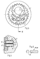
- the running group shown in Fig. 1 Internal gear pump according to the invention consists essentially from a ring gear 1, one meshing with the ring gear 1 Pinion 2 and one in the space between the ring gear 1st and the pinion 2 arranged filler, the whole with 3 is designated.
- the ring gear 1 is conventional stored in a circumferential housing 4, the axial Housing parts sealing on the axial surfaces of ring gear 1, Pinion 2 and filler 3 are in contact. Because the corresponding Structure is well known, no one is needed here single detailed explanation thereof (see. DE-A 43 36 966).
- the filler 3 is approximated by a Circumferential dividing surface in two Filler pieces 30, 31 divided, of which the radially inner Filler piece 30 on the tooth tips of the pinion 2 and that radially outer filler part 31 on the tooth tips of the Ring gear 1 is applied.
- the filler 3 and thus its Filler piece parts 30, 31 are symmetrical to the axis of the pinion 2 containing radial plane A and form symmetrically arranged, identically designed Partition space 32.
- the filler parts 30, 31 In the area of each part space 32 the filler parts 30, 31 each have an inclined surface 34, 35, which are wedge-shaped to each other and to the Indicate plane of symmetry A.
- a sealing roller 36 On the inclined surfaces 34, 35 is in each case a sealing roller 36, which by a hairpin-shaped spring 37 on the inclined surfaces 34, 35 is pressed.
- the hairpin-shaped spring 37 consists of a correspondingly curved strips of flat material. Your Spring legs are approximately axially parallel to the axis of the Pinion 2 and the ring gear 1 directed and lie on the one hand on the sealing roller 36, on the other hand on one Shoulder 38 of the radially outer filler part 31. The Shoulder 38 thus forms a for the spring 37 Support surface in the interface area 32. Das hairpin-shaped curved end 39 of the spring 37 is in one Free space 40 of the housing 4 added (Fig. 2).
- Free space 40 is one in the exemplary embodiment shown Bore, the cross section of which is sufficiently large to on the one hand to be able to take up the curved spring end freely, on the other hand, slight movements of the filler 3 without the spring contacting the bore wall allow.
- the filler parts 30, 31 are pivotable and radial slidably supported by a filler pin 5.
- a filler pin 5 is with a cylindrical end in one assigned bearing bore of the housing 4 rotatable recorded and points at its facing the filler Face a rib 51 flat on both sides, the in a corresponding groove on the axial flanks of the Filler piece parts 30, 31 engages (cf. DE-A 43 36 966).
- the storage of the filler pin 5 in the housing 4 results in the pivotability, the inclusion of the flat rib 51 of the filler pin 5 in the corresponding groove Filler pieces 30, 31 the limited radial Movability of the filler parts.
- FIGS. 3 to 5 differs from the previously described only in that the Filler piece parts 30 ', 31' not on a common one Filler pen are stored, but each separately its own filler pin 52, 53.
- the two Filler pins 52, 53 have one substantially square cross section, the corners of which are chamfered 54 are rounded, so that strictly speaking an octagonal Cross section is present (Fig. 5).
- Both filler pins 52, 53 are rotatable in bores 55, 56 of the housing 4 ' added (Fig. 4). With the filler 3 ' facing end they protrude into corresponding grooves 51 'of the two filler parts and keep them radially displaceable analogous to the design in the exemplary embodiment according to 1 and 2.
Landscapes
- Engineering & Computer Science (AREA)
- Mechanical Engineering (AREA)
- General Engineering & Computer Science (AREA)
- Rotary Pumps (AREA)
Applications Claiming Priority (2)
| Application Number | Priority Date | Filing Date | Title |
|---|---|---|---|
| DE19706639 | 1997-02-20 | ||
| DE19706639A DE19706639C2 (de) | 1997-02-20 | 1997-02-20 | Innenzahnradmaschine, insbesondere Innenzahnradpumpe |
Publications (1)
| Publication Number | Publication Date |
|---|---|
| EP0860610A1 true EP0860610A1 (fr) | 1998-08-26 |
Family
ID=7820885
Family Applications (1)
| Application Number | Title | Priority Date | Filing Date |
|---|---|---|---|
| EP98102767A Ceased EP0860610A1 (fr) | 1997-02-20 | 1998-02-18 | Machine à engrenages internes, en particulier pompe à engrenages internes |
Country Status (3)
| Country | Link |
|---|---|
| US (1) | US5951274A (fr) |
| EP (1) | EP0860610A1 (fr) |
| DE (2) | DE19706639C2 (fr) |
Families Citing this family (4)
| Publication number | Priority date | Publication date | Assignee | Title |
|---|---|---|---|---|
| JP4555756B2 (ja) * | 2005-09-13 | 2010-10-06 | 株式会社ケーヒン | 絞り弁制御装置 |
| DE102012214356A1 (de) * | 2012-08-13 | 2014-02-13 | Robert Bosch Gmbh | Innenzahnradpumpe |
| US11506200B1 (en) | 2020-02-27 | 2022-11-22 | Parker-Hannifin Corporation | Hydraulic gear pump with radial pressure compensator |
| CN113236554B (zh) * | 2021-06-04 | 2022-06-21 | 中国人民解放军海军工程大学 | 一种可双向旋转的渐开线齿廓内啮合齿轮泵 |
Citations (1)
| Publication number | Priority date | Publication date | Assignee | Title |
|---|---|---|---|---|
| DE4336966A1 (de) * | 1993-10-29 | 1995-05-04 | Otto Eckerle | Innenzahnradmaschine |
Family Cites Families (3)
| Publication number | Priority date | Publication date | Assignee | Title |
|---|---|---|---|---|
| DE1653818A1 (de) * | 1967-02-28 | 1971-06-09 | Daimler Benz Ag | Innenverzahnte Zahnradpumpe,insbesondere fuer die Druckmittelversorgung von selbsttaetig schaltenden Kraftfahrzeuggetrieben |
| DE2942417A1 (de) * | 1979-10-19 | 1981-05-14 | Otto Eckerle GmbH & Co KG, 7502 Malsch | Innenzahnradmaschine |
| DE2954546C2 (fr) * | 1979-10-19 | 1989-07-06 | Otto Eckerle Gmbh & Co Kg, 7502 Malsch, De |
-
1997
- 1997-02-20 DE DE19706639A patent/DE19706639C2/de not_active Expired - Fee Related
- 1997-08-29 DE DE29715534U patent/DE29715534U1/de not_active Expired - Lifetime
-
1998
- 1998-02-18 EP EP98102767A patent/EP0860610A1/fr not_active Ceased
- 1998-02-19 US US09/026,081 patent/US5951274A/en not_active Expired - Fee Related
Patent Citations (1)
| Publication number | Priority date | Publication date | Assignee | Title |
|---|---|---|---|---|
| DE4336966A1 (de) * | 1993-10-29 | 1995-05-04 | Otto Eckerle | Innenzahnradmaschine |
Also Published As
| Publication number | Publication date |
|---|---|
| DE29715534U1 (de) | 1997-11-06 |
| DE19706639A1 (de) | 1998-08-27 |
| DE19706639C2 (de) | 1998-12-24 |
| US5951274A (en) | 1999-09-14 |
Similar Documents
| Publication | Publication Date | Title |
|---|---|---|
| DE3830746C2 (fr) | ||
| DE3608984A1 (de) | Staubdichter schrank, besonders fuer elektrische anlagen | |
| DE3841629A1 (de) | Rollenlagerung | |
| DE102011087424A1 (de) | Aussenzahnradpumpe | |
| DE3709673A1 (de) | Waelzkoerperlager mit einem zweiteiligen kaefig | |
| DE2645992C2 (fr) | ||
| DE4125730A1 (de) | Rollenlager mit durch verformen gebildeten rollenhalterungsvorspruengen | |
| DE19706639C2 (de) | Innenzahnradmaschine, insbesondere Innenzahnradpumpe | |
| DE2258712B2 (de) | Abdichtung einer Kreiskolbenmaschine | |
| DE3040038C2 (de) | Mehrscheiben-Isolierglaseinheit mit in den Eckwinkeln des Distanzrahmens befindlichen Gaseinfüllbohrungen | |
| DE3544857C2 (de) | Innenzahnradmaschine | |
| DE2929618C2 (de) | Vibrationshandschleifmaschine | |
| DE3901362A1 (de) | Gleitringdichtung zur abdichtung eines gasfoermigen mediums | |
| DE69616929T2 (de) | Distanzstück für Wälzkörper eines Lagers oder Rollenlager ohne Käfig | |
| DE3023733C2 (de) | Schließzylinder | |
| DE2937412C2 (de) | Kolbenanordnung | |
| DE202024104602U1 (de) | Griff und elektrische Zahnbürste | |
| DE2954546C2 (fr) | ||
| DE2408743A1 (de) | Traggehaeuse fuer elektromagneten | |
| DE2604969C2 (fr) | ||
| DE2523000A1 (de) | Fahrzeugbremsbetaetigungsvorrichtung mit einem spreizkeil | |
| DE10104621B4 (de) | Axialfeldabdichtung einer Zahnradmaschine | |
| DE2608647C3 (de) | Abdichtung für kolbenartige hydrostatische Stützelemente einer Durchbiegungseinstellwalze | |
| DE2649523C3 (de) | Lösbare Verbindung zweier Teile eines Gestells | |
| DE1553221C (de) | Drehkolbenpumpe |
Legal Events
| Date | Code | Title | Description |
|---|---|---|---|
| PUAI | Public reference made under article 153(3) epc to a published international application that has entered the european phase |
Free format text: ORIGINAL CODE: 0009012 |
|
| AK | Designated contracting states |
Kind code of ref document: A1 Designated state(s): DE ES FR GB IT SE |
|
| AX | Request for extension of the european patent |
Free format text: AL;LT;LV;MK;RO;SI |
|
| 17P | Request for examination filed |
Effective date: 19980902 |
|
| GRAG | Despatch of communication of intention to grant |
Free format text: ORIGINAL CODE: EPIDOS AGRA |
|
| 17Q | First examination report despatched |
Effective date: 19981120 |
|
| AKX | Designation fees paid |
Free format text: DE ES FR GB IT SE |
|
| RBV | Designated contracting states (corrected) |
Designated state(s): DE ES FR GB IT SE |
|
| STAA | Information on the status of an ep patent application or granted ep patent |
Free format text: STATUS: THE APPLICATION HAS BEEN REFUSED |
|
| 18R | Application refused |
Effective date: 19990709 |