EP0860632A1 - Méthode de commande de changement entre un état embrayé et désembrayé d'un embrayage à pontage d'un convertisseur de couple - Google Patents
Méthode de commande de changement entre un état embrayé et désembrayé d'un embrayage à pontage d'un convertisseur de couple Download PDFInfo
- Publication number
- EP0860632A1 EP0860632A1 EP98102179A EP98102179A EP0860632A1 EP 0860632 A1 EP0860632 A1 EP 0860632A1 EP 98102179 A EP98102179 A EP 98102179A EP 98102179 A EP98102179 A EP 98102179A EP 0860632 A1 EP0860632 A1 EP 0860632A1
- Authority
- EP
- European Patent Office
- Prior art keywords
- soll
- slip
- function
- target slip
- target
- Prior art date
- Legal status (The legal status is an assumption and is not a legal conclusion. Google has not performed a legal analysis and makes no representation as to the accuracy of the status listed.)
- Granted
Links
- 238000000034 method Methods 0.000 title claims abstract description 48
- 230000009467 reduction Effects 0.000 claims abstract description 24
- 230000003213 activating effect Effects 0.000 claims abstract description 4
- 230000007704 transition Effects 0.000 claims description 30
- 230000004069 differentiation Effects 0.000 claims description 11
- 230000001105 regulatory effect Effects 0.000 claims description 10
- 230000008569 process Effects 0.000 claims description 9
- 230000001276 controlling effect Effects 0.000 claims description 3
- 238000010586 diagram Methods 0.000 claims description 3
- 238000012935 Averaging Methods 0.000 claims 1
- 230000005540 biological transmission Effects 0.000 description 6
- 230000001419 dependent effect Effects 0.000 description 4
- 230000004913 activation Effects 0.000 description 2
- 230000008901 benefit Effects 0.000 description 2
- 230000009849 deactivation Effects 0.000 description 2
- 230000008878 coupling Effects 0.000 description 1
- 238000010168 coupling process Methods 0.000 description 1
- 238000005859 coupling reaction Methods 0.000 description 1
- 238000013021 overheating Methods 0.000 description 1
Images
Classifications
-
- F—MECHANICAL ENGINEERING; LIGHTING; HEATING; WEAPONS; BLASTING
- F16—ENGINEERING ELEMENTS AND UNITS; GENERAL MEASURES FOR PRODUCING AND MAINTAINING EFFECTIVE FUNCTIONING OF MACHINES OR INSTALLATIONS; THERMAL INSULATION IN GENERAL
- F16H—GEARING
- F16H61/00—Control functions within control units of change-speed- or reversing-gearings for conveying rotary motion ; Control of exclusively fluid gearing, friction gearing, gearings with endless flexible members or other particular types of gearing
- F16H61/14—Control of torque converter lock-up clutches
- F16H61/143—Control of torque converter lock-up clutches using electric control means
-
- F—MECHANICAL ENGINEERING; LIGHTING; HEATING; WEAPONS; BLASTING
- F16—ENGINEERING ELEMENTS AND UNITS; GENERAL MEASURES FOR PRODUCING AND MAINTAINING EFFECTIVE FUNCTIONING OF MACHINES OR INSTALLATIONS; THERMAL INSULATION IN GENERAL
- F16H—GEARING
- F16H61/00—Control functions within control units of change-speed- or reversing-gearings for conveying rotary motion ; Control of exclusively fluid gearing, friction gearing, gearings with endless flexible members or other particular types of gearing
- F16H61/14—Control of torque converter lock-up clutches
- F16H61/143—Control of torque converter lock-up clutches using electric control means
- F16H2061/145—Control of torque converter lock-up clutches using electric control means for controlling slip, e.g. approaching target slip value
Definitions
- the invention relates to a method for control a switching process between an activated and a deactivated state of a converter clutch, in particular a regulated converter lock-up clutch, with a Target slip, the converter clutch being a controlled system represents which in a control loop that is a benchmark and has a controlled variable, downstream of a controller is.
- Such a lockup clutch is for example in the ATZ Automobiltechnische Zeitschrift 96 (1994) 11.
- the converter slip becomes a controlled variable by subtracting the most important input variables, namely Engine speed and turbine speed, calculated.
- the leader is the target slip of the lockup clutch, which in a map in the electronic transmission control unit (EGS) is specified.
- ETS electronic transmission control unit
- EDS electrical pressure regulator
- EGS electronic transmission control unit
- EDS converts the specified tax current according to its characteristic into a proportional hydraulic pressure.
- the lockup clutch is called open respectively. deactivated referred to when no torque is transmitted via the lockup clutch.
- This operating state can be at certain speed ranges, such as. B. very low or very high speeds, at very low temperatures with poor control behavior or at very high transmission temperatures and an impending overheating of the clutch friction surface.
- the piston of the lockup clutch is pressurized. At least one friction plate is pressed against the resulting piston force and a corresponding transmission torque is generated.
- the transition from the open or deactivated state is in the regulated or activated state by made a relatively slow controller.
- the target slip is used as a constant value in this known embodiment given why the controller parameter to obtain a desired behavior must be changed accordingly.
- d. H. in the transition from the deactivated to the activated state or vice versa is in each case one other controller parameter set.
- the inventive method has the advantage that by varying the target slip during the transition between an open or deactivated and an activated state of the converter clutch only one Controller parameter set is required because the controller is on fastest behavior can and can not be set must be varied. This applies to both a balancing process as well as for a control process.
- the converter clutch is not only simpler, but hardly noticeable for a vehicle occupant, whereby the desired high driving comfort is achieved.
- the Converter clutch represents a controlled system, which in a known way in a control loop that is a reference variable and has a controlled variable, downstream of a controller is.
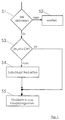
- a first Distinction function S1 first checked whether a switching command to activate the converter clutch (WK). If this is not the case, a waiting loop S2 is started. However, if in the first discriminating function S1 a command to activate the converter clutch was detected another discrimination function S3 is started, in which it is checked whether there is an actual slip dn_is less than or equal to a first limit GW1 is. Only if this condition is not met a target slip specification can be activated, otherwise it takes place the transition solely by regulating the target slip a slip map.
- the first limit value GW1 represents a sum of one predetermined target setpoint dn_soll_ziel and a threshold slip dn_schwell, the swell slip dn_schwell can be constant or from a motor torque T_Mot and an engine speed n_Mot can be dependent.
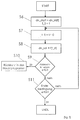
- Such a processing module S4 is shown in FIG. 3 represented schematically as a flow chart.
- the start of the processing module S4 is in a first processing function S6 the current slip value dn_start at the start of the switching command at a start time t_0 as Target slip start value read in.
- a subsequent one Processing function S7 becomes a time loop t_R for the Reduction time t_R started, which is a difference represents a current time t minus the start time t_0.
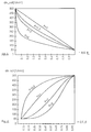
- the setpoint slip value dn_soll is reduced over time in the processing module S4 on the basis of a transition function, the course of which can be set by an applicable progression factor P.
- a target slip course according to this function is in Fig. 5 shown in principle, being for the progression factor P the values 1, 1.5, 2, 5 were used. How 5 can be seen with a progression factor, which has the value 1, the linear course of the Present the target slip reduction exactly.
- the target slip dn_soll (t_R) with this function is shown graphically bulbous , where a progression factor P with the value 1 initially results in a quasi-linear curve.
- a distinction function S9 checks whether an abort criterion has been met.
- the processing module S4 for reducing the target slip is terminated when a command is issued Deactivate the converter clutch , a push operation or a command Target slip increase is recognized. If one of these termination criteria is recognized in the differentiation function S9, a branch is made to a processing function S10 for returning to the main program.
- the processing module S4 checks whether an end condition for ending the processing module S4 is fulfilled.
- the processing module S4 is ended, if the target slip dn_soll is less than or equal to a sum from the target target slip dn_soll_ziel and the threshold desired slip is dn_soll_schwell. After that back into the subroutine for activating the converter clutch branched back.
- the distinctive function S11 of the processing module S4 for reducing the target slip found that none of the end conditions is satisfied, the system branches back to the time loop S7 and the processing module S4 is further processed.
- the discriminating function S3 of the Subroutine for activating the converter clutch recognized become that the existing actual slip dn_is smaller or is equal to the first limit value GW1, the Distinction function S3 in the processing function S5 branches to return to the main program.
- Analogous to the subroutine for Activation of the converter clutch becomes a subroutine for Deactivation of the converter clutch started.
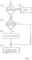
- a subroutine for deactivating the converter clutch is in FIG. 2 evident.
- a distinction function S3 ' is first started, in which it is checked whether a pressure-proportional variable is less than or equal to a respectively predetermined limit value GW2. If this is not the case, a waiting loop S2 activated.
- the pressure-proportional variable in the distinction function S3 can be an existing converter clutch pressure p_WK, an existing clutch torque T_WK or an existing engine torque T_Mot.
- the pressure-proportional variable is expediently formed as the mean value from a current and a previous value.
- the limit value GW2 depends on which pressure-proportional Size is chosen. So the limit value is GW2 a threshold pressure for the converter clutch pressure p_WK p_WK_schwell, a clutch swell torque for the clutch torque T_WK T_WK_schwell and for the engine torque T_Mot a motor threshold torque T_Mot_schwell given.
- the threshold value can be constant or be dependent on the engine speed n_Mot.
- Deactivating the converter clutch is analogous to Activation of the converter clutch via a target slip specification realized.
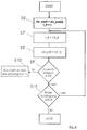
- the start value which is in a first processing function S6 'of the processing module S4' into one Start time t_0 read in at the start of the shift the current setpoint slip is dn_start.
- the target slip value dn_soll_ziel with an open or deactivated converter depends on in a map a throttle valve angle Dki and the turbine speed filed.
- the transition period or the increase time T_E is intended to serve depending on the slip speed dn_soll_diff to be bridged and the gradient of the turbine speed n_Turb_grad.
- the slip speed dn_soll_diff to be bridged represents a difference between the target-target slip dn_soll_ziel and the starting slip dn_start.
- FIG. 6 The course of the target slip during the target slip increase after this transition function is shown in FIG. 6, the different curves resulting from the use of different progression factors with the values 0.5, 1, 2, 3. As can be seen from Fig. 6, the curves run bulbous , where using a progression factor with the value 1 initially results in a quasi-linear curve.
- dn_soll (t_E) dn_start + dn_soll_grad * t_E + dn_soll_basis wherein dn_soll_grad in turn represents a target slip gradient, which is dependent on the gradient of the turbine speed n_Turb_grad.
- a distinction function S9' checks whether an abort criterion is met. The processing module S4 'for increasing the target slip is terminated when a command is issued Activate the converter clutch or an order Target slip reduction is recognized.
- the processing module S4 ' is in the one in question Execution variant ended when in the distinguishing function S11 'is recognized that the converter clutch pressure p_WK less than or equal to the threshold pressure p_WK_schwell is or the specified duration of the target slip increase T_E has expired.
- the processing function S5 'becomes a return activated in the main program when in the distinguishing function S3 'of the subroutine for deactivating the 2 is found that the selected pressure-proportional size smaller than or equal to is predetermined limit value GW2.
Landscapes
- Engineering & Computer Science (AREA)
- General Engineering & Computer Science (AREA)
- Mechanical Engineering (AREA)
- Control Of Fluid Gearings (AREA)
Applications Claiming Priority (2)
| Application Number | Priority Date | Filing Date | Title |
|---|---|---|---|
| DE19705693 | 1997-02-14 | ||
| DE19705693A DE19705693C1 (de) | 1997-02-14 | 1997-02-14 | Verfahren zur Regelung eines Schaltvorganges zwischen einem aktivierten und einem deaktivierten Zustand einer Wandlerkupplung |
Publications (2)
| Publication Number | Publication Date |
|---|---|
| EP0860632A1 true EP0860632A1 (fr) | 1998-08-26 |
| EP0860632B1 EP0860632B1 (fr) | 1999-08-04 |
Family
ID=7820264
Family Applications (1)
| Application Number | Title | Priority Date | Filing Date |
|---|---|---|---|
| EP98102179A Expired - Lifetime EP0860632B1 (fr) | 1997-02-14 | 1998-02-09 | Méthode de commande de changement entre un état embrayé et désembrayé d'un embrayage à pontage d'un convertisseur de couple |
Country Status (2)
| Country | Link |
|---|---|
| EP (1) | EP0860632B1 (fr) |
| DE (2) | DE19705693C1 (fr) |
Citations (3)
| Publication number | Priority date | Publication date | Assignee | Title |
|---|---|---|---|---|
| US4993527A (en) * | 1988-04-29 | 1991-02-19 | Chrysler Corporation | Method of determining and controlling the lock-up of a torque converter in an electronic automatic transmission system |
| EP0707165A2 (fr) * | 1994-10-14 | 1996-04-17 | Ford Motor Company Limited | Transmission automatique à plusieurs vitesses avec convertisseur de couple |
| US5531302A (en) * | 1994-09-02 | 1996-07-02 | General Motors Corporation | Controlled capacity torque converter clutch lock-up transition control |
-
1997
- 1997-02-14 DE DE19705693A patent/DE19705693C1/de not_active Expired - Fee Related
-
1998
- 1998-02-09 EP EP98102179A patent/EP0860632B1/fr not_active Expired - Lifetime
- 1998-02-09 DE DE59800020T patent/DE59800020D1/de not_active Expired - Lifetime
Patent Citations (3)
| Publication number | Priority date | Publication date | Assignee | Title |
|---|---|---|---|---|
| US4993527A (en) * | 1988-04-29 | 1991-02-19 | Chrysler Corporation | Method of determining and controlling the lock-up of a torque converter in an electronic automatic transmission system |
| US5531302A (en) * | 1994-09-02 | 1996-07-02 | General Motors Corporation | Controlled capacity torque converter clutch lock-up transition control |
| EP0707165A2 (fr) * | 1994-10-14 | 1996-04-17 | Ford Motor Company Limited | Transmission automatique à plusieurs vitesses avec convertisseur de couple |
Non-Patent Citations (2)
| Title |
|---|
| "Wandlerkupplung", ATZ AUTOMOBILTECHNISCHE ZEITSCHRIFT, vol. 96, no. 11, 1994, STUTTGART, DE, pages 690 - 697, XP000478695 * |
| ATZ AUTOMOBILTECHNISCHE ZEITSCHRIFT 96, 1994, pages 11 |
Also Published As
| Publication number | Publication date |
|---|---|
| DE19705693C1 (de) | 1998-05-14 |
| DE59800020D1 (de) | 1999-09-09 |
| EP0860632B1 (fr) | 1999-08-04 |
Similar Documents
| Publication | Publication Date | Title |
|---|---|---|
| EP0670789B1 (fr) | Procede permettant de moduler le couple de sortie d'une boite de vitesses automatique | |
| DE4028710C2 (de) | Steuervorrichtung für eine schlupfsteuerbare Überbrückungskupplung eines hydrodynamischen Drehmomentwandlers eines Kraftfahrzeug-Automatikgetriebes | |
| EP0001298A1 (fr) | Dispositif de changement de vitesse pour une transmission commandée sous charge | |
| EP0713985B1 (fr) | Dispositif et méthode de commande d'une transmission à variation continue | |
| DE69428625T2 (de) | Schaltsteuerung für ein automatisches Getriebe | |
| DE4411938A1 (de) | Steuereinrichtung und Steuerverfahren für ein stufenloses Getriebe | |
| EP0426745B1 (fr) | Procede et dispositif de commande de l'embrayage | |
| EP0651182B1 (fr) | Procédé de commande d'une variable de réglage, déterminant la différence de vitesse de rotation d'un embrayage d'automobile | |
| DE3636463A1 (de) | Verfahren und vorrichtung zur steuerung des stufenlos veraenderlichen uebersetzungsverhaeltnisses eines kegelscheibenumschlingungsgetriebes in einem kraftfahrzeug | |
| DE60109987T2 (de) | Überbrückungskupplungssteuerung | |
| DE19823033B4 (de) | Überbrückungsschlupfsteuereinrichtung für ein automatisches Getriebe | |
| EP0280757A1 (fr) | Dispositif de régulation et de commande pour une boîte de vitesses à variation continue pour véhicules à moteur | |
| WO2000006412A1 (fr) | Procede de reglage d'un rapport de transmission d'une boite automatique a rapports variables de façon continue, equipee d'un variateur | |
| EP0639476B1 (fr) | Procédé de réduire le couple d'un moteur à combustion interne lors du changement de vitesse d'une transmission | |
| DE19705956C1 (de) | Verfahren zur Regelung einer Wandlerkupplung bei einem Anfahrvorgang | |
| DE4006062A1 (de) | Schaltsteuersystem fuer ein automatisches getriebe mit verbesserter schaltuebergangscharakteristik | |
| DE102019201711A1 (de) | Verfahren zur Steuerung eines Antriebsstranges eines Fahrzeuges, insbesondere eines Kraftfahrzeuges | |
| EP0860632B1 (fr) | Méthode de commande de changement entre un état embrayé et désembrayé d'un embrayage à pontage d'un convertisseur de couple | |
| EP0859172B1 (fr) | Méthode de commande d'un embrayage de pontage de convertisseur de couple pendant un changement de vitesse de transmission | |
| DE19826736B4 (de) | Drehzahländerungs-Übergangssteuervorrichtung für ein automatisches Getriebe | |
| EP0713986B1 (fr) | Dispositif et méthode de commande d'une transmission à variation continue | |
| EP0912845A1 (fr) | Procede pour adapter l'etat d'embrayage d'un embrayage de pontage du convertisseur d'une boite automatique de vitesses | |
| DE102017211189A1 (de) | Verfahren zum Bestimmen eines Betriebszustandes reibschlüssiger Fahrtrichtungskupplungen eines Fahrzeugantriebsstranges | |
| DE10230828B4 (de) | Verfahren und Vorrichtung zur Regelung der Ausgangsgröße einer Antriebseinheit eines Fahrzeugs | |
| DE3909032C2 (de) | Vorrichtung zur automatischen Betätigung einer im Drehmomentübertragungsweg zwischen Motor und Schaltgetriebe eines Kraftfahrzeuges angeordneten Anfahr-/Schaltkupplung |
Legal Events
| Date | Code | Title | Description |
|---|---|---|---|
| PUAI | Public reference made under article 153(3) epc to a published international application that has entered the european phase |
Free format text: ORIGINAL CODE: 0009012 |
|
| AK | Designated contracting states |
Kind code of ref document: A1 Designated state(s): DE FR GB |
|
| AX | Request for extension of the european patent |
Free format text: AL;LT;LV;MK;RO;SI |
|
| GRAG | Despatch of communication of intention to grant |
Free format text: ORIGINAL CODE: EPIDOS AGRA |
|
| 17P | Request for examination filed |
Effective date: 19980909 |
|
| GRAG | Despatch of communication of intention to grant |
Free format text: ORIGINAL CODE: EPIDOS AGRA |
|
| GRAH | Despatch of communication of intention to grant a patent |
Free format text: ORIGINAL CODE: EPIDOS IGRA |
|
| 17Q | First examination report despatched |
Effective date: 19981015 |
|
| GRAH | Despatch of communication of intention to grant a patent |
Free format text: ORIGINAL CODE: EPIDOS IGRA |
|
| AKX | Designation fees paid |
Free format text: DE FR GB |
|
| RBV | Designated contracting states (corrected) |
Designated state(s): DE FR GB |
|
| GRAA | (expected) grant |
Free format text: ORIGINAL CODE: 0009210 |
|
| AK | Designated contracting states |
Kind code of ref document: B1 Designated state(s): DE FR GB |
|
| GBT | Gb: translation of ep patent filed (gb section 77(6)(a)/1977) |
Effective date: 19990806 |
|
| REF | Corresponds to: |
Ref document number: 59800020 Country of ref document: DE Date of ref document: 19990909 |
|
| ET | Fr: translation filed | ||
| PLBE | No opposition filed within time limit |
Free format text: ORIGINAL CODE: 0009261 |
|
| STAA | Information on the status of an ep patent application or granted ep patent |
Free format text: STATUS: NO OPPOSITION FILED WITHIN TIME LIMIT |
|
| 26N | No opposition filed | ||
| REG | Reference to a national code |
Ref country code: GB Ref legal event code: IF02 |
|
| PG25 | Lapsed in a contracting state [announced via postgrant information from national office to epo] |
Ref country code: GB Free format text: LAPSE BECAUSE OF NON-PAYMENT OF DUE FEES Effective date: 20020209 |
|
| GBPC | Gb: european patent ceased through non-payment of renewal fee |
Effective date: 20020209 |
|
| PGFP | Annual fee paid to national office [announced via postgrant information from national office to epo] |
Ref country code: FR Payment date: 20040210 Year of fee payment: 7 |
|
| PG25 | Lapsed in a contracting state [announced via postgrant information from national office to epo] |
Ref country code: FR Free format text: LAPSE BECAUSE OF NON-PAYMENT OF DUE FEES Effective date: 20051031 |
|
| REG | Reference to a national code |
Ref country code: FR Ref legal event code: ST Effective date: 20051031 |
|
| PGFP | Annual fee paid to national office [announced via postgrant information from national office to epo] |
Ref country code: DE Payment date: 20170131 Year of fee payment: 20 |
|
| REG | Reference to a national code |
Ref country code: DE Ref legal event code: R071 Ref document number: 59800020 Country of ref document: DE |