EP0860646A2 - Sauerstoffanreichungsapparat - Google Patents
Sauerstoffanreichungsapparat Download PDFInfo
- Publication number
- EP0860646A2 EP0860646A2 EP98300882A EP98300882A EP0860646A2 EP 0860646 A2 EP0860646 A2 EP 0860646A2 EP 98300882 A EP98300882 A EP 98300882A EP 98300882 A EP98300882 A EP 98300882A EP 0860646 A2 EP0860646 A2 EP 0860646A2
- Authority
- EP
- European Patent Office
- Prior art keywords
- pressure
- oxygen
- air
- enriched air
- outlet
- Prior art date
- Legal status (The legal status is an assumption and is not a legal conclusion. Google has not performed a legal analysis and makes no representation as to the accuracy of the status listed.)
- Granted
Links
Images





Classifications
-
- B—PERFORMING OPERATIONS; TRANSPORTING
- B01—PHYSICAL OR CHEMICAL PROCESSES OR APPARATUS IN GENERAL
- B01D—SEPARATION
- B01D53/00—Separation of gases or vapours; Recovering vapours of volatile solvents from gases; Chemical or biological purification of waste gases, e.g. engine exhaust gases, smoke, fumes, flue gases, aerosols
- B01D53/02—Separation of gases or vapours; Recovering vapours of volatile solvents from gases; Chemical or biological purification of waste gases, e.g. engine exhaust gases, smoke, fumes, flue gases, aerosols by adsorption, e.g. preparative gas chromatography
- B01D53/04—Separation of gases or vapours; Recovering vapours of volatile solvents from gases; Chemical or biological purification of waste gases, e.g. engine exhaust gases, smoke, fumes, flue gases, aerosols by adsorption, e.g. preparative gas chromatography with stationary adsorbents
- B01D53/0407—Constructional details of adsorbing systems
- B01D53/0446—Means for feeding or distributing gases
-
- F—MECHANICAL ENGINEERING; LIGHTING; HEATING; WEAPONS; BLASTING
- F17—STORING OR DISTRIBUTING GASES OR LIQUIDS
- F17C—VESSELS FOR CONTAINING OR STORING COMPRESSED, LIQUEFIED OR SOLIDIFIED GASES; FIXED-CAPACITY GAS-HOLDERS; FILLING VESSELS WITH, OR DISCHARGING FROM VESSELS, COMPRESSED, LIQUEFIED, OR SOLIDIFIED GASES
- F17C7/00—Methods or apparatus for discharging liquefied, solidified, or compressed gases from pressure vessels, not covered by another subclass
-
- B—PERFORMING OPERATIONS; TRANSPORTING
- B01—PHYSICAL OR CHEMICAL PROCESSES OR APPARATUS IN GENERAL
- B01D—SEPARATION
- B01D2253/00—Adsorbents used in seperation treatment of gases and vapours
- B01D2253/10—Inorganic adsorbents
- B01D2253/106—Silica or silicates
- B01D2253/108—Zeolites
-
- B—PERFORMING OPERATIONS; TRANSPORTING
- B01—PHYSICAL OR CHEMICAL PROCESSES OR APPARATUS IN GENERAL
- B01D—SEPARATION
- B01D2256/00—Main component in the product gas stream after treatment
- B01D2256/12—Oxygen
-
- B—PERFORMING OPERATIONS; TRANSPORTING
- B01—PHYSICAL OR CHEMICAL PROCESSES OR APPARATUS IN GENERAL
- B01D—SEPARATION
- B01D2257/00—Components to be removed
- B01D2257/10—Single element gases other than halogens
- B01D2257/102—Nitrogen
-
- B—PERFORMING OPERATIONS; TRANSPORTING
- B01—PHYSICAL OR CHEMICAL PROCESSES OR APPARATUS IN GENERAL
- B01D—SEPARATION
- B01D2259/00—Type of treatment
- B01D2259/40—Further details for adsorption processes and devices
- B01D2259/402—Further details for adsorption processes and devices using two beds
-
- B—PERFORMING OPERATIONS; TRANSPORTING
- B01—PHYSICAL OR CHEMICAL PROCESSES OR APPARATUS IN GENERAL
- B01D—SEPARATION
- B01D2259/00—Type of treatment
- B01D2259/45—Gas separation or purification devices adapted for specific applications
- B01D2259/4533—Gas separation or purification devices adapted for specific applications for medical purposes
-
- B—PERFORMING OPERATIONS; TRANSPORTING
- B01—PHYSICAL OR CHEMICAL PROCESSES OR APPARATUS IN GENERAL
- B01D—SEPARATION
- B01D53/00—Separation of gases or vapours; Recovering vapours of volatile solvents from gases; Chemical or biological purification of waste gases, e.g. engine exhaust gases, smoke, fumes, flue gases, aerosols
- B01D53/02—Separation of gases or vapours; Recovering vapours of volatile solvents from gases; Chemical or biological purification of waste gases, e.g. engine exhaust gases, smoke, fumes, flue gases, aerosols by adsorption, e.g. preparative gas chromatography
- B01D53/04—Separation of gases or vapours; Recovering vapours of volatile solvents from gases; Chemical or biological purification of waste gases, e.g. engine exhaust gases, smoke, fumes, flue gases, aerosols by adsorption, e.g. preparative gas chromatography with stationary adsorbents
- B01D53/047—Pressure swing adsorption
-
- F—MECHANICAL ENGINEERING; LIGHTING; HEATING; WEAPONS; BLASTING
- F17—STORING OR DISTRIBUTING GASES OR LIQUIDS
- F17C—VESSELS FOR CONTAINING OR STORING COMPRESSED, LIQUEFIED OR SOLIDIFIED GASES; FIXED-CAPACITY GAS-HOLDERS; FILLING VESSELS WITH, OR DISCHARGING FROM VESSELS, COMPRESSED, LIQUEFIED, OR SOLIDIFIED GASES
- F17C2205/00—Vessel construction, in particular mounting arrangements, attachments or identifications means
- F17C2205/03—Fluid connections, filters, valves, closure means or other attachments
- F17C2205/0302—Fittings, valves, filters, or components in connection with the gas storage device
- F17C2205/0311—Closure means
- F17C2205/0314—Closure means breakable, e.g. with burst discs
-
- F—MECHANICAL ENGINEERING; LIGHTING; HEATING; WEAPONS; BLASTING
- F17—STORING OR DISTRIBUTING GASES OR LIQUIDS
- F17C—VESSELS FOR CONTAINING OR STORING COMPRESSED, LIQUEFIED OR SOLIDIFIED GASES; FIXED-CAPACITY GAS-HOLDERS; FILLING VESSELS WITH, OR DISCHARGING FROM VESSELS, COMPRESSED, LIQUEFIED, OR SOLIDIFIED GASES
- F17C2205/00—Vessel construction, in particular mounting arrangements, attachments or identifications means
- F17C2205/03—Fluid connections, filters, valves, closure means or other attachments
- F17C2205/0302—Fittings, valves, filters, or components in connection with the gas storage device
- F17C2205/0323—Valves
- F17C2205/0326—Valves electrically actuated
-
- F—MECHANICAL ENGINEERING; LIGHTING; HEATING; WEAPONS; BLASTING
- F17—STORING OR DISTRIBUTING GASES OR LIQUIDS
- F17C—VESSELS FOR CONTAINING OR STORING COMPRESSED, LIQUEFIED OR SOLIDIFIED GASES; FIXED-CAPACITY GAS-HOLDERS; FILLING VESSELS WITH, OR DISCHARGING FROM VESSELS, COMPRESSED, LIQUEFIED, OR SOLIDIFIED GASES
- F17C2205/00—Vessel construction, in particular mounting arrangements, attachments or identifications means
- F17C2205/03—Fluid connections, filters, valves, closure means or other attachments
- F17C2205/0302—Fittings, valves, filters, or components in connection with the gas storage device
- F17C2205/0323—Valves
- F17C2205/0329—Valves manually actuated
-
- F—MECHANICAL ENGINEERING; LIGHTING; HEATING; WEAPONS; BLASTING
- F17—STORING OR DISTRIBUTING GASES OR LIQUIDS
- F17C—VESSELS FOR CONTAINING OR STORING COMPRESSED, LIQUEFIED OR SOLIDIFIED GASES; FIXED-CAPACITY GAS-HOLDERS; FILLING VESSELS WITH, OR DISCHARGING FROM VESSELS, COMPRESSED, LIQUEFIED, OR SOLIDIFIED GASES
- F17C2205/00—Vessel construction, in particular mounting arrangements, attachments or identifications means
- F17C2205/03—Fluid connections, filters, valves, closure means or other attachments
- F17C2205/0302—Fittings, valves, filters, or components in connection with the gas storage device
- F17C2205/0323—Valves
- F17C2205/0332—Safety valves or pressure relief valves
-
- F—MECHANICAL ENGINEERING; LIGHTING; HEATING; WEAPONS; BLASTING
- F17—STORING OR DISTRIBUTING GASES OR LIQUIDS
- F17C—VESSELS FOR CONTAINING OR STORING COMPRESSED, LIQUEFIED OR SOLIDIFIED GASES; FIXED-CAPACITY GAS-HOLDERS; FILLING VESSELS WITH, OR DISCHARGING FROM VESSELS, COMPRESSED, LIQUEFIED, OR SOLIDIFIED GASES
- F17C2205/00—Vessel construction, in particular mounting arrangements, attachments or identifications means
- F17C2205/03—Fluid connections, filters, valves, closure means or other attachments
- F17C2205/0302—Fittings, valves, filters, or components in connection with the gas storage device
- F17C2205/0323—Valves
- F17C2205/0335—Check-valves or non-return valves
-
- F—MECHANICAL ENGINEERING; LIGHTING; HEATING; WEAPONS; BLASTING
- F17—STORING OR DISTRIBUTING GASES OR LIQUIDS
- F17C—VESSELS FOR CONTAINING OR STORING COMPRESSED, LIQUEFIED OR SOLIDIFIED GASES; FIXED-CAPACITY GAS-HOLDERS; FILLING VESSELS WITH, OR DISCHARGING FROM VESSELS, COMPRESSED, LIQUEFIED, OR SOLIDIFIED GASES
- F17C2205/00—Vessel construction, in particular mounting arrangements, attachments or identifications means
- F17C2205/03—Fluid connections, filters, valves, closure means or other attachments
- F17C2205/0302—Fittings, valves, filters, or components in connection with the gas storage device
- F17C2205/0338—Pressure regulators
-
- F—MECHANICAL ENGINEERING; LIGHTING; HEATING; WEAPONS; BLASTING
- F17—STORING OR DISTRIBUTING GASES OR LIQUIDS
- F17C—VESSELS FOR CONTAINING OR STORING COMPRESSED, LIQUEFIED OR SOLIDIFIED GASES; FIXED-CAPACITY GAS-HOLDERS; FILLING VESSELS WITH, OR DISCHARGING FROM VESSELS, COMPRESSED, LIQUEFIED, OR SOLIDIFIED GASES
- F17C2205/00—Vessel construction, in particular mounting arrangements, attachments or identifications means
- F17C2205/03—Fluid connections, filters, valves, closure means or other attachments
- F17C2205/0302—Fittings, valves, filters, or components in connection with the gas storage device
- F17C2205/0341—Filters
-
- F—MECHANICAL ENGINEERING; LIGHTING; HEATING; WEAPONS; BLASTING
- F17—STORING OR DISTRIBUTING GASES OR LIQUIDS
- F17C—VESSELS FOR CONTAINING OR STORING COMPRESSED, LIQUEFIED OR SOLIDIFIED GASES; FIXED-CAPACITY GAS-HOLDERS; FILLING VESSELS WITH, OR DISCHARGING FROM VESSELS, COMPRESSED, LIQUEFIED, OR SOLIDIFIED GASES
- F17C2205/00—Vessel construction, in particular mounting arrangements, attachments or identifications means
- F17C2205/03—Fluid connections, filters, valves, closure means or other attachments
- F17C2205/0302—Fittings, valves, filters, or components in connection with the gas storage device
- F17C2205/037—Quick connecting means, e.g. couplings
-
- F—MECHANICAL ENGINEERING; LIGHTING; HEATING; WEAPONS; BLASTING
- F17—STORING OR DISTRIBUTING GASES OR LIQUIDS
- F17C—VESSELS FOR CONTAINING OR STORING COMPRESSED, LIQUEFIED OR SOLIDIFIED GASES; FIXED-CAPACITY GAS-HOLDERS; FILLING VESSELS WITH, OR DISCHARGING FROM VESSELS, COMPRESSED, LIQUEFIED, OR SOLIDIFIED GASES
- F17C2221/00—Handled fluid, in particular type of fluid
- F17C2221/01—Pure fluids
- F17C2221/011—Oxygen
-
- F—MECHANICAL ENGINEERING; LIGHTING; HEATING; WEAPONS; BLASTING
- F17—STORING OR DISTRIBUTING GASES OR LIQUIDS
- F17C—VESSELS FOR CONTAINING OR STORING COMPRESSED, LIQUEFIED OR SOLIDIFIED GASES; FIXED-CAPACITY GAS-HOLDERS; FILLING VESSELS WITH, OR DISCHARGING FROM VESSELS, COMPRESSED, LIQUEFIED, OR SOLIDIFIED GASES
- F17C2221/00—Handled fluid, in particular type of fluid
- F17C2221/03—Mixtures
- F17C2221/031—Air
-
- F—MECHANICAL ENGINEERING; LIGHTING; HEATING; WEAPONS; BLASTING
- F17—STORING OR DISTRIBUTING GASES OR LIQUIDS
- F17C—VESSELS FOR CONTAINING OR STORING COMPRESSED, LIQUEFIED OR SOLIDIFIED GASES; FIXED-CAPACITY GAS-HOLDERS; FILLING VESSELS WITH, OR DISCHARGING FROM VESSELS, COMPRESSED, LIQUEFIED, OR SOLIDIFIED GASES
- F17C2223/00—Handled fluid before transfer, i.e. state of fluid when stored in the vessel or before transfer from the vessel
- F17C2223/01—Handled fluid before transfer, i.e. state of fluid when stored in the vessel or before transfer from the vessel characterised by the phase
- F17C2223/0107—Single phase
- F17C2223/0123—Single phase gaseous, e.g. CNG, GNC
-
- F—MECHANICAL ENGINEERING; LIGHTING; HEATING; WEAPONS; BLASTING
- F17—STORING OR DISTRIBUTING GASES OR LIQUIDS
- F17C—VESSELS FOR CONTAINING OR STORING COMPRESSED, LIQUEFIED OR SOLIDIFIED GASES; FIXED-CAPACITY GAS-HOLDERS; FILLING VESSELS WITH, OR DISCHARGING FROM VESSELS, COMPRESSED, LIQUEFIED, OR SOLIDIFIED GASES
- F17C2225/00—Handled fluid after transfer, i.e. state of fluid after transfer from the vessel
- F17C2225/03—Handled fluid after transfer, i.e. state of fluid after transfer from the vessel characterised by the pressure level
- F17C2225/033—Small pressure, e.g. for liquefied gas
-
- F—MECHANICAL ENGINEERING; LIGHTING; HEATING; WEAPONS; BLASTING
- F17—STORING OR DISTRIBUTING GASES OR LIQUIDS
- F17C—VESSELS FOR CONTAINING OR STORING COMPRESSED, LIQUEFIED OR SOLIDIFIED GASES; FIXED-CAPACITY GAS-HOLDERS; FILLING VESSELS WITH, OR DISCHARGING FROM VESSELS, COMPRESSED, LIQUEFIED, OR SOLIDIFIED GASES
- F17C2225/00—Handled fluid after transfer, i.e. state of fluid after transfer from the vessel
- F17C2225/03—Handled fluid after transfer, i.e. state of fluid after transfer from the vessel characterised by the pressure level
- F17C2225/036—Very high pressure, i.e. above 80 bars
-
- F—MECHANICAL ENGINEERING; LIGHTING; HEATING; WEAPONS; BLASTING
- F17—STORING OR DISTRIBUTING GASES OR LIQUIDS
- F17C—VESSELS FOR CONTAINING OR STORING COMPRESSED, LIQUEFIED OR SOLIDIFIED GASES; FIXED-CAPACITY GAS-HOLDERS; FILLING VESSELS WITH, OR DISCHARGING FROM VESSELS, COMPRESSED, LIQUEFIED, OR SOLIDIFIED GASES
- F17C2227/00—Transfer of fluids, i.e. method or means for transferring the fluid; Heat exchange with the fluid
- F17C2227/01—Propulsion of the fluid
- F17C2227/0128—Propulsion of the fluid with pumps or compressors
- F17C2227/0157—Compressors
-
- F—MECHANICAL ENGINEERING; LIGHTING; HEATING; WEAPONS; BLASTING
- F17—STORING OR DISTRIBUTING GASES OR LIQUIDS
- F17C—VESSELS FOR CONTAINING OR STORING COMPRESSED, LIQUEFIED OR SOLIDIFIED GASES; FIXED-CAPACITY GAS-HOLDERS; FILLING VESSELS WITH, OR DISCHARGING FROM VESSELS, COMPRESSED, LIQUEFIED, OR SOLIDIFIED GASES
- F17C2250/00—Accessories; Control means; Indicating, measuring or monitoring of parameters
- F17C2250/04—Indicating or measuring of parameters as input values
- F17C2250/0404—Parameters indicated or measured
- F17C2250/0443—Flow or movement of content
-
- F—MECHANICAL ENGINEERING; LIGHTING; HEATING; WEAPONS; BLASTING
- F17—STORING OR DISTRIBUTING GASES OR LIQUIDS
- F17C—VESSELS FOR CONTAINING OR STORING COMPRESSED, LIQUEFIED OR SOLIDIFIED GASES; FIXED-CAPACITY GAS-HOLDERS; FILLING VESSELS WITH, OR DISCHARGING FROM VESSELS, COMPRESSED, LIQUEFIED, OR SOLIDIFIED GASES
- F17C2250/00—Accessories; Control means; Indicating, measuring or monitoring of parameters
- F17C2250/04—Indicating or measuring of parameters as input values
- F17C2250/0404—Parameters indicated or measured
- F17C2250/0447—Composition; Humidity
-
- F—MECHANICAL ENGINEERING; LIGHTING; HEATING; WEAPONS; BLASTING
- F17—STORING OR DISTRIBUTING GASES OR LIQUIDS
- F17C—VESSELS FOR CONTAINING OR STORING COMPRESSED, LIQUEFIED OR SOLIDIFIED GASES; FIXED-CAPACITY GAS-HOLDERS; FILLING VESSELS WITH, OR DISCHARGING FROM VESSELS, COMPRESSED, LIQUEFIED, OR SOLIDIFIED GASES
- F17C2250/00—Accessories; Control means; Indicating, measuring or monitoring of parameters
- F17C2250/06—Controlling or regulating of parameters as output values
- F17C2250/0605—Parameters
- F17C2250/0626—Pressure
-
- F—MECHANICAL ENGINEERING; LIGHTING; HEATING; WEAPONS; BLASTING
- F17—STORING OR DISTRIBUTING GASES OR LIQUIDS
- F17C—VESSELS FOR CONTAINING OR STORING COMPRESSED, LIQUEFIED OR SOLIDIFIED GASES; FIXED-CAPACITY GAS-HOLDERS; FILLING VESSELS WITH, OR DISCHARGING FROM VESSELS, COMPRESSED, LIQUEFIED, OR SOLIDIFIED GASES
- F17C2250/00—Accessories; Control means; Indicating, measuring or monitoring of parameters
- F17C2250/06—Controlling or regulating of parameters as output values
- F17C2250/0605—Parameters
- F17C2250/0636—Flow or movement of content
-
- F—MECHANICAL ENGINEERING; LIGHTING; HEATING; WEAPONS; BLASTING
- F17—STORING OR DISTRIBUTING GASES OR LIQUIDS
- F17C—VESSELS FOR CONTAINING OR STORING COMPRESSED, LIQUEFIED OR SOLIDIFIED GASES; FIXED-CAPACITY GAS-HOLDERS; FILLING VESSELS WITH, OR DISCHARGING FROM VESSELS, COMPRESSED, LIQUEFIED, OR SOLIDIFIED GASES
- F17C2265/00—Effects achieved by gas storage or gas handling
- F17C2265/01—Purifying the fluid
- F17C2265/012—Purifying the fluid by filtering
-
- F—MECHANICAL ENGINEERING; LIGHTING; HEATING; WEAPONS; BLASTING
- F17—STORING OR DISTRIBUTING GASES OR LIQUIDS
- F17C—VESSELS FOR CONTAINING OR STORING COMPRESSED, LIQUEFIED OR SOLIDIFIED GASES; FIXED-CAPACITY GAS-HOLDERS; FILLING VESSELS WITH, OR DISCHARGING FROM VESSELS, COMPRESSED, LIQUEFIED, OR SOLIDIFIED GASES
- F17C2270/00—Applications
- F17C2270/02—Applications for medical applications
- F17C2270/025—Breathing
Definitions
- the present invention provides an oxygen concentrator and cylinder recharger and in particular provides a home health care oxygen concentrator and a cylinder recharger that is capable of simultaneously or independently providing oxygen-enriched air at a low pressure and at a high pressure.
- a home health care oxygen concentrator and a cylinder recharger that is capable of simultaneously or independently providing oxygen-enriched air at a low pressure and at a high pressure.
- Such provision of oxygen-enriched air at two different pressures enables the apparatus to be utilized for the provision of oxygen-enriched air at a pressure suitable for use by a patient while at the same time providing oxygen-enriched air at a pressure suitable for recharging of a cylinder, thereby providing the patient with the option to be mobile.
- oxygen-enriched air sometimes referred to as oxygen
- One particular situation where such low pressure oxygen-enriched air is required is in the health care field, both in the health care field within various institutions as well as within a patient's home. In such situations, it may be necessary to provide a continuous flow of low pressure oxygen-enriched air to a patient on an on-going basis. While such patients may be able to withstand the absence of the flow of oxygen-enriched air for short periods of time, such patients frequently are unable to withstand the absence of such a flow of oxygen-enriched air for longer periods of time without suffering major health problems. In particular, such patients are normally not able to move from one location to another without oxygen-enriched air.
- Systems for the provision of a flow of low pressure oxygen-enriched air include distillation processes, adsorption separation processes and membrane separation processes.
- One such process is a so-called pressure swing adsorption (PSA) process which has the advantage of being able to provide oxygen-enriched air in a short period of time after the supply of a suitable feed gas e.g. compressed air, to the apparatus.
- PSA pressure swing adsorption
- An example of a pressure swing adsorption process is described in U.S. Patent 4,948,391 of Y. Noguchi, which issued August 14, 1990.
- a typical pressure swing adsorption process applied to the provision of oxygen-enriched air could comprise the following steps:
- Steps (a)-(e) effect the separation of nitrogen from the air so as to provide oxygen-enriched air
- steps (f) and (g) effect regeneration of the column used in the process. This permits continuous and long-term use of the pressure swing adsorption process to provide oxygen-enriched air.
- One of the disadvantages of known processes for the supply of oxygen-enriched air at low pressure is that such processes lack the flexibility to allow the patient to be located at a fixed location but also to be able to move from that location with relative ease with an assurance that the source of oxygen-enriched air is sufficient. For instance, the patient may wish or need to be able to move from a bed or other similar location, e.g. to use toilet facilities, prepare meals, go to another room or change locations for other reasons.
- Such mobility with existing processes generally requires a patient to be disconnected from a first source of low pressure oxygen-enriched air and to be re-connected to a second system for provision of such air and which is mobile e.g. a cylinder of oxygen-enriched air.
- the patient would want an assurance that the source of oxygen-enriched air is sufficient, which would be of particular concern if the patient wished to be mobile for an extended period of time e.g. a day or weekend, without having to re-fill the mobile, or ambulatory, cylinder at a dealer or distributor.
- Apparatus has now been found that is capable of simultaneously providing low pressure oxygen-enriched air for use by a patient as well as high pressure oxygen-enriched air for the filling of a pressure cylinder.
- one aspect of the present invention provides an apparatus for providing oxygen-enriched air comprising, in combination:
- the present invention provides a method for providing oxygen-enriched air at a first pressure and at a second pressure, said second pressure being greater than the first pressure, said method comprising:
- the present invention provides apparatus for providing oxygen-enriched air comprising, in combination:
- the air separation system is a pressure swing absorption system
- the oxygen-enriched air from the pressure swing adsorption system is provided either simultaneously or independently to said pressure intensifier.
- the apparatus further comprises an air compressor for providing air to said pressure swing adsorption system, said air compressor having an inlet and exhaust air sound suppression system.
- the low pressure oxygen-enriched air separation system may be an oxygen generator, a distiller, an air separator or a membrane separator, but it will be described herein with reference to the preferred embodiment in which it is a pressure swing absorption system.
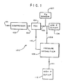
- Fig. 1 shows apparatus of the invention, generally indicated by 100, in block format.
- Ambient air 101 is connected to compressor 102.
- Outlet 103 from compressor 102 is connected to pressure swing adsorber (PSA) 104 and pressure intensifier 109 (see Fig. 2).
- Outlet 105 from pressure swing adsorber 104 is connected to oxygen sensor 107, low pressure outlet 106, and through tubing 108, to pressure intensifier 109.
- Pressure intensifier 109 is connected by tubing 111 to high pressure outlet 112, as well as being interconnected by tubing 110 to pressure swing adsorber 104.
- ambient air enters air inlet 101 and is pressurized in compressor 102.
- the pressurized air is fed to pressure swing adsorber 104, as well as being fed to pressure intensifier 109 when the latter is energized (see Fig. 2).
- the oxygen-enriched air from pressure swing adsorber 104 is monitored by oxygen sensor 107, as well as fed to low pressure outlet 106 for use by a patient.
- oxygen-enriched air is fed to pressure intensifier 109.
- Pressurized oxygen-enriched air is fed from pressure intensifier 109 to high pressure outlet 112 where it may be used to re-charge a cylinder of oxygen-enriched air.
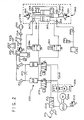
- Fig. 2 shows an embodiment of an apparatus of the invention, generally indicated by 200, in greater detail.
- Apparatus 200 has inlet 101 connected in turn to particulate filter 201, tuned resonator 202 and to the inlet to compressor 203.
- Compressor 203 is driven by motor 204, and has relief valve 205.
- the outlet from compressor 203 is connected to a heat exchanger, generally indicated by 206, which has heat exchanger section 207 and cooling fan 208.
- Outlet tubing 209 from heat exchanger 207 is connected to two solenoid valves, 210 and 211, which are in a parallel relationship.
- Solenoid valves 210 and 211 are connected to a tuned resonator 212. Each of solenoid valves 210 and 211 is connected to a sieve bed, 213 and 214 respectively, which are also in a parallel relationship. Sieve beds 213 and 214 are molecular sieve beds. Each of the outlets of sieve bed 213 and 214 is connected to a check valve, 215 and 216 respectively. In addition, sieve bed 213 and 214 are interconnected through orifice 217, the interconnection being located between the outlet of each of sieve bed 213 and 214 and each of check valves 215 and 216.
- Oxygen plenum 220 is connected through orifice 221 to oxygen sensor 222 and filter 223, which is vented to the atmosphere. Oxygen plenum 220 is also connected to low pressure switch 237. The outlet of oxygen plenum 220 is connected in turn to pressure regulator 231, through orifice 232, filter 233, check valve 234, flow meter 235 to patient outlet 236.
- Patient outlet 236 is a low pressure outlet i.e. the pressure would normally be only a few inches of water, as will be understood by persons skilled in the art.
- the outlet of the oxygen plenum 220 is also connected to a pressure intensifier generally indicated by 240.
- Pressure intensifier 240 has a first stage cylinder 241 and a second stage cylinder 242, with drive air cylinder 243 located therebetween.
- the opposed sides of drive cylinder 243 are connected through solenoid valves 244 and 245 to tubing between solenoid valve 210 and sieve bed 213, and tubing between solenoid valve 211 and sieve bed 214, respectively, of the pressure swing adsorber.
- Check valve 247 is located between oxygen plenum 220 and first stage cylinder 241.
- First stage cylinder 241 is also connected through check valve 248 and check valve 250 to second stage cylinder 242.
- Rupture disc 246 is attached to first stage cylinder 241 and rupture disc 251 is attached to second stage cylinder 242.
- Filters 252 and 253 are connected to first stage cylinder 241 and second stage cylinder 242, respectively, and vented to the atmosphere.
- Check valve 249 is connected to filter 260, pressure switch 261 and pressure connection 262, which is the high pressure connection.
- Tuned resonator 202 is for sound suppression of compressor 203.
- the air is compressed to the operating pressure e.g. a pressure ranging from 20 to 30 psig.
- the compressed air obtained is routed through a fan cooled tube and fin heat exchanger 206 which cools the air before it enters the molecular sieve beds 213 and 214.
- the cooling of the air from the compressor optimizes performance of the molecular sieve beds as well as cooling the oxygen-enriched air obtained from the beds before it reaches the patient.
- Air flow into and out of the beds is controlled by two solenoid valves (valve 210 and valve 211) which allow compressed air to either enter the bed or to be vented from the bed to atmosphere.
- a normal three phase cycle is (i) a first filling phase to fill bed 213 and exhaust bed 214, (ii) an intermediate overlap phase and (iii) a second filling phase to fill bed 214 and exhaust bed 213.
- solenoid valve 210 allows compressed gas to enter bed 213 while valve 211 is venting gas from bed 214 to atmosphere.
- the molecular sieve in bed 213 adsorbs water vapour and nitrogen from the compressed air, allowing oxygen and argon to pass through the sieve.
- a portion of the gas is used as product gas which is delivered to the patient as low pressure oxygen-enriched air.
- the remainder of the oxygen-enriched air passes through an orifice, 217, and purges nitrogen and water vapour out of bed 214 as it is vented to atmosphere through solenoid valve 211.
- the pressure in bed 213 is typically approximately 30 psig and in bed 214 it is typically slightly above zero psig. At this time, bed 213 is almost saturated with nitrogen and continued flow through this bed without purging would result in nitrogen breakthrough and loss of purity in the product gas.
- overlap phase (ii) there is an overlap of approximately 1.6 seconds in which both solenoid valves 210 and 211 are switched to allow flow into both molecular sieve beds.
- This allows the air from sieve bed 213, initially at approximately 30 psig, as discussed above, to back flow through solenoid valve 210 into bed 214 which is initially at a low pressure.
- the crossflow of air in addition to the air from compressor provides a quick charge of bed 214, thereby reducing the compressor flow requirements and improving the efficiency of the system.
- the pressure in both beds is typically approximately 20 psig.
- solenoid valve 210 is switched to the vent position allowing bed 213 to vent to atmosphere until the pressure is only slightly above zero. Venting the bed to atmosphere plus back filling with product gas from bed 214 purges nitrogen and water vapour from bed 213 in preparation for the next cycle. At the same time bed 214 is providing product gas to the patient and purging bed 213. At the end of this phase, the entire cycle is repeated.
- the oxygen-enriched air from the sieve beds passes through check valves 215 and 216 into the product storage (oxygen plenum 220). From oxygen plenum 220, the oxygen-enriched air passes into pressure regulator 231, through flow control orifice 232, HEPA filter 233 and check valve 234 to flow meter 235. Regulator 231 reduces the pressure from, for example, 30 psig in the oxygen storage plenum 220 to a constant pressure e.g. 6 psig, at the inlet of flow meter 235.
- Flow meter 235 is adjustable by the patient to provide the prescribed flow rate of oxygen at very low pressure.
- a predetermined value e.g. 90%
- Pressure intensifier 240 may be standard two-stage device with a drive air cylinder and first and second stage product gas cylinders. The intensifier is turned on by opening solenoid valve 244 and 245 and which are either both open or both closed.
- a typical pressure intensifier cycle is as follows:
- the gas After leaving the pressure intensifier, the gas passes through a filter 260 and the high pressure coupling 262 before entering a pressure vessel (not shown).
- the pressure intensifier will continue to operate until the pressure is high enough to activate a pressure switch 261 in the product line which signals the controller to close solenoid valves 244 and 245.
- the first pressure is in the range of 5-10 psi and the second pressure is in the range of up to 3000 psi.
- the apparatus of the present invention is particularly adapted to be capable of providing both first and second pressures simultaneously.
- the oxygen content of the oxygen-enriched air may be varied over a wide range but is preferably at least 85% by volume. In preferred embodiments, the oxygen content is at least 90% by volume, especially in the range of 92-94% by volume.
- the oxygen concentrator described herein utilizes a pressure intensifier to raise the pressure of a portion of the oxygen-enriched air to a suitable pressure e.g. 2000 psig, for storage in pressure vessels e.g. a cylinder, for use by ambulatory patients.
- a suitable pressure e.g. 2000 psig
- the pressure intensifier will provide oxygen-enriched air at a relatively low pressure, for instance, about the pressure in the storage plenum e.g. 30 psig, but that this pressure will rise as the cylinder fills e.g. to the aforementioned 2000 psig.
- the oxygen concentrator may be operated so as to produce oxygen-enriched air having a content of, for example, 93% oxygen, and thereby meet certain regulations relating to the provision of oxygen-enriched air for patients, such oxygen-enriched air may not meet the specifications for a medical-grade oxygen.
- cylinders with adaptors meeting regulations for medical-grade oxygen may not be able to be used with the oxygen concentrator.
- a unique integrated high pressure fitting and flow controller is preferred, that allows the patient to easily and safely fill their cylinders with oxygen-enriched air e.g. 93% oxygen, from the concentrator.
- Such a high pressure fitting and flow controller is shown in Figures 3-11.
- FIG 3 shows a perspective view of a fill port adaptor body, generally indicated by 300.
- Fill port adaptor body 300 has a housing 301 with integral cradle 302, handle 303, locking clip 304 and adaptor housing 305.
- Cradle 302 of housing 301 is adapted to accept the flow controller body described herein below.
- Cradle 302 has fill port adaptor 306 therein, which is further shown in Figure 5.
- Fill port adaptor 306 is connected to handle 303, and is movable into cradle 302 using handle 303.
- Adaptor 307 extends from housing 301 from the opposed side thereof to fill port adaptor 306, and is interconnected therewith as shown in Figure 5.
- Locking clip 304 is intended to retain the flow controller body within cradle 302, as described below. Latching of the flow controller body into cradle 302 occurs automatically when the flow controller body of a cylinder is placed in the cradle. However, an operator must manually move locking clip 304 into a release position to remove the cylinder. Similarly, handle 303 must be moved before the flow controller body of a cylinder may be placed in cradle 302 or removed therefrom, to reduce risk of damage to fill port adaptor 306.
- Adaptor housing 305 is open on its upper face, as illustrated, and has housing window 308 on the opposed side thereof.
- the end of adaptor housing 305 opposed to cradle 302 has housing slot 309 therein.
- Figure 4 is a plan view of fill port adaptor port 300.
- Handle 303 is located on housing 301, and is adjacent to cradle 302.
- Locking clip 304 is shown as extending into cradle 302.
- Cradle 302 has adaptor housing 305 extending therefrom and in an aligned relationship.
- Adaptor housing 305 has housing window 308 therein, with housing slot 309 in the end thereof.
- Figure 4 shows that adaptor 307 is connected to gear rack 401 which extends into housing 301.
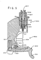
- Figure 5 shows a cross section of fill port adaptor body 300 through line A-A.
- Locking clip 304 is pivoted about locking clip pivot 501.
- Locking clip spring 504 located within housing 301 biases locking clip base 503 in an outwards direction so that locking clip lip 502 is biased into to cradle 302 to lock the flow controller body therein.
- a fill port adaptor is on the opposed side of cradle 302 to locking clip 304.
- Adaptor 307 is connected to adaptor channel 506 which is located within adaptor channel housing 507 which in turn is located within adaptor housing 512.
- Gear rack 401, shown in Fig. 4 and Fig. 6 is machined into adaptor housing 512.
- adaptor housing 512 is movable with respect to housing 301.
- Adaptor channel 506 connects with spring chamber 513 in which is located adaptor spring 508 and check valve base 509.
- Check valve base 509 extends through check valve seat 510 and terminates in adaptor pin 511. In the retracted position as shown in Fig. 5, adaptor pin 511 is within housing 301, but in the engaged position the adaptor pin extends into cradle 302.
- Figure 6 shows a cross section of the adaptor body shown in Figure 4, through D-D.
- Handle 303 is located on housing 301.
- Shaft 605 extends downward from handle 303 and connects handle 303 to pinion 601; pinion 601 is more clearly seen in Figure 7, and is attached to shaft 605 by screw 604.
- Rotation of handle 303 causes rotation of pinion 601.
- Handle 303 has, on its lower side, handle projection 608, which is shown as being located in indent 609 in housing 301. Indent 609, and a similar indent that is not shown, serve to position and retain handle 303 in predetermined locations.
- indent 609 has an adjustable screw therein (not shown), such screw being tapered or having a shoulder thereon.
- Projection 608 contacts the adjustable screw, on said taper or shoulder. Adjustment of the position of the screw adjusts the location of the taper or shoulder, and hence radially adjusts the position at which handle 303 is positioned and retained. This permits precise adjustment of the positioning of the fill port adaptor.
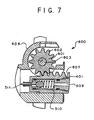
- FIG 7 shows the rack and pinion, generally indicated by 600.
- Rack and pinion 600 has pinion 601 with pinion cogs 602.
- Pinion 601 rotates about pinion shaft 603, which extends down from handle 303, forming part thereof, as discussed above.
- Pinion 601 is located within pinion housing 606 which is part of housing 301.
- Pinion cogs 602 intermesh with ratchet slots 607 of ratchet 401.
- Ratchet 401 forms part of adaptor channel housing 507 illustrated in Figure 5.
- FIG 8 illustrates the flow controller body, generally indicated by 700.
- Flow controller body 700 has pressure gauge 701, rupture disc housing 709, outlet fitting 706, and flow restrictor 704.
- Outlet fitting 706 is adapted to receive a flexible hose.
- the body is adapted to be threaded onto a high pressure cylinder by threaded port 705, flow restrictor 704 being located within threaded port 705.
- Flow controller body 700 has an integral cradle housing 702 which is shaped and dimensioned to fit precisely in the cradle 302 (see Figure 3).
- a flow control (ON/OFF) knob 703 with mechanical alignment/interlock bar 708 is attached to flow controller body 700 at the end opposed to the threaded port 705.
- Fill port adaptor inlet 707 is located in integral cradle housing 702.
- Figure 9 shows an end view of flow controller body 700.
- Flow controller body 700 has flow restrictor 704 in the end thereof.
- Pressure gauge 701 and outlet port 706 are shown at an angle.
- FIG 10 shows a cross section of flow controller body 700 through line A-A of Figure 9.
- Adaptor inlet 707 has inlet valve 800.
- Inlet valve 800 has inlet valve stem 801 located within inlet valve chamber 802, but it will be noted that as illustrated inlet valve stem 801 does not extend fully to the end of inlet valve chamber 802.
- Inlet valve stem 801 has inlet valve spring 803 which biases valve end 804 towards valve seat 805 thereby biasing the valve toward a closed position.
- flow controller body 700 is attached to a cylinder, not shown, through threaded cylinder port 705.
- Flow controller body 700 would normally be located on a cylinder, and remain thereon although it can be removed if desired.
- the cylinder with flow controller body 700 thereon is placed into fill port adaptor body 300 which forms part of the oxygen concentrator.
- Cradle housing 702 is adapted to fit within cradle 302 of fill port adaptor body 300.
- Alignment/interlock bar 708 on flow controller body 700 fits into housing slot 309 on adaptor housing 305.
- Flow controller knob 703 must be in the OFF position in order to insert alignment/interlock bar 708 into housing slot 309. This locates the rupture disk opposite housing window 308, but also locates inlet valve 800 opposite fill port adaptor 306.
- Handle 303 is then tilted, rotated and locked in position, with handle projection 608 of handle 303 engaging in indent 609 in housing 301, at which time adaptor 306 moves inwards into cradle 302.
- fill port adaptor 306 is inserted into adaptor inlet 707, with adaptor pin 511 contacting valve end 804.
- This moves valve end 804 away from valve seat 805, thereby opening the valve.
- the amount of movement of valve end 804 is limited, thereby also causing check valve 509 to open. This forms a channel for the flow of oxygen-enriched air from the oxygen concentrator through fill port adaptor body 300, flow controller body 700, and out of cylinder port 704 into the cylinder.
- the cylinder cannot be removed without moving handle 303 such that fill port adaptor 306 becomes retracted. This disconnects the fill port adaptor so that the oxygen concentrator is not connected to the cylinder, and closes both the cylinder and the oxygen concentrator check valves 804 and 509, to prevent the flow or leakage of gas therefrom.
- the check valve in the fill port adaptor, 509 prevents gas from oxygen plenum 220 from escaping to atmosphere through check valves 247-250 in the pressure intensifier when the pressure intensifier is not in operation.
- a single movement of handle 303 opens or closes the channels for flow of high pressure air to the cylinder.
- the flow controller body permits the use of cylinders of various sizes to be filled using the concentrator described herein.
- the oxygen concentrator described herein may be operated in a mode in which oxygen-enriched air is only supplied to a patient.
- the oxygen concentrator may be operated in a mode in which oxygen-enriched air is only supplied for the re-charging or filling of a cylinder.
- the oxygen concentrator also may be operated in a dual mode, supplying oxygen-enriched air to a patient and simultaneously supplying oxygen-enriched air for re-charging or filling of a cylinder.
- FIG 11A shows a compressor system, generally indicated by 820.
- Compressor system 820 has compressor 821 mounted on base 822.
- Base 822 also has an integral sound suppressor 823 for suppressing noise from both air drawn into the compressor and air exhausted from the concentrator.
- the integral sound suppressor assists in reducing the size and complexity of the compressor system and permits the suppressors to be mounted in the base, thus reducing the manufacturing steps required in the fabrication of the oxygen concentrator. Sound suppressor 823 is more clearly shown in cross-section, through B-B, in Figure 11B.
- Figure 11B illustrates air compressor sound suppressor, generally indicated by 900.
- Sound suppressor 900 has compressor base 901 into which two outer silencer tubes 902 and 903 have been moulded, utilizing the natural contour of the air compressor.
- End caps 904 and 905 along with inner silencer tubes 906 and 907 are attached to each end of the compressor base silencer tubes 902 and 903.
- Compressor port 910 is adapted to be connected to an air compressor.
- valve noise and air noise is generated.
- noise is generated when compressed air is exhausted to atmosphere in any pneumatic device.
- compressor port 910 is connected to an air compressor and air is drawn into silencer tube chamber 908, which is moulded into the compressor base 901, via inlet port 911 in the end cap 904. The air travels through inner silencer tube 906 and into the inlet silencer chamber 908. Noise coming from the air compressor is muffled, because as sound travels from the air compressor and into compressor port 910, the noise is absorbed and deflected through outlet silencer chamber 909 by the outer silencer tube 902 and the inner silencer tube 906 before exiting through outlet 911.
- sound compressor 900 can be tuned to minimize the unwanted noise from the compressor.
- the concentrator exhaust silencer operates in a similar manner as the inlet silencer except exhaust air noise is minimized.
- Air enters the silencer tube 903 through exhaust inlet 913 in end cap 905.
- Noise coming from the exhaust air is muffled, because as air travels through inlet exhaust inlet 913, the exhaust air noise is absorbed and deflected by the inner silencer tube 907 and outer silencer tube 903 before exiting through outlet 912.
- sound suppressor 900 can be tuned to minimize the unwanted exhaust air noise.
- the air compressor may be mechanically or an electrically driven compressor, or any other mechanism that compresses air for introduction into the oxygen enrichment portion of the apparatus.
- the apparatus described herein may be used to fill cylinders of a variety of different sizes and configurations by providing suitable adaptors to the oxygen fill port adaptor, including use of adaptors to fill stationary cylinder which would not otherwise fit into the fill port.
- a flow controller body may be adapted to fit in the fill port adaptor 300 and to be connected via a high pressure hose to a flow controller body 700 on a cylinder which is not, itself, contained with the fill port adaptor.
- the substitute flow controller body may be used to otherwise mimic the functions of a flow controller body when installed in the fill port adaptor to permit gas from the oxygen concentrator to be used to replenish a large (for example, stationary) cylinder which would not otherwise fit within the fill port adaptor body 300.
- outlet port 706 may be used to connect via tubing (not shown) the cylinder to which the flow controller body is attached to the patient so that a patient may breathe oxygen enriched air contained in the cylinder by adjusting the flow rate of oxygen enriched air by means of the flow control knob 703.
- Pressure gauge 701 may be used by the patient to monitor the gas remaining in the cylinder.
Landscapes
- Engineering & Computer Science (AREA)
- Chemical & Material Sciences (AREA)
- Oil, Petroleum & Natural Gas (AREA)
- General Engineering & Computer Science (AREA)
- Analytical Chemistry (AREA)
- General Chemical & Material Sciences (AREA)
- Mechanical Engineering (AREA)
- Chemical Kinetics & Catalysis (AREA)
- Separation Of Gases By Adsorption (AREA)
- Oxygen, Ozone, And Oxides In General (AREA)
- Gas Separation By Absorption (AREA)
- Non-Alcoholic Beverages (AREA)
- Fats And Perfumes (AREA)
- Distillation Of Fermentation Liquor, Processing Of Alcohols, Vinegar And Beer (AREA)
Applications Claiming Priority (2)
| Application Number | Priority Date | Filing Date | Title |
|---|---|---|---|
| US08/797,828 US5858062A (en) | 1997-02-10 | 1997-02-10 | Oxygen concentrator |
| US797828 | 1997-02-10 |
Publications (3)
| Publication Number | Publication Date |
|---|---|
| EP0860646A2 true EP0860646A2 (de) | 1998-08-26 |
| EP0860646A3 EP0860646A3 (de) | 1999-04-14 |
| EP0860646B1 EP0860646B1 (de) | 2007-08-29 |
Family
ID=25171903
Family Applications (1)
| Application Number | Title | Priority Date | Filing Date |
|---|---|---|---|
| EP98300882A Expired - Lifetime EP0860646B1 (de) | 1997-02-10 | 1998-02-06 | Sauerstoffanreichungsapparat |
Country Status (7)
| Country | Link |
|---|---|
| US (1) | US5858062A (de) |
| EP (1) | EP0860646B1 (de) |
| JP (1) | JP3548767B2 (de) |
| AT (1) | ATE371834T1 (de) |
| AU (1) | AU723408B2 (de) |
| CA (1) | CA2228459C (de) |
| DE (1) | DE69838306T2 (de) |
Cited By (15)
| Publication number | Priority date | Publication date | Assignee | Title |
|---|---|---|---|---|
| EP1044715A1 (de) * | 1999-04-13 | 2000-10-18 | Air Liquide Santé (International) | Medizinisches Gerät zum Konzentrieren/Verflüssigen von Sauerstoff, der in Sauerstofftherapie nutzbar ist |
| EP1156264A1 (de) * | 2000-05-16 | 2001-11-21 | Litton Systems, Inc. | Gasgeneratorsystem mit variabler Ladegeschwindigkeit |
| EP1157731A1 (de) * | 2000-05-25 | 2001-11-28 | L'air Liquide, Societe Anonyme Pour L'etude Et L'exploitation Des Procedes Georges Claude | Tragbarer Sauerstoffkonzentrator |
| EP1186333A3 (de) * | 2000-09-12 | 2003-03-12 | Medicap homecare GmbH | Einrichtung zur Gewinnung und Speicherung von Sauerstoff |
| US7121276B2 (en) | 2005-02-09 | 2006-10-17 | Vbox, Incorporated | Personal oxygen concentrator |
| US7171963B2 (en) | 2005-02-09 | 2007-02-06 | Vbox, Incorporated | Product pump for an oxygen concentrator |
| US7431032B2 (en) | 2005-02-09 | 2008-10-07 | Vbox Incorporated | Low power ambulatory oxygen concentrator |
| US7604005B2 (en) | 2005-02-09 | 2009-10-20 | Vbox Incorporated | Adsorbent cartridge for oxygen concentrator |
| EP2007630A4 (de) * | 2006-03-16 | 2010-03-31 | Respironics Inc | Verfahren und system für den betrieb einer umfüllvorrichtung |
| US7766010B2 (en) | 2005-02-09 | 2010-08-03 | Vbox, Incorporated | Method of controlling the rate of oxygen produced by an oxygen concentrator |
| US7866315B2 (en) | 2005-02-09 | 2011-01-11 | Vbox, Incorporated | Method and apparatus for controlling the purity of oxygen produced by an oxygen concentrator |
| US7954490B2 (en) | 2005-02-09 | 2011-06-07 | Vbox, Incorporated | Method of providing ambulatory oxygen |
| US8020553B2 (en) | 2005-02-09 | 2011-09-20 | Vbox, Incorporated | Ambulatory oxygen concentrator containing a three phase vacuum separation system |
| US8394178B2 (en) | 2009-07-22 | 2013-03-12 | Vbox, Incorporated | Apparatus for separating oxygen from ambient air |
| US10702722B2 (en) | 2017-04-11 | 2020-07-07 | Cobham Mission Systems Davenport Lss Inc. | System and method for monitoring PSA bed health |
Families Citing this family (67)
| Publication number | Priority date | Publication date | Assignee | Title |
|---|---|---|---|---|
| US5979440A (en) | 1997-06-16 | 1999-11-09 | Sequal Technologies, Inc. | Methods and apparatus to generate liquid ambulatory oxygen from an oxygen concentrator |
| US5988165A (en) * | 1997-10-01 | 1999-11-23 | Invacare Corporation | Apparatus and method for forming oxygen-enriched gas and compression thereof for high-pressure mobile storage utilization |
| US7204249B1 (en) | 1997-10-01 | 2007-04-17 | Invcare Corporation | Oxygen conserving device utilizing a radial multi-stage compressor for high-pressure mobile storage |
| USD412577S (en) * | 1997-10-06 | 1999-08-03 | Litton Systems, Inc. | Oxygen concentrator used in home health care |
| US6446630B1 (en) | 1999-02-11 | 2002-09-10 | Sunrise Medical Hhg Inc | Cylinder filling medical oxygen concentrator |
| US6393802B1 (en) | 1999-12-22 | 2002-05-28 | Sunrise Medical Hhg, Inc. | Cylinder filler for use with an oxygen concentrator |
| US6792846B2 (en) | 2000-09-26 | 2004-09-21 | Universal Oxygen, Inc. | Gas delivery system |
| US6551066B2 (en) | 2001-01-12 | 2003-04-22 | Black & Decker Inc. | High pressure portable air compressor |
| US20030027135A1 (en) * | 2001-03-02 | 2003-02-06 | Ecker David J. | Method for rapid detection and identification of bioagents |
| ES2328911T3 (es) * | 2001-10-30 | 2009-11-19 | Teijin Limited | Dispositivo de enriquecimiento en oxigeno. |
| DE10204467A1 (de) * | 2002-02-05 | 2003-08-14 | Weinmann G Geraete Med | Verfahren und Vorrichtung zur Bereitstellung von Atemgas |
| US7179326B2 (en) * | 2002-03-05 | 2007-02-20 | Teijin Limited | Oxygen concentration apparatus |
| US6660065B2 (en) | 2002-05-06 | 2003-12-09 | Litton Systems, Inc. | Pressure swing adsorption dryer for pneumatically driven pressure intensifiers |
| US6866700B2 (en) * | 2002-08-27 | 2005-03-15 | Ag Industries | Filter housing assembly for use in oxygen concentrators and other compressors |
| US6712877B2 (en) * | 2002-08-27 | 2004-03-30 | Litton Systems, Inc. | Oxygen concentrator system |
| US6904913B2 (en) * | 2002-10-24 | 2005-06-14 | Acoba, Llc | Method and system for delivery of therapeutic gas to a patient and for filling a cylinder |
| US20050042111A1 (en) * | 2003-02-05 | 2005-02-24 | Zaiser Lenoir E. | Fluid pump |
| US7105039B2 (en) * | 2003-02-26 | 2006-09-12 | Scott Decker | Ozone remediation apparatus and methods |
| US7617826B1 (en) | 2004-02-26 | 2009-11-17 | Ameriflo, Inc. | Conserver |
| US8146592B2 (en) * | 2004-02-26 | 2012-04-03 | Ameriflo, Inc. | Method and apparatus for regulating fluid flow or conserving fluid flow |
| JP4898689B2 (ja) | 2004-10-12 | 2012-03-21 | エアーセップ・コーポレーション | 小型携帯酸素濃縮機 |
| US7900627B2 (en) | 2005-01-18 | 2011-03-08 | Respironics, Inc. | Trans-fill method and system |
| US20060174875A1 (en) * | 2005-02-09 | 2006-08-10 | Vbox, Incorporated | Ambulatory oxygen concentrator containing a power pack |
| US20060174871A1 (en) * | 2005-02-09 | 2006-08-10 | Vbox, Incorporated | Ambulatory oxygen concentrator with high efficiency adsorbent |
| US20060174877A1 (en) * | 2005-02-09 | 2006-08-10 | Vbox, Incorporated | Portable oxygen concentrator with a docking station |
| US8062003B2 (en) * | 2005-09-21 | 2011-11-22 | Invacare Corporation | System and method for providing oxygen |
| US7550031B2 (en) * | 2005-10-19 | 2009-06-23 | Sunrise Medical Hhg Inc. | Cylinder filling oxygen concentrator |
| US7556670B2 (en) * | 2006-03-16 | 2009-07-07 | Aylsworth Alonzo C | Method and system of coordinating an intensifier and sieve beds |
| US7736132B2 (en) * | 2006-04-03 | 2010-06-15 | Respironics Oxytec, Inc. | Compressors and methods for use |
| US8753435B2 (en) * | 2006-04-03 | 2014-06-17 | Ric Investments, Llc | Portable oxygen concentrator |
| US9229630B2 (en) | 2006-04-03 | 2016-01-05 | Respironics Oxytec, Inc | User interface for a portable oxygen concentrator |
| US7763103B2 (en) * | 2006-08-28 | 2010-07-27 | Ric Investments, Llc | Oxygen concentration system |
| US8156972B2 (en) | 2007-04-20 | 2012-04-17 | Ric Investments, Llc | System and method for filling a portable liquified gas storage/delivery system |
| US20090065007A1 (en) * | 2007-09-06 | 2009-03-12 | Wilkinson William R | Oxygen concentrator apparatus and method |
| US20090205494A1 (en) * | 2008-02-20 | 2009-08-20 | Mcclain Michael S | Single manifold assembly for oxygen-generating systems |
| US20090205493A1 (en) * | 2008-02-20 | 2009-08-20 | Thompson Loren M | Method of removing water from an inlet region of an oxygen generating system |
| US20090211443A1 (en) * | 2008-02-21 | 2009-08-27 | Youngblood James H | Self-serviceable filter for an oxygen generating device |
| US7722698B2 (en) * | 2008-02-21 | 2010-05-25 | Delphi Technologies, Inc. | Method of determining the purity of oxygen present in an oxygen-enriched gas produced from an oxygen delivery system |
| US8075676B2 (en) | 2008-02-22 | 2011-12-13 | Oxus America, Inc. | Damping apparatus for scroll compressors for oxygen-generating systems |
| US20090214393A1 (en) * | 2008-02-22 | 2009-08-27 | Chekal Michael P | Method of generating an oxygen-enriched gas for a user |
| US20090229460A1 (en) * | 2008-03-13 | 2009-09-17 | Mcclain Michael S | System for generating an oxygen-enriched gas |
| USD606655S1 (en) | 2008-06-27 | 2009-12-22 | Inova Labs, Llc | Portable oxygen concentrator |
| EP2467578A1 (de) * | 2009-08-17 | 2012-06-27 | Invacare Corporation | Verdichter |
| US9572720B2 (en) * | 2009-09-29 | 2017-02-21 | Covidien Lp | Reduced noise pneumatic compression garment |
| US8328741B2 (en) | 2009-09-29 | 2012-12-11 | Covidien Lp | Pneumatic compression garment with noise attenuating means |
| US8469910B2 (en) * | 2009-09-29 | 2013-06-25 | Covidien Lp | Pneumatic compression garment with noise attenuating means |
| JP5495766B2 (ja) * | 2009-12-18 | 2014-05-21 | 株式会社医器研 | 酸素濃縮装置 |
| US9974920B2 (en) | 2010-04-07 | 2018-05-22 | Caire Inc. | Portable oxygen delivery device |
| US20120055474A1 (en) | 2010-09-07 | 2012-03-08 | Wilkinson William R | Methods and systems for providing oxygen enriched gas |
| US8616207B2 (en) | 2010-09-07 | 2013-12-31 | Inova Labs, Inc. | Oxygen concentrator heat management system and method |
| CN104220748B (zh) | 2012-02-03 | 2017-06-06 | 英瓦卡尔公司 | 泵送装置 |
| JP6336991B2 (ja) | 2012-10-12 | 2018-06-06 | イノヴァ ラボ,インコーポレイテッド | 酸素濃縮器二重化システムおよび方法 |
| NZ707260A (en) | 2012-10-12 | 2017-12-22 | Inova Labs Inc | Oxygen concentrator systems and methods |
| AU2013328912B2 (en) | 2012-10-12 | 2017-10-12 | Inova Labs, Inc. | Method and systems for the delivery of oxygen enriched gas |
| DE102013203960A1 (de) * | 2013-03-08 | 2014-09-11 | Mahle International Gmbh | Frischluftleitung |
| US9440179B2 (en) | 2014-02-14 | 2016-09-13 | InovaLabs, LLC | Oxygen concentrator pump systems and methods |
| US10315002B2 (en) | 2015-03-24 | 2019-06-11 | Ventec Life Systems, Inc. | Ventilator with integrated oxygen production |
| US11247015B2 (en) | 2015-03-24 | 2022-02-15 | Ventec Life Systems, Inc. | Ventilator with integrated oxygen production |
| DE102015207349B4 (de) | 2015-04-22 | 2021-12-23 | hte GmbH the high througput experimentation Co. | Vorrichtung und Verfahren zur Bereitstellung von komprimierten Gasen mit integriertem Kolbenkompressor |
| WO2017192660A1 (en) | 2016-05-03 | 2017-11-09 | Inova Labs, Inc. | Method and systems for the delivery of oxygen enriched gas |
| CN105805541A (zh) * | 2016-05-16 | 2016-07-27 | 吉林森工集团泉阳泉饮品有限公司 | 一种森林空气的采集方法 |
| US10773049B2 (en) | 2016-06-21 | 2020-09-15 | Ventec Life Systems, Inc. | Cough-assist systems with humidifier bypass |
| EP4470589A3 (de) | 2018-05-13 | 2025-02-19 | Ventec Life Systems, Inc. | Tragbares medizinisches beatmungssystem mit tragbaren sauerstoffkonzentratoren |
| CN109488877B (zh) * | 2018-11-07 | 2020-10-16 | 中国人民解放军海军工程大学 | 一种双控型高压充气控制系统 |
| CA3198718A1 (en) | 2020-11-06 | 2022-05-12 | Ventec Life Systems, Inc. | Respiratory therapy data management systems, devices, and methods |
| JP2024503250A (ja) | 2020-12-21 | 2024-01-25 | ベンテック ライフ システムズ, インコーポレイテッド | 一体化された酸素送達を有するベンチレータシステムおよび関連付けられたデバイスおよび方法 |
| CN117267618A (zh) * | 2023-11-01 | 2023-12-22 | 四川港通医疗设备集团股份有限公司 | 富氧空气制备供应系统及制备供应方法 |
Family Cites Families (34)
| Publication number | Priority date | Publication date | Assignee | Title |
|---|---|---|---|---|
| US3964866A (en) * | 1974-09-13 | 1976-06-22 | William Barney Shelby | Helium reclamation |
| US4263018A (en) * | 1978-02-01 | 1981-04-21 | Greene & Kellogg | Pressure swing adsorption process and system for gas separation |
| US4349357A (en) * | 1980-06-23 | 1982-09-14 | Stanley Aviation Corporation | Apparatus and method for fractionating air and other gaseous mixtures |
| DE3029080A1 (de) * | 1980-07-31 | 1982-02-18 | Linde Ag, 6200 Wiesbaden | Verfahren und vorrichtung zum bereitstellen von atemgas |
| US4359134A (en) * | 1980-12-05 | 1982-11-16 | American Hospital Supply Corporation | Sound suppressor for fluid flow lines |
| WO1983003983A1 (en) * | 1982-05-07 | 1983-11-24 | Marathon Medical Equipment Corporation | Oxygen concentrator |
| US4516424A (en) * | 1982-07-09 | 1985-05-14 | Hudson Oxygen Therapy Sales Company | Oxygen concentrator monitor and regulation assembly |
| US4576616A (en) * | 1982-07-27 | 1986-03-18 | Proto-Med. Inc. | Method and apparatus for concentrating oxygen |
| FR2539629B1 (fr) * | 1983-01-26 | 1987-08-21 | Lemasne Sa | Procede de production d'air sterile pour usage medical et installation pour la mise en oeuvre de ce procede |
| US4610700A (en) * | 1983-11-04 | 1986-09-09 | Union Carbide Corporation | Adsorbent composition useful in retarding corrosion in mufflers |
| US4552571A (en) * | 1984-04-05 | 1985-11-12 | Vbm Corporation | Oxygen generator with two compressor stages |
| EP0185980B1 (de) * | 1984-12-27 | 1995-03-01 | Teijin Limited | Gerät zur Sauerstoffanreicherung |
| US4983190A (en) * | 1985-05-21 | 1991-01-08 | Pall Corporation | Pressure-swing adsorption system and method for NBC collective protection |
| US4636226A (en) * | 1985-08-26 | 1987-01-13 | Vbm Corporation | High pressure oxygen production system |
| US4685456A (en) * | 1985-12-02 | 1987-08-11 | Mary Smart | Self-retracting oxygen tubing |
| EP0239713A1 (de) * | 1986-04-02 | 1987-10-07 | VOEST-ALPINE Aktiengesellschaft | Verfahren zum Reinigen von Gasen sowie Vorrichtung zur Durchführung dieses Verfahrens |
| US4869733A (en) * | 1986-05-22 | 1989-09-26 | Vbm Corporation | Super-enriched oxygen generator |
| US4673415A (en) * | 1986-05-22 | 1987-06-16 | Vbm Corporation | Oxygen production system with two stage oxygen pressurization |
| EP0247365A3 (de) * | 1986-05-30 | 1988-08-10 | Körber Ag | Vorrichtung zum Füllen von Sauerstoffbehältern für die Verwendung bei der medizinischen Sauerstoff-Therapie |
| US4698075A (en) * | 1986-06-05 | 1987-10-06 | International Oxygen Company, Inc. | Control system for fluid absorption systems and the like |
| JPS63307101A (ja) * | 1987-06-05 | 1988-12-14 | Kobe Steel Ltd | 圧力スイング吸着式酸素製造方法 |
| JPS6428208A (en) * | 1987-07-22 | 1989-01-30 | Sumiyoshi Heavy Ind | Equipment for production and supply of nitrogen gas |
| US4948391A (en) * | 1988-05-12 | 1990-08-14 | Vacuum Optics Corporation Of Japan | Pressure swing adsorption process for gas separation |
| US4880443A (en) * | 1988-12-22 | 1989-11-14 | The United States Of America As Represented By The Secretary Of The Air Force | Molecular sieve oxygen concentrator with secondary oxygen purifier |
| FR2647431B1 (fr) * | 1989-05-24 | 1991-08-16 | Air Liquide | Procede et installation de production d'oxygene gazeux sous haute pression |
| US5071453A (en) * | 1989-09-28 | 1991-12-10 | Litton Systems, Inc. | Oxygen concentrator with pressure booster and oxygen concentration monitoring |
| US5154737A (en) * | 1990-01-12 | 1992-10-13 | Vbm Corporation | System for eliminating air leakage and high purity oxygen of a PSA oxygen concentrator |
| US5163978A (en) * | 1991-10-08 | 1992-11-17 | Praxair Technology, Inc. | Dual product pressure swing adsorption process and system |
| US5207806A (en) * | 1991-10-08 | 1993-05-04 | Praxair Technology, Inc. | Dual product pressure swing adsorption and membrane operations |
| GB9124156D0 (en) * | 1991-11-14 | 1992-01-08 | Boc Group Plc | Compressing oxygen |
| EP0609620B1 (de) * | 1993-01-30 | 1999-02-10 | The BOC Group plc | Gastrennung |
| US5354361A (en) * | 1993-05-28 | 1994-10-11 | Litton Industries, Inc. | Energy recovering pressure balance scheme for a combination pressure swing absorber with a boost compressor |
| US5474595A (en) * | 1994-04-25 | 1995-12-12 | Airsep Corporation | Capacity control system for pressure swing adsorption apparatus and associated method |
| US5531807A (en) * | 1994-11-30 | 1996-07-02 | Airsep Corporation | Apparatus and method for supplying oxygen to passengers on board aircraft |
-
1997
- 1997-02-10 US US08/797,828 patent/US5858062A/en not_active Expired - Lifetime
-
1998
- 1998-02-02 CA CA002228459A patent/CA2228459C/en not_active Expired - Lifetime
- 1998-02-06 AT AT98300882T patent/ATE371834T1/de not_active IP Right Cessation
- 1998-02-06 EP EP98300882A patent/EP0860646B1/de not_active Expired - Lifetime
- 1998-02-06 AU AU52963/98A patent/AU723408B2/en not_active Expired
- 1998-02-06 DE DE69838306T patent/DE69838306T2/de not_active Expired - Lifetime
- 1998-02-10 JP JP02816698A patent/JP3548767B2/ja not_active Expired - Fee Related
Cited By (25)
| Publication number | Priority date | Publication date | Assignee | Title |
|---|---|---|---|---|
| FR2792210A1 (fr) * | 1999-04-13 | 2000-10-20 | Air Liquide Sante Int | Equipement medical portable d'oxygenotherapie a domicile |
| EP1044715A1 (de) * | 1999-04-13 | 2000-10-18 | Air Liquide Santé (International) | Medizinisches Gerät zum Konzentrieren/Verflüssigen von Sauerstoff, der in Sauerstofftherapie nutzbar ist |
| US6342090B1 (en) | 2000-05-16 | 2002-01-29 | Litton Systems, Inc. | Gas generating system with multi-rate charging feature |
| EP1156264A1 (de) * | 2000-05-16 | 2001-11-21 | Litton Systems, Inc. | Gasgeneratorsystem mit variabler Ladegeschwindigkeit |
| FR2809329A1 (fr) * | 2000-05-25 | 2001-11-30 | Air Liquide | Concentrateur d'oxygene portable |
| EP1157731A1 (de) * | 2000-05-25 | 2001-11-28 | L'air Liquide, Societe Anonyme Pour L'etude Et L'exploitation Des Procedes Georges Claude | Tragbarer Sauerstoffkonzentrator |
| US6520176B1 (en) | 2000-05-25 | 2003-02-18 | L'air Liquide, Societe Anonyme A Directoire Et Conseil De Surveillance Pour L'etude Et L'exploitation Des Procedes Georges Claude | Portable oxygen concentrator |
| EP1186333A3 (de) * | 2000-09-12 | 2003-03-12 | Medicap homecare GmbH | Einrichtung zur Gewinnung und Speicherung von Sauerstoff |
| US7604005B2 (en) | 2005-02-09 | 2009-10-20 | Vbox Incorporated | Adsorbent cartridge for oxygen concentrator |
| US7171963B2 (en) | 2005-02-09 | 2007-02-06 | Vbox, Incorporated | Product pump for an oxygen concentrator |
| US7431032B2 (en) | 2005-02-09 | 2008-10-07 | Vbox Incorporated | Low power ambulatory oxygen concentrator |
| US10357628B2 (en) | 2005-02-09 | 2019-07-23 | 3B Medical Manufacturing Llc | Removable cartridge for oxygen concentrator |
| US7121276B2 (en) | 2005-02-09 | 2006-10-17 | Vbox, Incorporated | Personal oxygen concentrator |
| US7766010B2 (en) | 2005-02-09 | 2010-08-03 | Vbox, Incorporated | Method of controlling the rate of oxygen produced by an oxygen concentrator |
| US7866315B2 (en) | 2005-02-09 | 2011-01-11 | Vbox, Incorporated | Method and apparatus for controlling the purity of oxygen produced by an oxygen concentrator |
| US7954490B2 (en) | 2005-02-09 | 2011-06-07 | Vbox, Incorporated | Method of providing ambulatory oxygen |
| US8020553B2 (en) | 2005-02-09 | 2011-09-20 | Vbox, Incorporated | Ambulatory oxygen concentrator containing a three phase vacuum separation system |
| US11389614B2 (en) | 2005-02-09 | 2022-07-19 | Vbox, Incorporated | Removable cartridge for oxygen concentrator |
| US10702669B2 (en) | 2005-02-09 | 2020-07-07 | Vbox, Incorporated | Removable cartridge for oxygen concentrator |
| EP2007630A4 (de) * | 2006-03-16 | 2010-03-31 | Respironics Inc | Verfahren und system für den betrieb einer umfüllvorrichtung |
| US10335570B2 (en) | 2009-07-22 | 2019-07-02 | 3B Medical Inc. | Method of separating and distributing oxygen |
| US8695600B2 (en) | 2009-07-22 | 2014-04-15 | Vbox, Incorporated | Method of separating and distributing oxygen |
| US8597408B2 (en) | 2009-07-22 | 2013-12-03 | Vbox, Incorporated | Apparatus for separating oxygen from ambient air |
| US8394178B2 (en) | 2009-07-22 | 2013-03-12 | Vbox, Incorporated | Apparatus for separating oxygen from ambient air |
| US10702722B2 (en) | 2017-04-11 | 2020-07-07 | Cobham Mission Systems Davenport Lss Inc. | System and method for monitoring PSA bed health |
Also Published As
| Publication number | Publication date |
|---|---|
| JPH10225518A (ja) | 1998-08-25 |
| DE69838306T2 (de) | 2008-05-21 |
| CA2228459A1 (en) | 1998-08-10 |
| EP0860646A3 (de) | 1999-04-14 |
| MX9801139A (es) | 1998-12-31 |
| US5858062A (en) | 1999-01-12 |
| JP3548767B2 (ja) | 2004-07-28 |
| EP0860646B1 (de) | 2007-08-29 |
| DE69838306D1 (de) | 2007-10-11 |
| CA2228459C (en) | 2006-01-24 |
| AU5296398A (en) | 1998-08-13 |
| ATE371834T1 (de) | 2007-09-15 |
| AU723408B2 (en) | 2000-08-24 |
Similar Documents
| Publication | Publication Date | Title |
|---|---|---|
| US5858062A (en) | Oxygen concentrator | |
| EP0860647B1 (de) | Integrierte Hochdruckeinfüllöfffnung und Durchflussregler für Zylinderaufladevorrichtung | |
| CA1059040A (en) | Oxygen enriched air | |
| US6393802B1 (en) | Cylinder filler for use with an oxygen concentrator | |
| US3922149A (en) | Oxygen air enrichment method | |
| EP1345670B1 (de) | Vorrichtung und verfahren zur zuführung von sauerstoffangereichertem gas | |
| EP1850917B1 (de) | Tragbarer sauerstoffkonzentrator mit dreiphasigem vakuumtrennverfahren | |
| US7766010B2 (en) | Method of controlling the rate of oxygen produced by an oxygen concentrator | |
| US7171963B2 (en) | Product pump for an oxygen concentrator | |
| US7954490B2 (en) | Method of providing ambulatory oxygen | |
| US7604005B2 (en) | Adsorbent cartridge for oxygen concentrator | |
| US7866315B2 (en) | Method and apparatus for controlling the purity of oxygen produced by an oxygen concentrator | |
| EP0294036A2 (de) | Konditionieren der Atmosphäre über verderblichen Gütern | |
| EP0301824B1 (de) | Trennung von Gasgemischen | |
| MXPA98001139A (es) | Concentrador de oxigeno | |
| MXPA98001140A (en) | High-pressure filling port integrated and flow controller for cilin recharge | |
| JPH0433942Y2 (de) | ||
| JP2001299920A (ja) | 医療用酸素濃縮器 | |
| HK1059236B (en) | Apparatus and process for supplying oxygen-enriched gas | |
| HK1059236A1 (en) | Apparatus and process for supplying oxygen-enriched gas | |
| JPH11178927A (ja) | 呼吸用気体供給装置 |
Legal Events
| Date | Code | Title | Description |
|---|---|---|---|
| PUAI | Public reference made under article 153(3) epc to a published international application that has entered the european phase |
Free format text: ORIGINAL CODE: 0009012 |
|
| AK | Designated contracting states |
Kind code of ref document: A2 Designated state(s): AT BE CH DE DK ES FI FR GB GR IE IT LI LU NL PT SE |
|
| AX | Request for extension of the european patent |
Free format text: AL;LT;LV;MK;RO;SI |
|
| PUAL | Search report despatched |
Free format text: ORIGINAL CODE: 0009013 |
|
| AK | Designated contracting states |
Kind code of ref document: A3 Designated state(s): AT BE CH DE DK ES FI FR GB GR IE IT LI LU MC NL PT SE |
|
| AX | Request for extension of the european patent |
Free format text: AL;LT;LV;MK;RO;SI |
|
| 17P | Request for examination filed |
Effective date: 19990927 |
|
| AKX | Designation fees paid |
Free format text: AT BE CH DE DK ES FI FR GB GR IE IT LI LU NL PT SE |
|
| RAP1 | Party data changed (applicant data changed or rights of an application transferred) |
Owner name: CARLETON LIFE SUPPORT SYSTEMS, INC. |
|
| 17Q | First examination report despatched |
Effective date: 20051219 |
|
| GRAP | Despatch of communication of intention to grant a patent |
Free format text: ORIGINAL CODE: EPIDOSNIGR1 |
|
| GRAS | Grant fee paid |
Free format text: ORIGINAL CODE: EPIDOSNIGR3 |
|
| GRAA | (expected) grant |
Free format text: ORIGINAL CODE: 0009210 |
|
| AK | Designated contracting states |
Kind code of ref document: B1 Designated state(s): AT BE CH DE DK ES FI FR GB GR IE IT LI LU NL PT SE |
|
| REG | Reference to a national code |
Ref country code: GB Ref legal event code: FG4D |
|
| REG | Reference to a national code |
Ref country code: CH Ref legal event code: EP |
|
| REG | Reference to a national code |
Ref country code: IE Ref legal event code: FG4D |
|
| REF | Corresponds to: |
Ref document number: 69838306 Country of ref document: DE Date of ref document: 20071011 Kind code of ref document: P |
|
| PG25 | Lapsed in a contracting state [announced via postgrant information from national office to epo] |
Ref country code: NL Free format text: LAPSE BECAUSE OF FAILURE TO SUBMIT A TRANSLATION OF THE DESCRIPTION OR TO PAY THE FEE WITHIN THE PRESCRIBED TIME-LIMIT Effective date: 20070829 Ref country code: FI Free format text: LAPSE BECAUSE OF FAILURE TO SUBMIT A TRANSLATION OF THE DESCRIPTION OR TO PAY THE FEE WITHIN THE PRESCRIBED TIME-LIMIT Effective date: 20070829 Ref country code: ES Free format text: LAPSE BECAUSE OF FAILURE TO SUBMIT A TRANSLATION OF THE DESCRIPTION OR TO PAY THE FEE WITHIN THE PRESCRIBED TIME-LIMIT Effective date: 20071210 |
|
| NLV1 | Nl: lapsed or annulled due to failure to fulfill the requirements of art. 29p and 29m of the patents act | ||
| PG25 | Lapsed in a contracting state [announced via postgrant information from national office to epo] |
Ref country code: AT Free format text: LAPSE BECAUSE OF FAILURE TO SUBMIT A TRANSLATION OF THE DESCRIPTION OR TO PAY THE FEE WITHIN THE PRESCRIBED TIME-LIMIT Effective date: 20070829 Ref country code: CH Free format text: LAPSE BECAUSE OF FAILURE TO SUBMIT A TRANSLATION OF THE DESCRIPTION OR TO PAY THE FEE WITHIN THE PRESCRIBED TIME-LIMIT Effective date: 20070829 Ref country code: LI Free format text: LAPSE BECAUSE OF FAILURE TO SUBMIT A TRANSLATION OF THE DESCRIPTION OR TO PAY THE FEE WITHIN THE PRESCRIBED TIME-LIMIT Effective date: 20070829 |
|
| REG | Reference to a national code |
Ref country code: CH Ref legal event code: PL |
|
| PG25 | Lapsed in a contracting state [announced via postgrant information from national office to epo] |
Ref country code: BE Free format text: LAPSE BECAUSE OF FAILURE TO SUBMIT A TRANSLATION OF THE DESCRIPTION OR TO PAY THE FEE WITHIN THE PRESCRIBED TIME-LIMIT Effective date: 20070829 |
|
| PG25 | Lapsed in a contracting state [announced via postgrant information from national office to epo] |
Ref country code: GR Free format text: LAPSE BECAUSE OF FAILURE TO SUBMIT A TRANSLATION OF THE DESCRIPTION OR TO PAY THE FEE WITHIN THE PRESCRIBED TIME-LIMIT Effective date: 20071130 Ref country code: DK Free format text: LAPSE BECAUSE OF FAILURE TO SUBMIT A TRANSLATION OF THE DESCRIPTION OR TO PAY THE FEE WITHIN THE PRESCRIBED TIME-LIMIT Effective date: 20070829 |
|
| PG25 | Lapsed in a contracting state [announced via postgrant information from national office to epo] |
Ref country code: PT Free format text: LAPSE BECAUSE OF FAILURE TO SUBMIT A TRANSLATION OF THE DESCRIPTION OR TO PAY THE FEE WITHIN THE PRESCRIBED TIME-LIMIT Effective date: 20080129 |
|
| PG25 | Lapsed in a contracting state [announced via postgrant information from national office to epo] |
Ref country code: SE Free format text: LAPSE BECAUSE OF FAILURE TO SUBMIT A TRANSLATION OF THE DESCRIPTION OR TO PAY THE FEE WITHIN THE PRESCRIBED TIME-LIMIT Effective date: 20071129 |
|
| PLBE | No opposition filed within time limit |
Free format text: ORIGINAL CODE: 0009261 |
|
| STAA | Information on the status of an ep patent application or granted ep patent |
Free format text: STATUS: NO OPPOSITION FILED WITHIN TIME LIMIT |
|
| 26N | No opposition filed |
Effective date: 20080530 |
|
| PG25 | Lapsed in a contracting state [announced via postgrant information from national office to epo] |
Ref country code: IE Free format text: LAPSE BECAUSE OF NON-PAYMENT OF DUE FEES Effective date: 20080206 |
|
| PG25 | Lapsed in a contracting state [announced via postgrant information from national office to epo] |
Ref country code: LU Free format text: LAPSE BECAUSE OF NON-PAYMENT OF DUE FEES Effective date: 20080206 |
|
| PG25 | Lapsed in a contracting state [announced via postgrant information from national office to epo] |
Ref country code: IT Free format text: LAPSE BECAUSE OF NON-PAYMENT OF DUE FEES Effective date: 20080229 |
|
| REG | Reference to a national code |
Ref country code: FR Ref legal event code: PLFP Year of fee payment: 19 |
|
| REG | Reference to a national code |
Ref country code: FR Ref legal event code: PLFP Year of fee payment: 20 |
|
| PGFP | Annual fee paid to national office [announced via postgrant information from national office to epo] |
Ref country code: FR Payment date: 20170223 Year of fee payment: 20 Ref country code: DE Payment date: 20170227 Year of fee payment: 20 |
|
| PGFP | Annual fee paid to national office [announced via postgrant information from national office to epo] |
Ref country code: GB Payment date: 20170227 Year of fee payment: 20 |
|
| REG | Reference to a national code |
Ref country code: DE Ref legal event code: R071 Ref document number: 69838306 Country of ref document: DE |
|
| REG | Reference to a national code |
Ref country code: GB Ref legal event code: PE20 Expiry date: 20180205 |
|
| PG25 | Lapsed in a contracting state [announced via postgrant information from national office to epo] |
Ref country code: GB Free format text: LAPSE BECAUSE OF EXPIRATION OF PROTECTION Effective date: 20180205 |