EP0860674B1 - Echangeur de chaleur - Google Patents
Echangeur de chaleur Download PDFInfo
- Publication number
- EP0860674B1 EP0860674B1 EP98108085A EP98108085A EP0860674B1 EP 0860674 B1 EP0860674 B1 EP 0860674B1 EP 98108085 A EP98108085 A EP 98108085A EP 98108085 A EP98108085 A EP 98108085A EP 0860674 B1 EP0860674 B1 EP 0860674B1
- Authority
- EP
- European Patent Office
- Prior art keywords
- heat
- heat exchanger
- transfer
- transfer tubes
- ring
- Prior art date
- Legal status (The legal status is an assumption and is not a legal conclusion. Google has not performed a legal analysis and makes no representation as to the accuracy of the status listed.)
- Expired - Lifetime
Links
Images



Classifications
-
- B—PERFORMING OPERATIONS; TRANSPORTING
- B23—MACHINE TOOLS; METAL-WORKING NOT OTHERWISE PROVIDED FOR
- B23K—SOLDERING OR UNSOLDERING; WELDING; CLADDING OR PLATING BY SOLDERING OR WELDING; CUTTING BY APPLYING HEAT LOCALLY, e.g. FLAME CUTTING; WORKING BY LASER BEAM
- B23K1/00—Soldering, e.g. brazing, or unsoldering
- B23K1/0008—Soldering, e.g. brazing, or unsoldering specially adapted for particular articles or work
- B23K1/0012—Brazing of heat exchangers
-
- F—MECHANICAL ENGINEERING; LIGHTING; HEATING; WEAPONS; BLASTING
- F28—HEAT EXCHANGE IN GENERAL
- F28F—DETAILS OF HEAT-EXCHANGE AND HEAT-TRANSFER APPARATUS, OF GENERAL APPLICATION
- F28F1/00—Tubular elements; Assemblies of tubular elements
- F28F1/10—Tubular elements and assemblies thereof with means for increasing heat-transfer area, e.g. with fins, with projections, with recesses
- F28F1/12—Tubular elements and assemblies thereof with means for increasing heat-transfer area, e.g. with fins, with projections, with recesses the means being only outside the tubular element
- F28F1/122—Tubular elements and assemblies thereof with means for increasing heat-transfer area, e.g. with fins, with projections, with recesses the means being only outside the tubular element and being formed of wires
-
- B—PERFORMING OPERATIONS; TRANSPORTING
- B23—MACHINE TOOLS; METAL-WORKING NOT OTHERWISE PROVIDED FOR
- B23K—SOLDERING OR UNSOLDERING; WELDING; CLADDING OR PLATING BY SOLDERING OR WELDING; CUTTING BY APPLYING HEAT LOCALLY, e.g. FLAME CUTTING; WORKING BY LASER BEAM
- B23K2101/00—Articles made by soldering, welding or cutting
- B23K2101/04—Tubular or hollow articles
- B23K2101/14—Heat exchangers
-
- Y—GENERAL TAGGING OF NEW TECHNOLOGICAL DEVELOPMENTS; GENERAL TAGGING OF CROSS-SECTIONAL TECHNOLOGIES SPANNING OVER SEVERAL SECTIONS OF THE IPC; TECHNICAL SUBJECTS COVERED BY FORMER USPC CROSS-REFERENCE ART COLLECTIONS [XRACs] AND DIGESTS
- Y10—TECHNICAL SUBJECTS COVERED BY FORMER USPC
- Y10S—TECHNICAL SUBJECTS COVERED BY FORMER USPC CROSS-REFERENCE ART COLLECTIONS [XRACs] AND DIGESTS
- Y10S165/00—Heat exchange
- Y10S165/454—Heat exchange having side-by-side conduits structure or conduit section
- Y10S165/50—Side-by-side conduits with fins
-
- Y—GENERAL TAGGING OF NEW TECHNOLOGICAL DEVELOPMENTS; GENERAL TAGGING OF CROSS-SECTIONAL TECHNOLOGIES SPANNING OVER SEVERAL SECTIONS OF THE IPC; TECHNICAL SUBJECTS COVERED BY FORMER USPC CROSS-REFERENCE ART COLLECTIONS [XRACs] AND DIGESTS
- Y10—TECHNICAL SUBJECTS COVERED BY FORMER USPC
- Y10S—TECHNICAL SUBJECTS COVERED BY FORMER USPC CROSS-REFERENCE ART COLLECTIONS [XRACs] AND DIGESTS
- Y10S165/00—Heat exchange
- Y10S165/51—Heat exchange having heat exchange surface treatment, adjunct or enhancement
- Y10S165/518—Conduit with discrete fin structure
-
- Y—GENERAL TAGGING OF NEW TECHNOLOGICAL DEVELOPMENTS; GENERAL TAGGING OF CROSS-SECTIONAL TECHNOLOGIES SPANNING OVER SEVERAL SECTIONS OF THE IPC; TECHNICAL SUBJECTS COVERED BY FORMER USPC CROSS-REFERENCE ART COLLECTIONS [XRACs] AND DIGESTS
- Y10—TECHNICAL SUBJECTS COVERED BY FORMER USPC
- Y10S—TECHNICAL SUBJECTS COVERED BY FORMER USPC CROSS-REFERENCE ART COLLECTIONS [XRACs] AND DIGESTS
- Y10S165/00—Heat exchange
- Y10S165/906—Reinforcement
-
- Y—GENERAL TAGGING OF NEW TECHNOLOGICAL DEVELOPMENTS; GENERAL TAGGING OF CROSS-SECTIONAL TECHNOLOGIES SPANNING OVER SEVERAL SECTIONS OF THE IPC; TECHNICAL SUBJECTS COVERED BY FORMER USPC CROSS-REFERENCE ART COLLECTIONS [XRACs] AND DIGESTS
- Y10—TECHNICAL SUBJECTS COVERED BY FORMER USPC
- Y10T—TECHNICAL SUBJECTS COVERED BY FORMER US CLASSIFICATION
- Y10T29/00—Metal working
- Y10T29/49—Method of mechanical manufacture
- Y10T29/4935—Heat exchanger or boiler making
- Y10T29/49377—Tube with heat transfer means
- Y10T29/49378—Finned tube
- Y10T29/4938—Common fin traverses plurality of tubes
-
- Y—GENERAL TAGGING OF NEW TECHNOLOGICAL DEVELOPMENTS; GENERAL TAGGING OF CROSS-SECTIONAL TECHNOLOGIES SPANNING OVER SEVERAL SECTIONS OF THE IPC; TECHNICAL SUBJECTS COVERED BY FORMER USPC CROSS-REFERENCE ART COLLECTIONS [XRACs] AND DIGESTS
- Y10—TECHNICAL SUBJECTS COVERED BY FORMER USPC
- Y10T—TECHNICAL SUBJECTS COVERED BY FORMER US CLASSIFICATION
- Y10T29/00—Metal working
- Y10T29/49—Method of mechanical manufacture
- Y10T29/4935—Heat exchanger or boiler making
- Y10T29/49393—Heat exchanger or boiler making with metallurgical bonding
Definitions
- said first ring fins are formed by a plurality of first coil rings formed by helically winding fine wires at a pitch twice the diameter of the fine wire or above.
- the fin can easily be mounted around the heat-transfer tube, and the heat exchanger has a simple construction and an increased heat-transfer area.
- the centers of the ring fins are dislocated from the axis of the heat-transfer tube toward the upper side with respect to the flowing direction of an external fluid to disturb the currant of the external fluid on the upper side of the heat-transfer tubes so that the turbulent currants of the external fluid come into contact with the heat-transfer tubes, which increases the heat exchanging quantity.
- Each coil-shaped fin on one heat-transfer tube may fixedly be joined at least at one point to the fin on the adjacent heat-transfer tube.
- the heat exchanger has a firm heat-transfer surface. Since the heat-transfer tubes can be arranged at small intervals, the heat exchanger has a simple construction and a large heat-transfer area.
- the plurality of ring fins 4 are arranged axially of each heat-transfer tube 1 at a pitch not smaller than the diameter of the fine wire forming the ring fins 4.
- the ring fins 4 are fixed to the heat-transfer tubes 1 at the contact points.
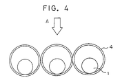
- the ring fins 4 deflects the currents of the air so that the air is able to reach the rear portions having a low heat-transfer coefficient on the lower side of the heat transfer tubes 1. Consequently, heat transfer is promoted and the heat exchanger transfers heat at a high heat-transfer rate. Since the transversely adjacent ring fins 4 cross each other and joined together at crossing points 8a and 8b, the heat-transfer suface has a firm construction, the heat transfer tubes 1 can be arranged at comparatively small intervals, and the heat exchanger has a comparatively large heat-transfer area.
- the inside diameter of the ring fins 4 is greater than the outside diameter of the heat-transfer tubes 1, comparatively large spaces are formed between the ring fins 4 and the heat-transfer tubes 1. Therefore, condensed water droplets are hardly able to stay on the heat exchanger even if the heat exchanger is used in a moist atmosphere where moisture contained in the atmosphere condenses in water droplets, the heat exchanger is hardly clogged with condensed water droplets and reduction in heat exchanging quantity due to reduction in the flow of the air can be suppressed.
- the coil ring fin 5 is formed by helically connecting of ring fins, it can comparatively easiliy be formed and be firm and strong. Mechanisms of this embodiment effective in promoting heat transfer are the same as those of the first embodiment and hence the description thereof will be omitted.
- FIG. 11 showing a heat exchanger for an air conditioner
- heat-transfer tubes 1 and coil ring fins 4 which is similar to those of the first to the fifth embodiment.
- the inside diameter of the ring fins 4 is greater than the outside diameter of the heat-transfer tubes 1.
- Portions of inner surfaces of each ring fin 4 is attached to the outer surfaces of the three heat-transfer tubes 1.
- heat-transfer tubes 1 are arranged at predetermined intervals, and ring fins 4, i.e., heat-transfer fins, having an inside diameter greater than the outside diameter of the heat-transfer tube 1 are attached to the heat-transfer tube 1 so as to extend obliquely downward.
- An external fluid such as air, flows in the direction of the arrow A.
Landscapes
- Engineering & Computer Science (AREA)
- Physics & Mathematics (AREA)
- Mechanical Engineering (AREA)
- Geometry (AREA)
- Thermal Sciences (AREA)
- General Engineering & Computer Science (AREA)
- Heat-Exchange Devices With Radiators And Conduit Assemblies (AREA)
- Air Filters, Heat-Exchange Apparatuses, And Housings Of Air-Conditioning Units (AREA)
Claims (10)
- Echangeur de chaleur comprenant :une pluralité de tubes de transmission de chaleur (1) arrangés en parallèle les uns par rapport aux autres à des intervalles prédéterminés, etun moyen formant ailettes, caractérisé en ce que le moyen formant ailettes comprend une pluralité d'ailettes annulaires (4) faites d'un fil fin, ayant une forme pratiquement circulaire d'un diamètre plus grand que le diamètre extérieur des tubes de transmission de chaleur (1), et chacune ayant une portion de la circonférence intérieure fixée à la surface extérieure du tube de transmission de chaleur (1),les centres respectifs des premières ailettes annulaires (4) sont décalés par rapport aux axes centraux des tubes de transmission de chaleur (1) vers le côté supérieur, par référence à la direction de l'écoulement d'un fluide extérieur qui, en fonctionnement, s'écoule dans une direction allant vers les tubes de transmission de chaleur (1).
- Echangeur de chaleur selon la revendication 1, dans lequel le moyen formant ailettes comprend des premières ailettes annulaires adjacentes (4) qui sont en contact entre elles et réunies entre elles au moins en une position.
- Echangeur de chaleur selon la revendication 1, dans lequel le moyen formant ailettes comprend une pluralité de deuxièmes ailettes annulaires (4a) d'un diamètre plus grand que le diamètre extérieur des tubes de transmission de chaleur (1), chacune ayant une portion de la circonférence intérieure fixée à la surface extérieure du tube de transmission de chaleur (1), les deuxièmes ailettes annulaires (4a) disposées avec leurs centres décalés par rapport aux axes centraux des tubes de transmission de chaleur (1) vers le côté inférieur par référence à la direction de l'écoulement du fluide extérieur qui s'écoule à l'extérieur des tubes de transmission de chaleur (1) ; et
les premières (4b) et les deuxièmes (4a) ailettes annulaires sont arrangées en alternance le long de l'axe de chaque tube de transmission de chaleur (1). - Echangeur de chaleur selon la revendication 1 ou 2, dans lequel chaque ailette annulaire (4) est une ailette annulaire en forme de 8 ayant deux boucles, et le tube de transmission de chaleur (1) est inséré dans une des deux boucles.
- Echangeur de chaleur selon la revendication 1, dans lequel le moyen formant ailettes comprend des premières ailettes annulaires qui sont formées par une pluralité de premiers anneaux (5) en forme d'enroulement formés en enroulant des fils fins en hélice, et le pas des premiers anneaux (5) en forme d'enroulement est le double du diamètre du fil fin ou plus grand.
- Echangeur de chaleur selon la revendication 5, dans lequel les premières ailettes (5) en forme d'enroulement sont en contact entre elles et fixées les unes aux autres au moins en une position.
- Echangeur de chaleur selon la revendication 5, dans lequel le moyen formant ailettes comprend des deuxièmes anneaux (5a) en forme d'enroulement formés par des deuxièmes ailettes annulaires reliées entre elles en hélice dans une forme pratiquement circulaire ayant un diamètre plus grand que le diamètre extérieur des tubes de transmission de chaleur (1) et chacune ayant une portion de la circonférence intérieure fixée à la surface extérieure du tube de transmission de chaleur (1), de sorte que les centres des ailettes annulaires sont décalés par rapport aux axes centraux des tubes de transmission de chaleur vers le côté inférieur, par référence à la direction de l'écoulement du fluide extérieur qui s'écoule à l'extérieur des tubes de transmission de chaleur (1).
- Echangeur de chaleur selon une quelconque des revendications 5 à 7, dans lequel une pluralité de tubes de transmission de chaleur (1) sont insérés dans chaque anneau (5) en forme d'enroulement et fixés à la circonférence intérieure de l'anneau (5) en forme d'enroulement respectif.
- Echangeur de chaleur selon une quelconque des revendications 1 à 7, dans lequel des portions des circonférences intérieures des ailettes annulaires (4, 5) sont fixées aux tubes de transmission de chaleur (1) de manière que les ailettes annulaires (4, 5) s'étendent obliquement vers le bas.
- Echangeur de chaleur selon une quelconque des revendications 1 à 9, dans lequel l'échangeur de chaleur est équipé d'une pluralité d'éléments de transmission de chaleur dont chacun comprend la pluralité de tubes de transmission de chaleur (1) dans lesquels circule un milieu de refroidissement et la pluralité d'ailettes annulaires, arrangées en parallèle entre elles le long de, et perpendiculairement à, la direction d'écoulement d'un fluide extérieur qui s'écoule à l'extérieur des tubes de transmission de chaleur (1) et reliées entre elles, le milieu de refroidissement, en fonctionnement, s'écoule de l'élément de transmission de chaleur disposé dans la position extrême inférieure, par référence à la direction d'écoulement du fluide extérieur, séquentiellement à travers les éléments de transmission de chaleur, vers l'élément de transmission de chaleur disposé dans la position extrême supérieure, par référence à la direction de l'écoulement du fluide extérieur.
Applications Claiming Priority (7)
| Application Number | Priority Date | Filing Date | Title |
|---|---|---|---|
| JP17130794 | 1994-07-22 | ||
| JP17130794 | 1994-07-22 | ||
| JP171307/94 | 1994-07-22 | ||
| JP258351/94 | 1994-10-24 | ||
| JP25835194 | 1994-10-24 | ||
| JP25835194 | 1994-10-24 | ||
| EP95104993A EP0693666B1 (fr) | 1994-07-22 | 1995-04-04 | Echangeur de chaleur pour un appareil de conditionnement d'air |
Related Parent Applications (1)
| Application Number | Title | Priority Date | Filing Date |
|---|---|---|---|
| EP95104993A Division EP0693666B1 (fr) | 1994-07-22 | 1995-04-04 | Echangeur de chaleur pour un appareil de conditionnement d'air |
Publications (2)
| Publication Number | Publication Date |
|---|---|
| EP0860674A1 EP0860674A1 (fr) | 1998-08-26 |
| EP0860674B1 true EP0860674B1 (fr) | 2000-06-28 |
Family
ID=26494074
Family Applications (4)
| Application Number | Title | Priority Date | Filing Date |
|---|---|---|---|
| EP95104993A Expired - Lifetime EP0693666B1 (fr) | 1994-07-22 | 1995-04-04 | Echangeur de chaleur pour un appareil de conditionnement d'air |
| EP98108086A Expired - Lifetime EP0862037B1 (fr) | 1994-07-22 | 1995-04-04 | Echangeur de chaleur |
| EP98108085A Expired - Lifetime EP0860674B1 (fr) | 1994-07-22 | 1995-04-04 | Echangeur de chaleur |
| EP98108087A Expired - Lifetime EP0864835B1 (fr) | 1994-07-22 | 1995-04-04 | Echangeur de chaleur |
Family Applications Before (2)
| Application Number | Title | Priority Date | Filing Date |
|---|---|---|---|
| EP95104993A Expired - Lifetime EP0693666B1 (fr) | 1994-07-22 | 1995-04-04 | Echangeur de chaleur pour un appareil de conditionnement d'air |
| EP98108086A Expired - Lifetime EP0862037B1 (fr) | 1994-07-22 | 1995-04-04 | Echangeur de chaleur |
Family Applications After (1)
| Application Number | Title | Priority Date | Filing Date |
|---|---|---|---|
| EP98108087A Expired - Lifetime EP0864835B1 (fr) | 1994-07-22 | 1995-04-04 | Echangeur de chaleur |
Country Status (8)
| Country | Link |
|---|---|
| US (3) | US5769157A (fr) |
| EP (4) | EP0693666B1 (fr) |
| KR (1) | KR100222015B1 (fr) |
| CN (1) | CN1062952C (fr) |
| AU (2) | AU694706B2 (fr) |
| DE (4) | DE69519445T2 (fr) |
| ES (4) | ES2152111T3 (fr) |
| MY (2) | MY115441A (fr) |
Families Citing this family (27)
| Publication number | Priority date | Publication date | Assignee | Title |
|---|---|---|---|---|
| US5806585A (en) * | 1995-02-27 | 1998-09-15 | Mitsubishi Denki Kabushiki Kaisha | Heat exchanger, refrigeration system, air conditioner, and method and apparatus for fabricating heat exchanger |
| JPH08270973A (ja) * | 1995-03-30 | 1996-10-18 | Mitsubishi Electric Corp | 空気調和機 |
| JPH09296994A (ja) * | 1996-04-30 | 1997-11-18 | Sanden Corp | 熱交換器 |
| EP1301259A1 (fr) * | 2000-07-17 | 2003-04-16 | August Schmid-Stiftung Zürich | Dispositif filtrant destine notamment a un liquide |
| DE10141490A1 (de) * | 2001-08-24 | 2003-03-13 | Behr Gmbh & Co | Kühler und Verfahren zum Kühlen eines Mediums |
| US6892803B2 (en) * | 2002-11-19 | 2005-05-17 | Modine Manufacturing Company | High pressure heat exchanger |
| US6959758B2 (en) * | 2002-12-03 | 2005-11-01 | Modine Manufacturing Company | Serpentine tube, cross flow heat exchanger construction |
| US7140426B2 (en) * | 2003-08-29 | 2006-11-28 | Plascore, Inc. | Radiant panel |
| EP1707912A1 (fr) * | 2005-04-01 | 2006-10-04 | Fiwihex B.V. | Echangeur de chaleur et serre |
| NL1029280C1 (nl) * | 2005-06-17 | 2006-12-19 | Fiwihex B V | Behuizing met een koeling. |
| JP4852981B2 (ja) * | 2005-11-02 | 2012-01-11 | 株式会社ノーリツ | 温水装置 |
| KR100739196B1 (ko) * | 2006-01-04 | 2007-07-13 | 엘지전자 주식회사 | 핀-튜브 열교환기 |
| DE102006022629A1 (de) * | 2006-05-12 | 2007-11-15 | Spörl KG | Wärmetauschvorrichtung für einen Wärmeaustausch zwischen Medien und Webstruktur |
| EP2110633A1 (fr) * | 2007-01-31 | 2009-10-21 | Shi Mechanical & Equipment Inc. | Échangeur de chaleur de type tube à ailettes en spirale |
| FI125709B (fi) * | 2007-08-31 | 2016-01-15 | Retermia Oy | Laitteisto ja menetelmä neularipaputken teossa ja neularipaputki |
| US20100122806A1 (en) * | 2008-11-14 | 2010-05-20 | Nordyne Inc. | Compact and Efficient Heat Exchanger, Furnace, HVAC Unit, Building, and Method of Making |
| PL221028B1 (pl) | 2011-06-24 | 2016-02-29 | Aic Spółka Akcyjna | Pakiet rurowy wymiennika ciepła |
| CN104040254B (zh) * | 2011-12-21 | 2016-09-21 | 山特维克知识产权股份有限公司 | 包括辐射元件的蒸汽锅炉 |
| WO2016144276A1 (fr) * | 2015-03-11 | 2016-09-15 | Atm Beyaz Eşya Parçalari Sanayi̇ Ve Ti̇caret Li̇mi̇ted Şi̇rketi̇ | Échangeur de chaleur étagé, relié en série et son procédé de fabrication |
| US11480398B2 (en) * | 2015-05-22 | 2022-10-25 | The Johns Hopkins University | Combining complex flow manifold with three dimensional woven lattices as a thermal management unit |
| US10982913B2 (en) * | 2015-05-22 | 2021-04-20 | The Johns Hopkins University | Three dimensional woven lattices as multi-functional heat exchanger |
| US10422586B2 (en) | 2015-11-10 | 2019-09-24 | Hamilton Sundstrand Corporation | Heat exchanger |
| DE102016224338A1 (de) * | 2016-12-07 | 2018-06-07 | Fraunhofer-Gesellschaft zur Förderung der angewandten Forschung e.V. | Wärmeübertrager und Verfahren zu dessen Verwendung |
| CN112771342B (zh) * | 2018-10-05 | 2022-12-16 | 三菱电机株式会社 | 热交换器及制冷循环装置 |
| KR102681026B1 (ko) * | 2019-03-29 | 2024-07-04 | 한온시스템 주식회사 | 열교환기 |
| US12601547B2 (en) * | 2023-05-10 | 2026-04-14 | Rtx Corporation | Extruded connected microtube and heat exchanger |
| TWI866683B (zh) * | 2023-12-08 | 2024-12-11 | 緯創資通股份有限公司 | 可撓式散熱器 |
Family Cites Families (26)
| Publication number | Priority date | Publication date | Assignee | Title |
|---|---|---|---|---|
| FR748179A (fr) * | 1932-07-28 | 1933-06-29 | Perfectionnements à la construction de tubes de transmission de chaleur | |
| FR793344A (fr) * | 1934-10-24 | 1936-01-22 | échangeur thermique | |
| DE654158C (de) * | 1934-10-24 | 1937-12-14 | Henry Dieterlen | Waermeaustauscher |
| DE851203C (de) * | 1939-06-04 | 1952-10-02 | Siemens Ag | Rohrfoermiger Waermeaustauscher, insbesondere Kondensator fuer Kaeltemaschinen |
| US2588500A (en) * | 1945-08-18 | 1952-03-11 | Hugh C Dugan | Process for making heat exchangers |
| US2500501A (en) * | 1946-09-12 | 1950-03-14 | Kellogg M W Co | Method of making heat exchangers |
| GB636615A (en) * | 1947-07-03 | 1950-05-03 | Gen Electric Co Ltd | Improvements in and relating to heat-exchangers for exchanging heat between a solid surface and a fluid |
| US2469635A (en) * | 1948-01-03 | 1949-05-10 | Svenska Maskinverken Ab | Steam boiler or the like having extended heat transfer surfaces |
| DE975537C (de) * | 1948-04-28 | 1962-01-11 | Svenska Maskinverken Ab | Waermeaustauscher |
| FR1017029A (fr) * | 1949-06-25 | 1952-11-28 | Air Preheater | Procédé pour la fixation d'ailettes en forme de broches à des éléments tubulaires d'échangeurs de chaleur |
| US2620170A (en) * | 1950-08-18 | 1952-12-02 | United States Steel Corp | Heat transfer unit |
| US2952906A (en) * | 1956-08-17 | 1960-09-20 | Reynolds Metals Co | Method of soldering aluminum to copper or brass |
| DE1132883B (de) * | 1957-01-30 | 1962-07-12 | Franciscus Roffelsen | Verfahren zum Herstellung von Waermeaustauschelementen |
| GB976003A (en) * | 1962-07-13 | 1964-11-25 | Reiert Aluminium Metall | A heat exchanger |
| FR2045742B1 (fr) * | 1969-06-30 | 1974-02-22 | Chausson Usines Sa | |
| US4056143A (en) * | 1972-11-08 | 1977-11-01 | The Plessey Company Limited | Heat exchange apparatus |
| FR2428224A2 (fr) * | 1978-06-06 | 1980-01-04 | Martel Catala & Cie Ets | Perfectionnements aux faisceaux tubulaires et a leur procede de fabrication |
| JPS5730583A (en) * | 1980-07-29 | 1982-02-18 | Muneyuki Sakamoto | Selecting method in line transportation |
| DE3309923C2 (de) * | 1983-03-19 | 1985-10-31 | Rolf Dipl.-Ing. 4100 Duisburg Bähr | Wärmetauscher |
| JPS61153388A (ja) * | 1984-12-26 | 1986-07-12 | Kawasaki Steel Corp | 熱交換装置 |
| JPS61153389A (ja) * | 1984-12-26 | 1986-07-12 | Kawasaki Steel Corp | 熱交換装置の流体変向装置 |
| JPS61181970A (ja) * | 1985-02-07 | 1986-08-14 | Hitachi Cable Ltd | 光フアイバを用いた分散位置におけるセンシング方式 |
| JPS6415087A (en) * | 1987-07-08 | 1989-01-19 | Nippi Kikai Kk | Taking-in apparatus for leather and the like |
| JPH0236781A (ja) * | 1988-07-22 | 1990-02-06 | Mitsubishi Electric Corp | 電気機器の押釦制御装置 |
| JPH05133691A (ja) * | 1991-11-08 | 1993-05-28 | Daikin Ind Ltd | 熱交換器およびその製造方法 |
| JPH0650689A (ja) * | 1992-07-30 | 1994-02-25 | Sharp Corp | 熱交換器およびその製造方法ならびに金属製管路と金属製線材との接続方法 |
-
1995
- 1995-04-04 EP EP95104993A patent/EP0693666B1/fr not_active Expired - Lifetime
- 1995-04-04 EP EP98108086A patent/EP0862037B1/fr not_active Expired - Lifetime
- 1995-04-04 DE DE69519445T patent/DE69519445T2/de not_active Expired - Lifetime
- 1995-04-04 DE DE69510504T patent/DE69510504T2/de not_active Expired - Lifetime
- 1995-04-04 ES ES98108087T patent/ES2152111T3/es not_active Expired - Lifetime
- 1995-04-04 ES ES95104993T patent/ES2135614T3/es not_active Expired - Lifetime
- 1995-04-04 ES ES98108085T patent/ES2149030T3/es not_active Expired - Lifetime
- 1995-04-04 DE DE69523639T patent/DE69523639T2/de not_active Expired - Lifetime
- 1995-04-04 US US08/417,159 patent/US5769157A/en not_active Expired - Lifetime
- 1995-04-04 DE DE69517710T patent/DE69517710T2/de not_active Expired - Lifetime
- 1995-04-04 EP EP98108085A patent/EP0860674B1/fr not_active Expired - Lifetime
- 1995-04-04 EP EP98108087A patent/EP0864835B1/fr not_active Expired - Lifetime
- 1995-04-04 ES ES98108086T patent/ES2165111T3/es not_active Expired - Lifetime
- 1995-04-25 CN CN95104783A patent/CN1062952C/zh not_active Expired - Fee Related
- 1995-07-11 KR KR1019950020258A patent/KR100222015B1/ko not_active Expired - Fee Related
- 1995-07-17 MY MYPI95002015A patent/MY115441A/en unknown
- 1995-07-17 MY MYPI20022866A patent/MY134032A/en unknown
-
1996
- 1996-06-06 US US08/659,763 patent/US5822854A/en not_active Expired - Lifetime
-
1997
- 1997-10-24 AU AU42827/97A patent/AU694706B2/en not_active Ceased
- 1997-10-24 AU AU42828/97A patent/AU694707B2/en not_active Ceased
-
1998
- 1998-02-10 US US09/021,343 patent/US5964284A/en not_active Expired - Lifetime
Also Published As
Similar Documents
| Publication | Publication Date | Title |
|---|---|---|
| EP0860674B1 (fr) | Echangeur de chaleur | |
| EP0881448B1 (fr) | Tube plat à passages multiples pour échangeur de chaleur et échangeur de chaleur utilisant de tels tubes | |
| US7913750B2 (en) | Louvered air center with vortex generating extensions for compact heat exchanger | |
| KR950007282B1 (ko) | 세분된 유로를 구비한 콘덴서 | |
| EP1540262B1 (fr) | Ailette d'echangeur thermique a crevees inclinees | |
| US4580623A (en) | Heat exchanger | |
| US20110036550A1 (en) | Fin and heat exchanger having the same | |
| US20070199686A1 (en) | Heat exchanger | |
| US4715437A (en) | Heat exchanger | |
| CN104833137A (zh) | 热交换器 | |
| JP3264525B2 (ja) | 熱交換器 | |
| US8196646B2 (en) | Heat exchanger assembly | |
| EP4300026B1 (fr) | Ailette d'échange de chaleur, échangeur de chaleur et système de pompe à chaleur | |
| JP6377628B2 (ja) | フィン付きのチューブ要素、その製造方法およびフィン付きのチューブ要素を備えた熱交換器 | |
| JPH0755380A (ja) | 熱交換器 | |
| JPH01310297A (ja) | 熱交換器用プレートフィン及びフィンチューブ型熱交換器 | |
| CN212457513U (zh) | 换热器、空调器 | |
| CN109668468B (zh) | 翅片组件、微通道换热器及空调器 | |
| KR100941706B1 (ko) | 열 교환기 | |
| JP4513207B2 (ja) | 空気熱交換器 | |
| JP2001141382A (ja) | 空気熱交換器 | |
| HK1006657B (en) | Heat exchanger for an air conditioner | |
| KR100484912B1 (ko) | 열교환기 | |
| KR100502295B1 (ko) | 열교환기 | |
| JPS6152589A (ja) | 空気用熱交換器 |
Legal Events
| Date | Code | Title | Description |
|---|---|---|---|
| PUAI | Public reference made under article 153(3) epc to a published international application that has entered the european phase |
Free format text: ORIGINAL CODE: 0009012 |
|
| 17P | Request for examination filed |
Effective date: 19980504 |
|
| AC | Divisional application: reference to earlier application |
Ref document number: 693666 Country of ref document: EP |
|
| AK | Designated contracting states |
Kind code of ref document: A1 Designated state(s): BE DE ES FR GB IT |
|
| 17Q | First examination report despatched |
Effective date: 19990125 |
|
| GRAG | Despatch of communication of intention to grant |
Free format text: ORIGINAL CODE: EPIDOS AGRA |
|
| GRAG | Despatch of communication of intention to grant |
Free format text: ORIGINAL CODE: EPIDOS AGRA |
|
| GRAH | Despatch of communication of intention to grant a patent |
Free format text: ORIGINAL CODE: EPIDOS IGRA |
|
| GRAH | Despatch of communication of intention to grant a patent |
Free format text: ORIGINAL CODE: EPIDOS IGRA |
|
| GRAA | (expected) grant |
Free format text: ORIGINAL CODE: 0009210 |
|
| AC | Divisional application: reference to earlier application |
Ref document number: 693666 Country of ref document: EP |
|
| AK | Designated contracting states |
Kind code of ref document: B1 Designated state(s): BE DE ES FR GB IT |
|
| REF | Corresponds to: |
Ref document number: 69517710 Country of ref document: DE Date of ref document: 20000803 |
|
| ET | Fr: translation filed | ||
| ITF | It: translation for a ep patent filed | ||
| REG | Reference to a national code |
Ref country code: ES Ref legal event code: FG2A Ref document number: 2149030 Country of ref document: ES Kind code of ref document: T3 |
|
| PLBE | No opposition filed within time limit |
Free format text: ORIGINAL CODE: 0009261 |
|
| STAA | Information on the status of an ep patent application or granted ep patent |
Free format text: STATUS: NO OPPOSITION FILED WITHIN TIME LIMIT |
|
| 26N | No opposition filed | ||
| REG | Reference to a national code |
Ref country code: GB Ref legal event code: IF02 |
|
| PGFP | Annual fee paid to national office [announced via postgrant information from national office to epo] |
Ref country code: ES Payment date: 20120424 Year of fee payment: 18 |
|
| PGFP | Annual fee paid to national office [announced via postgrant information from national office to epo] |
Ref country code: DE Payment date: 20130327 Year of fee payment: 19 Ref country code: BE Payment date: 20130415 Year of fee payment: 19 |
|
| PGFP | Annual fee paid to national office [announced via postgrant information from national office to epo] |
Ref country code: FR Payment date: 20130625 Year of fee payment: 19 |
|
| PGFP | Annual fee paid to national office [announced via postgrant information from national office to epo] |
Ref country code: IT Payment date: 20130423 Year of fee payment: 19 |
|
| PGFP | Annual fee paid to national office [announced via postgrant information from national office to epo] |
Ref country code: GB Payment date: 20140402 Year of fee payment: 20 |
|
| REG | Reference to a national code |
Ref country code: DE Ref legal event code: R119 Ref document number: 69517710 Country of ref document: DE |
|
| REG | Reference to a national code |
Ref country code: DE Ref legal event code: R119 Ref document number: 69517710 Country of ref document: DE Effective date: 20141101 |
|
| REG | Reference to a national code |
Ref country code: FR Ref legal event code: ST Effective date: 20141231 |
|
| PG25 | Lapsed in a contracting state [announced via postgrant information from national office to epo] |
Ref country code: DE Free format text: LAPSE BECAUSE OF NON-PAYMENT OF DUE FEES Effective date: 20141101 |
|
| PG25 | Lapsed in a contracting state [announced via postgrant information from national office to epo] |
Ref country code: FR Free format text: LAPSE BECAUSE OF NON-PAYMENT OF DUE FEES Effective date: 20140430 |
|
| PG25 | Lapsed in a contracting state [announced via postgrant information from national office to epo] |
Ref country code: IT Free format text: LAPSE BECAUSE OF NON-PAYMENT OF DUE FEES Effective date: 20140404 |
|
| REG | Reference to a national code |
Ref country code: GB Ref legal event code: PE20 Expiry date: 20150403 |
|
| REG | Reference to a national code |
Ref country code: ES Ref legal event code: FD2A Effective date: 20150528 |
|
| PG25 | Lapsed in a contracting state [announced via postgrant information from national office to epo] |
Ref country code: ES Free format text: LAPSE BECAUSE OF NON-PAYMENT OF DUE FEES Effective date: 20140405 Ref country code: GB Free format text: LAPSE BECAUSE OF EXPIRATION OF PROTECTION Effective date: 20150403 |
|
| PG25 | Lapsed in a contracting state [announced via postgrant information from national office to epo] |
Ref country code: BE Free format text: LAPSE BECAUSE OF NON-PAYMENT OF DUE FEES Effective date: 20140430 |