EP0860689A2 - Kühlung von Gasturbinenleitschaufeln - Google Patents
Kühlung von Gasturbinenleitschaufeln Download PDFInfo
- Publication number
- EP0860689A2 EP0860689A2 EP98300983A EP98300983A EP0860689A2 EP 0860689 A2 EP0860689 A2 EP 0860689A2 EP 98300983 A EP98300983 A EP 98300983A EP 98300983 A EP98300983 A EP 98300983A EP 0860689 A2 EP0860689 A2 EP 0860689A2
- Authority
- EP
- European Patent Office
- Prior art keywords
- cooling
- air
- steam
- shroud
- flow path
- Prior art date
- Legal status (The legal status is an assumption and is not a legal conclusion. Google has not performed a legal analysis and makes no representation as to the accuracy of the status listed.)
- Granted
Links
Images


Classifications
-
- F—MECHANICAL ENGINEERING; LIGHTING; HEATING; WEAPONS; BLASTING
- F01—MACHINES OR ENGINES IN GENERAL; ENGINE PLANTS IN GENERAL; STEAM ENGINES
- F01D—NON-POSITIVE DISPLACEMENT MACHINES OR ENGINES, e.g. STEAM TURBINES
- F01D5/00—Blades; Blade-carrying members; Heating, heat-insulating, cooling or antivibration means on the blades or the members
- F01D5/12—Blades
- F01D5/14—Form or construction
- F01D5/18—Hollow blades, i.e. blades with cooling or heating channels or cavities; Heating, heat-insulating or cooling means on blades
- F01D5/187—Convection cooling
-
- F—MECHANICAL ENGINEERING; LIGHTING; HEATING; WEAPONS; BLASTING
- F05—INDEXING SCHEMES RELATING TO ENGINES OR PUMPS IN VARIOUS SUBCLASSES OF CLASSES F01-F04
- F05D—INDEXING SCHEME FOR ASPECTS RELATING TO NON-POSITIVE-DISPLACEMENT MACHINES OR ENGINES, GAS-TURBINES OR JET-PROPULSION PLANTS
- F05D2240/00—Components
- F05D2240/80—Platforms for stationary or moving blades
- F05D2240/81—Cooled platforms
-
- F—MECHANICAL ENGINEERING; LIGHTING; HEATING; WEAPONS; BLASTING
- F05—INDEXING SCHEMES RELATING TO ENGINES OR PUMPS IN VARIOUS SUBCLASSES OF CLASSES F01-F04
- F05D—INDEXING SCHEME FOR ASPECTS RELATING TO NON-POSITIVE-DISPLACEMENT MACHINES OR ENGINES, GAS-TURBINES OR JET-PROPULSION PLANTS
- F05D2260/00—Function
- F05D2260/20—Heat transfer, e.g. cooling
- F05D2260/201—Heat transfer, e.g. cooling by impingement of a fluid
-
- F—MECHANICAL ENGINEERING; LIGHTING; HEATING; WEAPONS; BLASTING
- F05—INDEXING SCHEMES RELATING TO ENGINES OR PUMPS IN VARIOUS SUBCLASSES OF CLASSES F01-F04
- F05D—INDEXING SCHEME FOR ASPECTS RELATING TO NON-POSITIVE-DISPLACEMENT MACHINES OR ENGINES, GAS-TURBINES OR JET-PROPULSION PLANTS
- F05D2260/00—Function
- F05D2260/20—Heat transfer, e.g. cooling
- F05D2260/202—Heat transfer, e.g. cooling by film cooling
-
- F—MECHANICAL ENGINEERING; LIGHTING; HEATING; WEAPONS; BLASTING
- F05—INDEXING SCHEMES RELATING TO ENGINES OR PUMPS IN VARIOUS SUBCLASSES OF CLASSES F01-F04
- F05D—INDEXING SCHEME FOR ASPECTS RELATING TO NON-POSITIVE-DISPLACEMENT MACHINES OR ENGINES, GAS-TURBINES OR JET-PROPULSION PLANTS
- F05D2260/00—Function
- F05D2260/20—Heat transfer, e.g. cooling
- F05D2260/221—Improvement of heat transfer
- F05D2260/2212—Improvement of heat transfer by creating turbulence
-
- F—MECHANICAL ENGINEERING; LIGHTING; HEATING; WEAPONS; BLASTING
- F05—INDEXING SCHEMES RELATING TO ENGINES OR PUMPS IN VARIOUS SUBCLASSES OF CLASSES F01-F04
- F05D—INDEXING SCHEME FOR ASPECTS RELATING TO NON-POSITIVE-DISPLACEMENT MACHINES OR ENGINES, GAS-TURBINES OR JET-PROPULSION PLANTS
- F05D2260/00—Function
- F05D2260/20—Heat transfer, e.g. cooling
- F05D2260/232—Heat transfer, e.g. cooling characterized by the cooling medium
- F05D2260/2322—Heat transfer, e.g. cooling characterized by the cooling medium steam
Definitions
- the present invention relates to a stationary blade for a gas turbine in which cooling is effected by using both steam and air as cooling media.
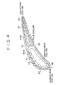
- FIG. 4 is a sectional view of a conventional cooled stationary blade for gas turbine.
- a cooled stationary blade 51 is integrally formed together with outside and inside shrouds (not shown) by precision casting. Inserts 54A and 54B having many cooling holes 53 are inserted in the cooled stationary blade 51, and cooling air is supplied into the inserts 54A and 54B through the outside shroud.
- the cooling air flows out through the cooling holes 53 as indicated by arrows, and flows into a hollow chamber A after effecting impingement cooling by colliding with the inner wall of the cooled stationary blade 51. Subsequently, the cooling air cools the cooled stationary blade 51 while flowing toward the trailing edge of blade. Part of the cooling air forms a cooling film on the blade surface by flowing out through film cooling holes 52 and 55 and flowing along the blade profile, whereby film cooling is effected.
- the cooling air flowing out through a slit 56 at the blade trailing edge convection-cools the blade trailing edge including pin fins 57. Also, the cooling air flowing out through a cooling hole 58 at the blade leading edge shower-cools the blade leading edge.
- the outside and inside shrouds are provided with an impingement plate and pin fins, and impingement cooling and pin fin cooling are effected by the cooling air before it is supplied to the inserts 54A and 54B.
- the cooling medium passage must be closed to the outside and have supply and recovery ports of steam.
- the present invention was made in view of this situation, and accordingly an object thereof is to provide a gas turbine stationary blade in which every necessary place is cooled by effectively using both cooling media of steam and air in a well-balanced manner, and the cooling steam is used without leakage.
- the present invention for solving the above problems provides a gas turbine stationary blade provided with a steam cooling section at the rear from the leading edge of blade and an air cooling section at the trailing edge of blade, in which the steam cooling section comprises a cooling steam supply portion having an impingement plate, which is formed at the end of an outside shroud; a serpentine flow path extending in the blade length direction from the cooling steam supply portion and turns plural times; many turbulators arranged on the inner wall of the serpentine flow path so as to extend slantwise with respect to the flow; an inside impingement plate provided in an inside shroud at the final turning portion of the serpentine flow path; and a steam recovery port formed in the outside shroud at a downstream position of the serpentine flow path turned at the inside impingement plate, and the air cooling section comprises an air flow path extending at the rear of the steam cooling section from the outer edge of the outside shroud to the outer edge of the inside shroud and having many turbulators arranged on the inner wall so as to extend slantwise with
- the cooling steam cools the portion at the rear from the blade leading edge with a higher temperature.
- the cooling steam impingement-cools the outside shroud, and then cools the blade while flowing in the serpentine flow path in the lengthwise direction in a turbulent flow state by being turned. It impingement-cools the inside shroud during the flow, and is finally transferred to a predetermined recovery system from the outside shroud.
- the cooling air cools the trailing edge portion of blade.
- the cooling air flows in the air flow path in the blade length direction in a turbulent flow state to cool the blade, and effects slot cooling in which the cooling air passes through the slot holes to the gas flow path at the trailing edge of blade.
- Desirable blade cooling is effected by the cooperation of steam cooling and air cooling, and in steam cooling, the cooling steam is guided without leakage during the cooling process and recovered surely in a predetermined manner, by which the efficiency is improved variously.
- the gas turbine stationary blade is provided with a steam cooling section at the rear from the leading edge of blade and an air cooling section at the trailing edge of blade.
- the steam cooling section comprises a cooling steam supply portion having an impingement plate, which is formed at the end of an outside shroud; a serpentine flow path extending in the blade length direction from the cooling steam supply portion and turns plural times; many turbulators arranged on the inner wall of the serpentine flow path so as to extend slantwise with respect to the flow; an inside impingement plate provided in an inside shroud at the final turning portion of the serpentine flow path; and a steam recovery port formed in the outside shroud at a downstream position of the serpentine flow path turned at the inside impingement plate.
- the air cooling section comprises an air flow path extending at the rear of the steam cooling section from the outer edge of the outside shroud to the outer edge of the inside shroud and having many turbulators arranged on the inner wall so as to extend slantwise with respect to the flow; slot holes provided at the trailing edge of blade; and a cooling air supply portion for supplying the cooling air to the slot holes.
- the gas turbine stationary blade configured as described above has the following effects.
- the gas turbine stationary blade which has a high temperature in operation, is cooled by both of the steam cooling section and air cooling section.
- the cooling steam flows in the serpentine flow path in the blade at the rear from the leading edge while impingement-cooling the outside and inside shrouds.
- the air cooling section the air flow path cooling and slot cooling are combined at the trailing edge.
- the heated cooling steam is recovered surely and reused.
- steam has a high heat capacity, the total fluid flow of steam plus air is significantly decreased as compared with the case where cooling is effected by air only. Further, a great decrease in use of air as a cooling medium provides a margin for combustion air, resulting in the improvement in gas turbine efficiency.
- FIG. 1 is a sectional view of a cooled stationary blade for a gas turbine
- FIG. 2 is a plan view of an outside shroud
- FIG. 3 is a plan view of an inside shroud.
- Reference numeral 1 denotes a gas turbine stationary blade
- 3 denotes a serpentine flow path formed in the stationary blade 1.
- the serpentine flow path 3 is named because it extends in the lengthwise direction of the stationary blade 1 and lies in a zigzag line by turning on the outer and inner peripheral sides.
- turbulators 2 projecting from the inner wall of serpentine flow path 3 are provided at predetermined intervals over almost the entire region of the serpentine flow path 3.
- the turbulators 2 extend in such a direction as to slantwise intersect the flow direction of fluid flowing in the serpentine flow path 3 and are arranged substantially in parallel with each other.
- the fluid flowing in the serpentine flow path 3 collides with the turbulators 2 on the inner peripheral surface so that a turbulent flow is produced, preventing the formation of a laminar flow state which has a poor heat transfer.
- An outside shroud 4 is formed integrally with the end portion of the stationary blade 1 on the outside with the turbine rotation shaft being the center.
- An impingement plate 5 formed with many holes (not shown) is provided in the outside shroud 4 to impingement-cool the cooling steam supplied through a steam supply port 20 toward the outside shroud 4.
- An inside shroud 6 is formed integrally on the inside in the radial direction of the stationary blade 1 so as to lie opposite to the outside shroud 4.
- An inside impingement plate 7 is provided in the inside shroud 6 to impingement-cool the inside shroud 6 by supplying the cooling steam at the final turning portion of the serpentine flow path 3 and ejecting the cooling steam through many holes (not shown).
- a steam recovery port 21 is provided in the outside shroud 4 to form an outlet for delivering the cooling steam flowing out of the end of the serpentine flow path 3 to an external recovery system (not shown).
- a steam cooling section is formed by a series of related structures ranging from the aforesaid steam supply port 20 to this steam recovery port 21.
- a trailing edge 8 of the stationary blade 1 is formed with many slot holes 9 distributed in the blade length direction, though not shown clearly in the figure.
- An air flow path 10 for supplying the cooling air is provided at the rear of the serpentine flow path 3 of the steam cooling section and in front of the slot holes 9.
- the inner wall of the air flow path 10 is provided with many turbulators 2a extending slantwise with respect to the flow of cooling air.
- An air supply port 22 of the air flow path 10 is formed at the outer edge of the outside shroud 4, and the air flow path 10 extends to the outer edge of the inside shroud 6.
- air flow paths 13 and 16 are arranged, respectively, so as to surround the outer periphery of the shroud in order to let the cooling air flow.
- the air flow path 13 of the outside shroud 4 is provided with an air inlet 11 and an air outlet 12, while the air flow path 16 of the inside shroud 6 is provided with an air inlet 14 and an air outlet 15, by which a construction for effecting air cooling is provided.
- the cooling steam flows in the serpentine flow path 3 along its arrangement by being turned, cools the inside shroud 6 by means of the inside impingement plate 7 of the inside shroud 6, and then is turned again and flows in the serpentine flow path 3. Finally, the cooling steam is recovered through the steam recovery port 21 provided in the outside shroud 4.
- the air flow path 10 formed with many slot holes 9 and adjacent to the trailing edge 8 is configured so that the air supply port 22 communicates with the air flow path 13 provided at the outer edge of the outside shroud 4, and the opposite outlet communicates with the air flow path 16 provided at the outer edge of the inside shroud 6. Therefore, the cooling air flows in this path, by which predetermined cooling is effected.
- the stationary blade 1 is cooled separately by two kinds of cooling media, steam and air, so that in the steam cooling system, the steam used for cooling is recovered surely and the heated steam is reused. Also, the use of steam having a higher heat capacity than that of air significantly decreases the total fluid flow of steam plus air as compared with the case where cooling is effected by air only. Further, the decrease in use of cooling air improves the efficiency of gas turbine by providing a margin for combustion air.
Landscapes
- Engineering & Computer Science (AREA)
- Mechanical Engineering (AREA)
- General Engineering & Computer Science (AREA)
- Turbine Rotor Nozzle Sealing (AREA)
Applications Claiming Priority (3)
| Application Number | Priority Date | Filing Date | Title |
|---|---|---|---|
| JP03610897A JP3238344B2 (ja) | 1997-02-20 | 1997-02-20 | ガスタービン静翼 |
| JP36108/97 | 1997-02-20 | ||
| JP3610897 | 1997-02-20 |
Publications (3)
| Publication Number | Publication Date |
|---|---|
| EP0860689A2 true EP0860689A2 (de) | 1998-08-26 |
| EP0860689A3 EP0860689A3 (de) | 1999-03-03 |
| EP0860689B1 EP0860689B1 (de) | 2003-06-18 |
Family
ID=12460582
Family Applications (1)
| Application Number | Title | Priority Date | Filing Date |
|---|---|---|---|
| EP98300983A Expired - Lifetime EP0860689B1 (de) | 1997-02-20 | 1998-02-11 | Kühlung von Gasturbinenleitschaufeln |
Country Status (5)
| Country | Link |
|---|---|
| US (1) | US6264426B1 (de) |
| EP (1) | EP0860689B1 (de) |
| JP (1) | JP3238344B2 (de) |
| CA (1) | CA2229915C (de) |
| DE (1) | DE69815563T2 (de) |
Cited By (4)
| Publication number | Priority date | Publication date | Assignee | Title |
|---|---|---|---|---|
| EP1384855A3 (de) * | 2002-07-25 | 2005-08-17 | Mitsubishi Heavy Industries, Ltd. | Kühlstruktur einer Turbinenleitschaufel und Gasturbine |
| EP1489265A3 (de) * | 2003-06-19 | 2007-09-19 | General Electric Company | Methode und Einrichtung um Turbinenleitschaufeln mit Kühlmittel zu versorgen |
| EP3354850A1 (de) * | 2017-01-31 | 2018-08-01 | Siemens Aktiengesellschaft | Turbinenblatt oder turbinenschaufel für eine gasturbine |
| CN111982525A (zh) * | 2020-07-21 | 2020-11-24 | 上海发电设备成套设计研究院有限责任公司 | 研究冷却空气对透平效率影响的实验装置及方法 |
Families Citing this family (22)
| Publication number | Priority date | Publication date | Assignee | Title |
|---|---|---|---|---|
| GB2345942B (en) * | 1998-12-24 | 2002-08-07 | Rolls Royce Plc | Gas turbine engine internal air system |
| JP3782637B2 (ja) * | 2000-03-08 | 2006-06-07 | 三菱重工業株式会社 | ガスタービン冷却静翼 |
| US6517312B1 (en) * | 2000-03-23 | 2003-02-11 | General Electric Company | Turbine stator vane segment having internal cooling circuits |
| US6506013B1 (en) * | 2000-04-28 | 2003-01-14 | General Electric Company | Film cooling for a closed loop cooled airfoil |
| JP4508482B2 (ja) * | 2001-07-11 | 2010-07-21 | 三菱重工業株式会社 | ガスタービン静翼 |
| US6887039B2 (en) | 2002-07-10 | 2005-05-03 | Mitsubishi Heavy Industries, Ltd. | Stationary blade in gas turbine and gas turbine comprising the same |
| US6988872B2 (en) * | 2003-01-27 | 2006-01-24 | Mitsubishi Heavy Industries, Ltd. | Turbine moving blade and gas turbine |
| DE10331635B4 (de) | 2003-07-12 | 2014-02-13 | Alstom Technology Ltd. | Gekühlte Schaufel für eine Gasturbine |
| US6929445B2 (en) * | 2003-10-22 | 2005-08-16 | General Electric Company | Split flow turbine nozzle |
| US7435053B2 (en) * | 2005-03-29 | 2008-10-14 | Siemens Power Generation, Inc. | Turbine blade cooling system having multiple serpentine trailing edge cooling channels |
| US7387492B2 (en) * | 2005-12-20 | 2008-06-17 | General Electric Company | Methods and apparatus for cooling turbine blade trailing edges |
| US20070258814A1 (en) * | 2006-05-02 | 2007-11-08 | Siemens Power Generation, Inc. | Turbine airfoil with integral chordal support ribs |
| EP1975373A1 (de) * | 2007-03-06 | 2008-10-01 | Siemens Aktiengesellschaft | Leitschaufelkanalelement für eine Leitschaufelanordnung eines Gasturbinentriebwerks |
| US20090223648A1 (en) * | 2008-03-07 | 2009-09-10 | James Scott Martin | Heat exchanger with variable heat transfer properties |
| US8628294B1 (en) * | 2011-05-19 | 2014-01-14 | Florida Turbine Technologies, Inc. | Turbine stator vane with purge air channel |
| US9328623B2 (en) * | 2011-10-05 | 2016-05-03 | General Electric Company | Turbine system |
| CN102953767A (zh) * | 2012-11-05 | 2013-03-06 | 西安交通大学 | 一种高温透平叶片冷却系统 |
| US20150013345A1 (en) * | 2013-07-11 | 2015-01-15 | General Electric Company | Gas turbine shroud cooling |
| FR3097263B1 (fr) * | 2019-06-13 | 2022-08-12 | Safran Aircraft Engines | Aube de turbomachine à refroidissement amélioré |
| CN113586251B (zh) * | 2021-07-22 | 2023-03-14 | 西安交通大学 | 一种燃气轮机冷却气流逐级利用的部件冷却-轮缘密封结构 |
| US12305532B2 (en) * | 2022-11-16 | 2025-05-20 | Mitsubishi Heavy Industries, Ltd. | Cooling method and structure of vane of gas turbine |
| US12392287B2 (en) | 2023-03-14 | 2025-08-19 | Rtx Corporation | Steam cooling turbine stator vane array |
Family Cites Families (8)
| Publication number | Priority date | Publication date | Assignee | Title |
|---|---|---|---|---|
| JP3142850B2 (ja) * | 1989-03-13 | 2001-03-07 | 株式会社東芝 | タービンの冷却翼および複合発電プラント |
| US5253976A (en) * | 1991-11-19 | 1993-10-19 | General Electric Company | Integrated steam and air cooling for combined cycle gas turbines |
| US5695321A (en) * | 1991-12-17 | 1997-12-09 | General Electric Company | Turbine blade having variable configuration turbulators |
| US5320483A (en) * | 1992-12-30 | 1994-06-14 | General Electric Company | Steam and air cooling for stator stage of a turbine |
| US5413458A (en) * | 1994-03-29 | 1995-05-09 | United Technologies Corporation | Turbine vane with a platform cavity having a double feed for cooling fluid |
| US5634766A (en) * | 1994-08-23 | 1997-06-03 | General Electric Co. | Turbine stator vane segments having combined air and steam cooling circuits |
| DE69505407T2 (de) * | 1994-08-24 | 1999-05-27 | Westinghouse Electric Corp., Pittsburgh, Pa. | Gasturbinenschaufel mit gekühlter plattform |
| US5536143A (en) * | 1995-03-31 | 1996-07-16 | General Electric Co. | Closed circuit steam cooled bucket |
-
1997
- 1997-02-20 JP JP03610897A patent/JP3238344B2/ja not_active Expired - Fee Related
-
1998
- 1998-02-11 EP EP98300983A patent/EP0860689B1/de not_active Expired - Lifetime
- 1998-02-11 DE DE69815563T patent/DE69815563T2/de not_active Expired - Lifetime
- 1998-02-19 CA CA002229915A patent/CA2229915C/en not_active Expired - Fee Related
- 1998-02-20 US US09/026,643 patent/US6264426B1/en not_active Expired - Lifetime
Cited By (6)
| Publication number | Priority date | Publication date | Assignee | Title |
|---|---|---|---|---|
| EP1384855A3 (de) * | 2002-07-25 | 2005-08-17 | Mitsubishi Heavy Industries, Ltd. | Kühlstruktur einer Turbinenleitschaufel und Gasturbine |
| EP1489265A3 (de) * | 2003-06-19 | 2007-09-19 | General Electric Company | Methode und Einrichtung um Turbinenleitschaufeln mit Kühlmittel zu versorgen |
| EP3354850A1 (de) * | 2017-01-31 | 2018-08-01 | Siemens Aktiengesellschaft | Turbinenblatt oder turbinenschaufel für eine gasturbine |
| WO2018141504A1 (en) * | 2017-01-31 | 2018-08-09 | Siemens Aktiengesellschaft | A turbine blade or a turbine vane for a gas turbine |
| US11053802B2 (en) | 2017-01-31 | 2021-07-06 | Siemens Energy Global GmbH & Co. KG | Turbine blade or a turbine vane for a gas turbine |
| CN111982525A (zh) * | 2020-07-21 | 2020-11-24 | 上海发电设备成套设计研究院有限责任公司 | 研究冷却空气对透平效率影响的实验装置及方法 |
Also Published As
| Publication number | Publication date |
|---|---|
| US6264426B1 (en) | 2001-07-24 |
| JPH10238308A (ja) | 1998-09-08 |
| CA2229915A1 (en) | 1998-08-20 |
| DE69815563T2 (de) | 2004-04-29 |
| EP0860689B1 (de) | 2003-06-18 |
| JP3238344B2 (ja) | 2001-12-10 |
| DE69815563D1 (de) | 2003-07-24 |
| CA2229915C (en) | 2002-11-05 |
| EP0860689A3 (de) | 1999-03-03 |
Similar Documents
| Publication | Publication Date | Title |
|---|---|---|
| EP0860689B1 (de) | Kühlung von Gasturbinenleitschaufeln | |
| US6036436A (en) | Gas turbine cooling stationary vane | |
| EP0911489B1 (de) | Kühlung einer statorschaufel bei einer gasturbine | |
| US7131818B2 (en) | Airfoil with three-pass serpentine cooling channel and microcircuit | |
| EP0874131B1 (de) | Gekühlter Haltering für Turbinenleitschaufeln | |
| JP3495579B2 (ja) | ガスタービン静翼 | |
| JP4513002B2 (ja) | ノズルセグメントのプラットホーム端縁用の冷却システム | |
| CA2231495C (en) | Gas turbine rotating blade | |
| JP4256704B2 (ja) | ガスタービンエンジンのノズル組立体を冷却する方法及び装置 | |
| EP0945595A2 (de) | Gekühlte Gasturbinenschaufel | |
| CA2642505C (en) | Cooling structure | |
| JP4731199B2 (ja) | タービンブレード先端反転部の下面上のタービュレータ及びそれに関連する方法 | |
| US6468031B1 (en) | Nozzle cavity impingement/area reduction insert | |
| US8043059B1 (en) | Turbine blade with multi-vortex tip cooling and sealing | |
| JP2005264934A (ja) | タービンエアフォイルおよび冷却回路の入口の配置方法 | |
| JP2005061407A (ja) | タービンロータブレードおよび冷却回路の入口の配置方法 | |
| JP2005061406A (ja) | 冷却回路および中空エアフォイル | |
| KR20060057508A (ko) | 선단부에 인접한 보조 냉각 채널을 갖는 에어포일 | |
| KR20010109466A (ko) | 가스 터빈용 터빈 베인 세그먼트 및 스테이터 베인 세그먼트 | |
| US5813827A (en) | Apparatus for cooling a gas turbine airfoil | |
| EP0927814B1 (de) | Deckband für gekühlte gasturbinenschaufeln | |
| KR20010007059A (ko) | 터빈용 냉각 장치 | |
| JPH0112921B2 (de) | ||
| JP4137508B2 (ja) | リフレッシュ用孔のメータリング板を備えるタービン翼形部 | |
| JPH06137102A (ja) | ガスタービン中空動翼 |
Legal Events
| Date | Code | Title | Description |
|---|---|---|---|
| PUAI | Public reference made under article 153(3) epc to a published international application that has entered the european phase |
Free format text: ORIGINAL CODE: 0009012 |
|
| 17P | Request for examination filed |
Effective date: 19980224 |
|
| AK | Designated contracting states |
Kind code of ref document: A2 Designated state(s): CH DE FR GB IT LI |
|
| AX | Request for extension of the european patent |
Free format text: AL;LT;LV;MK;RO;SI |
|
| PUAL | Search report despatched |
Free format text: ORIGINAL CODE: 0009013 |
|
| AK | Designated contracting states |
Kind code of ref document: A3 Designated state(s): AT BE CH DE DK ES FI FR GB GR IE IT LI LU MC NL PT SE |
|
| AX | Request for extension of the european patent |
Free format text: AL;LT;LV;MK;RO;SI |
|
| RHK1 | Main classification (correction) |
Ipc: F01D 5/18 |
|
| AKX | Designation fees paid |
Free format text: CH DE FR GB IT LI |
|
| 17Q | First examination report despatched |
Effective date: 20020326 |
|
| GRAH | Despatch of communication of intention to grant a patent |
Free format text: ORIGINAL CODE: EPIDOS IGRA |
|
| GRAH | Despatch of communication of intention to grant a patent |
Free format text: ORIGINAL CODE: EPIDOS IGRA |
|
| GRAA | (expected) grant |
Free format text: ORIGINAL CODE: 0009210 |
|
| AK | Designated contracting states |
Designated state(s): CH DE FR GB IT LI |
|
| PG25 | Lapsed in a contracting state [announced via postgrant information from national office to epo] |
Ref country code: LI Free format text: LAPSE BECAUSE OF FAILURE TO SUBMIT A TRANSLATION OF THE DESCRIPTION OR TO PAY THE FEE WITHIN THE PRESCRIBED TIME-LIMIT Effective date: 20030618 Ref country code: IT Free format text: LAPSE BECAUSE OF FAILURE TO SUBMIT A TRANSLATION OF THE DESCRIPTION OR TO PAY THE FEE WITHIN THE PRE;WARNING: LAPSES OF ITALIAN PATENTS WITH EFFECTIVE DATE BEFORE 2007 MAY HAVE OCCURRED AT ANY TIME BEFORE 2007. THE CORRECT EFFECTIVE DATE MAY BE DIFFERENT FROM THE ONE RECORDED.SCRIBED TIME-LIMIT Effective date: 20030618 Ref country code: FR Free format text: LAPSE BECAUSE OF FAILURE TO SUBMIT A TRANSLATION OF THE DESCRIPTION OR TO PAY THE FEE WITHIN THE PRESCRIBED TIME-LIMIT Effective date: 20030618 Ref country code: CH Free format text: LAPSE BECAUSE OF FAILURE TO SUBMIT A TRANSLATION OF THE DESCRIPTION OR TO PAY THE FEE WITHIN THE PRESCRIBED TIME-LIMIT Effective date: 20030618 |
|
| REG | Reference to a national code |
Ref country code: GB Ref legal event code: FG4D |
|
| REG | Reference to a national code |
Ref country code: CH Ref legal event code: EP |
|
| REF | Corresponds to: |
Ref document number: 69815563 Country of ref document: DE Date of ref document: 20030724 Kind code of ref document: P |
|
| REG | Reference to a national code |
Ref country code: CH Ref legal event code: PL |
|
| PLBE | No opposition filed within time limit |
Free format text: ORIGINAL CODE: 0009261 |
|
| STAA | Information on the status of an ep patent application or granted ep patent |
Free format text: STATUS: NO OPPOSITION FILED WITHIN TIME LIMIT |
|
| 26N | No opposition filed |
Effective date: 20040319 |
|
| EN | Fr: translation not filed | ||
| PGFP | Annual fee paid to national office [announced via postgrant information from national office to epo] |
Ref country code: DE Payment date: 20150203 Year of fee payment: 18 |
|
| PGFP | Annual fee paid to national office [announced via postgrant information from national office to epo] |
Ref country code: GB Payment date: 20150211 Year of fee payment: 18 |
|
| REG | Reference to a national code |
Ref country code: DE Ref legal event code: R082 Ref document number: 69815563 Country of ref document: DE Representative=s name: PATENTANWAELTE GEYER, FEHNERS & PARTNER MBB, DE Ref country code: DE Ref legal event code: R082 Ref document number: 69815563 Country of ref document: DE Representative=s name: GEYER, FEHNERS & PARTNER (G.B.R.), DE Ref country code: DE Ref legal event code: R081 Ref document number: 69815563 Country of ref document: DE Owner name: MITSUBISHI HITACHI POWER SYSTEMS, LTD., YOKOHA, JP Free format text: FORMER OWNER: MITSUBISHI HEAVY INDUSTRIES, LTD., TOKYO, JP |
|
| REG | Reference to a national code |
Ref country code: GB Ref legal event code: 732E Free format text: REGISTERED BETWEEN 20151203 AND 20151209 |
|
| REG | Reference to a national code |
Ref country code: DE Ref legal event code: R119 Ref document number: 69815563 Country of ref document: DE |
|
| GBPC | Gb: european patent ceased through non-payment of renewal fee |
Effective date: 20160211 |
|
| PG25 | Lapsed in a contracting state [announced via postgrant information from national office to epo] |
Ref country code: GB Free format text: LAPSE BECAUSE OF NON-PAYMENT OF DUE FEES Effective date: 20160211 Ref country code: DE Free format text: LAPSE BECAUSE OF NON-PAYMENT OF DUE FEES Effective date: 20160901 |