EP0860723A2 - Embout plastique pour un connecteur optique et son procédé de fabrication - Google Patents
Embout plastique pour un connecteur optique et son procédé de fabrication Download PDFInfo
- Publication number
- EP0860723A2 EP0860723A2 EP98301203A EP98301203A EP0860723A2 EP 0860723 A2 EP0860723 A2 EP 0860723A2 EP 98301203 A EP98301203 A EP 98301203A EP 98301203 A EP98301203 A EP 98301203A EP 0860723 A2 EP0860723 A2 EP 0860723A2
- Authority
- EP
- European Patent Office
- Prior art keywords
- ferrule
- mold
- pin
- resin
- optical connector
- Prior art date
- Legal status (The legal status is an assumption and is not a legal conclusion. Google has not performed a legal analysis and makes no representation as to the accuracy of the status listed.)
- Ceased
Links
Images


Classifications
-
- B—PERFORMING OPERATIONS; TRANSPORTING
- B29—WORKING OF PLASTICS; WORKING OF SUBSTANCES IN A PLASTIC STATE IN GENERAL
- B29C—SHAPING OR JOINING OF PLASTICS; SHAPING OF MATERIAL IN A PLASTIC STATE, NOT OTHERWISE PROVIDED FOR; AFTER-TREATMENT OF THE SHAPED PRODUCTS, e.g. REPAIRING
- B29C45/00—Injection moulding, i.e. forcing the required volume of moulding material through a nozzle into a closed mould; Apparatus therefor
- B29C45/17—Component parts, details or accessories; Auxiliary operations
- B29C45/26—Moulds
- B29C45/261—Moulds having tubular mould cavities
-
- G—PHYSICS
- G02—OPTICS
- G02B—OPTICAL ELEMENTS, SYSTEMS OR APPARATUS
- G02B6/00—Light guides; Structural details of arrangements comprising light guides and other optical elements, e.g. couplings
- G02B6/24—Coupling light guides
- G02B6/36—Mechanical coupling means
- G02B6/38—Mechanical coupling means having fibre to fibre mating means
- G02B6/3807—Dismountable connectors, i.e. comprising plugs
- G02B6/3833—Details of mounting fibres in ferrules; Assembly methods; Manufacture
- G02B6/3865—Details of mounting fibres in ferrules; Assembly methods; Manufacture fabricated by using moulding techniques
-
- B—PERFORMING OPERATIONS; TRANSPORTING
- B29—WORKING OF PLASTICS; WORKING OF SUBSTANCES IN A PLASTIC STATE IN GENERAL
- B29K—INDEXING SCHEME ASSOCIATED WITH SUBCLASSES B29B, B29C OR B29D, RELATING TO MOULDING MATERIALS OR TO MATERIALS FOR MOULDS, REINFORCEMENTS, FILLERS OR PREFORMED PARTS, e.g. INSERTS
- B29K2105/00—Condition, form or state of moulded material or of the material to be shaped
- B29K2105/0079—Liquid crystals
-
- B—PERFORMING OPERATIONS; TRANSPORTING
- B29—WORKING OF PLASTICS; WORKING OF SUBSTANCES IN A PLASTIC STATE IN GENERAL
- B29K—INDEXING SCHEME ASSOCIATED WITH SUBCLASSES B29B, B29C OR B29D, RELATING TO MOULDING MATERIALS OR TO MATERIALS FOR MOULDS, REINFORCEMENTS, FILLERS OR PREFORMED PARTS, e.g. INSERTS
- B29K2995/00—Properties of moulding materials, reinforcements, fillers, preformed parts or moulds
- B29K2995/0037—Other properties
- B29K2995/0044—Anisotropic
-
- B—PERFORMING OPERATIONS; TRANSPORTING
- B29—WORKING OF PLASTICS; WORKING OF SUBSTANCES IN A PLASTIC STATE IN GENERAL
- B29L—INDEXING SCHEME ASSOCIATED WITH SUBCLASS B29C, RELATING TO PARTICULAR ARTICLES
- B29L2011/00—Optical elements, e.g. lenses, prisms
- B29L2011/0075—Light guides, optical cables
-
- G—PHYSICS
- G02—OPTICS
- G02B—OPTICAL ELEMENTS, SYSTEMS OR APPARATUS
- G02B6/00—Light guides; Structural details of arrangements comprising light guides and other optical elements, e.g. couplings
- G02B6/24—Coupling light guides
- G02B6/36—Mechanical coupling means
- G02B6/38—Mechanical coupling means having fibre to fibre mating means
- G02B6/3807—Dismountable connectors, i.e. comprising plugs
- G02B6/3833—Details of mounting fibres in ferrules; Assembly methods; Manufacture
- G02B6/3834—Means for centering or aligning the light guide within the ferrule
- G02B6/3835—Means for centering or aligning the light guide within the ferrule using discs, bushings or the like
- G02B6/3837—Means for centering or aligning the light guide within the ferrule using discs, bushings or the like forwarding or threading methods of light guides into apertures of ferrule centering means
-
- G—PHYSICS
- G02—OPTICS
- G02B—OPTICAL ELEMENTS, SYSTEMS OR APPARATUS
- G02B6/00—Light guides; Structural details of arrangements comprising light guides and other optical elements, e.g. couplings
- G02B6/24—Coupling light guides
- G02B6/36—Mechanical coupling means
- G02B6/38—Mechanical coupling means having fibre to fibre mating means
- G02B6/3807—Dismountable connectors, i.e. comprising plugs
- G02B6/3833—Details of mounting fibres in ferrules; Assembly methods; Manufacture
- G02B6/3851—Ferrules having keying or coding means
-
- G—PHYSICS
- G02—OPTICS
- G02B—OPTICAL ELEMENTS, SYSTEMS OR APPARATUS
- G02B6/00—Light guides; Structural details of arrangements comprising light guides and other optical elements, e.g. couplings
- G02B6/24—Coupling light guides
- G02B6/36—Mechanical coupling means
- G02B6/38—Mechanical coupling means having fibre to fibre mating means
- G02B6/3807—Dismountable connectors, i.e. comprising plugs
- G02B6/3833—Details of mounting fibres in ferrules; Assembly methods; Manufacture
- G02B6/3854—Ferrules characterised by materials
Definitions
- This invention relates to a ferrule for an optical connector to be used in connecting single-mode fibers together. More specifically, the invention relates to an economical plastic ferrule for an optical connector, the ferrule being very small in the amount of eccentricity and in the dimensional change of the outer diameter of its cylinder, and the ferrule being capable of achieving reduction in the assembly cost and parts cost; and a method for the production of the ferrule.
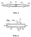
- Fig. 2 is a sectional view of a ferrule used for this purpose, and shows a schematic structure of the ferrule.
- the ferrule has a coated optical fiber guide hole 04, and a fiber insertion hole 05 at the front end.
- the ferrule also includes a cylindrical portion 06 directly related to connection, a holding portion 07 for allowing the ferrule to be stably held in an optical connector, and an inserting portion 08 for allowing an optical fiber to be inserted into the ferrule.
- the ferrule serves as a guide for holding an optical fiber and inserting it into an optical connector when the optical fiber is connected to another optical fiber.
- Very high dimensional accuracy as shown in Table 1 is required in the diameter of the optical fiber insertion hole, the amount of eccentricity of the optical fiber insertion hole, the outer diameter of the ferrule, and the roundness of the outer diameter.
- Dimensional requirements for ferrule Item Dimensional tolerance Outer diameter 2.499 ⁇ 0.0005 mm Amount of eccentricity of optical fiber insertion hole ⁇ 0.7 ⁇ m Size of optical fiber insertion hole 125 + 1 ⁇ m - 0 ⁇ m Roundness of outer diameter ⁇ 0.5 ⁇ m Cylindricity of outer diameter ⁇ 0.5 ⁇ m Surface roughness ⁇ 0.5 ⁇ m
- Yoshizawa et al. prepared a plastic ferrule by transfer molding of a phenolic resin (Research & Development Report, Vol. 32, No. 3, pp. 831-842, 1983).
- a multi-mode fiber with a large core outer diameter of about 50 ⁇ m was mainly used, and such a plastic ferrule was applicable in connecting multi-mode fibers.
- the plastic ferrule cannot be applied to a single-mode fiber with a core outer diameter of 8 to 10 ⁇ m which is in current use for communication.
- the ferrule, prepared by transfer molding requires post-treatment such as flash trimming or heat-treatment after molding.
- plastic ferrule From the viewpoint of economy during a manufacturing process, therefore, the plastic ferrule has not been fully satisfactory.
- plastic materials such as PPS (polyphenylene sulfide) with relatively high thermal resistance and fluidity were considered.
- ferrules were investigated:
- the present invention has been accomplished in the light of the above-described problems.
- the object of the invention is to provide a plastic ferrule for an optical connector to be used in connecting single-mode fibers together. More specifically, its object is to provide a plastic ferrule excellent in the dimensional accuracy of the ferrule outer diameter, mechanical strength, connecting properties, and economy.
- a plastic ferrule for an optical connector which has a fiber guide hole at one end and a fiber insertion hole at the other end and whose outer diameter and eccentricity are controlled, comprising:
- the plastic ferrule for an optical connector may comprise a thermotropic liquid crystalline total aromatic polyester.
- the cylindrical portion may have a taper at an angle of from 30 to 60 degrees, and the length of the insertion hole is 3 mm or more.
- the holding portion or guiding portion may have a mark for showing the relative positional relationship of the ferrule in a mold for injection molding.
- a method for producing a plastic ferrule for an optical connector which is bottomed and cylindrical, has one end opened to define an optical fiber guide hole and has the other end forming an opening for serving as an optical fiber insertion hole, comprising:
- the resin composition may be a resin composition containing at least a thermotropic liquid crystalline total aromatic polyester and an additive for reducing the orientation of the thermotropic liquid crystalline total aromatic polyester.
- the mechanism for controlling the flow of resin may be provided in part of a resin flow channel through which the resin composition is injected into the molds.
- the cylindrical center position of the cavity portion of the mold which forms the ferrule cylindrical portion and which does not move in accordance with the clamping of the molds may be movable relative to the central position of the thin pin forming the optical fiber insertion hole.
- a plastic ferrule for an optical connector whose outer diameter changes and eccentricity have been controlled, the ferrule comprising a resin composition which contains at least a thermotropic liquid crystalline total aromatic polyester and an additive for reducing the orientation of the thermotropic liquid crystalline total aromatic polyester, and which, when injection molded, has anisotropy of the resin of 2 to 5 expressed as the ratio between the values of physical properties measured in the flowing direction of the resin and the direction perpendicular to the flowing direction.
- thermotropic liquid crystalline total aromatic polyester may comprise a polymer of the formula (1) or (2):
- the holding portion or guiding portion may have a mark for showing the relative positional relationship of the ferrule in a mold for injection molding.
- a method for producing a plastic ferrule for an optical connector which comprises a cylindrical portion having one insertion hole for fixing an optical fiber and directly related to connection, a holding portion for allowing the cylindrical portion to be stably held in an optical connector, and an guiding portion for allowing an optical fiber to be guided into the ferrule, comprising:
- the cylindrical center position of the cavity of the mold may be movable relative to the central position of the thin pin forming the optical fiber insertion hole.
- the mechanism for controlling the flow of resin may be provided in part of a resin flow channel through which the resin composition is injected into the molds.
- the object of the invention is attained by a ferrule of a particular shape prepared by the use of a mold having a structure as described below, or a ferrule prepared by using a specific resin composition to be described later on. The following are the details.
- the ferrule of the present invention can achieve a reduction in the amount of eccentricity while retaining a sufficient adhesion, and can fulfill the dimensional conditions for the ferrule shown in Table 1.
- Fig. 3 shows the ferrule of the invention.
- a ferrule 10 of the invention is in a double cylinder shape.
- An end of a first cylinder 11 makes an optical fiber insertion hole 16.
- On the outer periphery of the cylinder 11, a collar-shaped holding portion 12 is disposed for stably holding the cylindrical portion in an optical connector.
- the cylindrical portion 11 ranging from the holding portion 12 to the tip is directly related to the connection of optical fibers.
- a second cylinder 14 projects toward the interior of the cylinder 11 with clearance provided between the cylinder 14 and the cylinder 11.
- the ends of the cylinders 11 and 14 are continuous except the inner diameter area of the cylinder 14.
- the cylinder 14 defines a insertion hole for an optical fiber. That is, an end of a first optical fiber passed through the insertion hole of a first ferrule, and an end of a second optical fiber passed through the insertion hole of a second ferrule contact each other in a connector.
- the contour of the end on the insertion hole side of the cylinder 11 should better be tapered.
- the optical fiber insertion hole is so long compared with conventional examples that an optical fiber can be fixed firmly. If a ferrule is a single cylinder with a thick wall only on the insertion hole side and with a long insertion hole, such a ferrule poses the following problem: When the ferrule after injection molding is cooled, the thick wall portion is slow in cooling, and its sink mark is large compared with the thin wall portion. As a result, the outer diameter of the cylinder differs from that of other parts. In the present invention, on the other hand, the wall thickness of the cylinder 11 is uniform in the longitudinal direction, thus causing no such problem.
- the front end portion of the ferrule is quick in cooling and tends to widen out like a trumpet.
- its cooling rate can be made close to that of other parts by providing the second cylinder.
- that problem can be nearly solved by tapering the front end.
- Such a ferrule can be produced by use of a mold to be described blow.
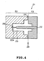
- Fig. 4 shows a conventional typical moid structure
- Fig. 5 shows an example of the structure of a mold used in the present invention.
- a ferrule prepared by using the mold shown in Fig. 5 can attain the object of the invention.
- a mold 21 of Fig. 4 has a structure in which a core pin 22 for forming a coated optical fiber guide hole and an optical fiber insertion hole is provided in a movable-side mold 23, and is held by clamping in a pin receiving portion 26 within a cavity of a fixed-side mold 24.
- the numeral 27 denotes a resin inflow portion
- the numeral 28 denotes a parting line.
- the core pin 22 is set accurately in the center of the cavity, but moves by about 10 to 20 cm when clamped. Between a thin tip 22a of the core pin 22 and the pin receiving portion 26, a clearance measuring at least several ⁇ m is necessary. Thus, when the resin becomes fluid during molding, the core pin vibrates, and eccentricity of several ⁇ m occurs in the resulting ferrule.
- the mold structure of Fig. 5 is intended to fix a core pin 35a to a fixed-side mold 32.
- the mold structure of Fig. 5 is also configured to have a hollow cylindrical space in which the tip of the thin pin 35 is held in a core pin holding hole so as to give a moderate clearance between it and a pin catcher 34, and the thin pin 35 is the axial center of the space.
- a resin which has flowed in through the resin inflow portion (gate) 37 and has moved toward the cylinder tip passes through a first cavity.
- the resin fills a cylindrical space 33 around the thin pin, but does not fill the core pin holding hole 33a in front of the thin pin. Therefore, a ferrule having a through-hole continuously ranging from the coated fiber guide hole to the fiber insertion hole is molded.
- the size of the clearance in front of the thin pin tip is determined by the type of the resin filled. If the clearance is too wide, the resin reaches as far as the area in front of the thin pin, causing a flash, which makes it impossible to form the coated fiber guide hole and the fiber insertion hole continuous with each other.
- the problem of the flash can be solved by controlling the size of the clearance, or by selecting the type of the molding material.
- the suitable length of the fiber insertion hole is 3 mm or more, and the preferred structure of the mold is such that the front end portion of the ferrule is tapered.
- the suitable angle of the taper is from 30 to 60 degrees.
- the mold of Fig. 5 is provided with a cylindrical outer wall 33b of a hollow cylindrical shape having the fiber insertion hole as its central axis.
- the same resin wall thickness can be imparted to those portions of the cylinder corresponding to the tip 06a of the cylindrical portion (corresponding to 11a of Fig. 3) and the middle 06b of the cylindrical portion (corresponding to 11b of Fig. 3) of the ferrule prepared by the conventional mold of Fig. 4.
- Fig. 3 shows the cross sectional structure of the plastic ferrule molded by a mold having the structure of Fig. 5. Since the tip 11a of the cylindrical portion and the middle 11b of the cylindrical portion have the same resin wall thickness, there can be obtained a cylinder contour having uniform outer diameter in the longitudinal direction.
- the use of the mold having the structure of Fig. 5 can give a molded product with minimal eccentricity and few dimensional changes in cylinder outer diameter.
- thermosetting resin such as phenolic resin or epoxy resin
- post-treatment is required.
- an economical ferrule cannot be obtained.
- thermoplastic resin by contrast, has a high viscosity at the time of melting, and so the resin does not enter the clearance between the core thin pin and the pin catcher. Such a resin may be advantageous in terms of the problem of flash.
- Plastic materials that can replace metals or ceramic materials are usually called engineering plastics, and various types have been developed until recently.
- PBT polybutylene terephthalate
- PC polycarbonates
- PA polyamides
- PPO polyphenylene oxides
- POM polyacetals
- High performance engineering plastics include, for example, polyarylates (PAR), polysulfones (PSF), polyphenylene sulfides (PPS), liquid crystal polymers (LCP), polyether sulfones (PES), polyether imides (PEI), polyamideimides (PAI), polyether ether ketones (PEEK) and polyimides (PI).
- PAR polyarylates
- PSF polysulfones
- PPS polyphenylene sulfides
- LCP liquid crystal polymers
- PES polyether sulfones
- PEI polyether imides
- PAI polyamideimides
- PEEK polyether ether ketones
- PI polyimides
- a resin composition be formed from a resin selected from polyether imide resins, polyether sulfone resins and polysulfone resins and an inorganic substance selected from single-crystal inorganic acicular crystals.
- a resin composition By using such a resin composition, excellent effects can be obtained.
- the above-described resins and inorganic substances may be used along or in combination.
- Polyether imides, polyether sulfone, and polysulfones are amorphous high-performance engineering plastics, which are low in the orientation of the resin per se, and high in mechanical strength and heat resistance. Thus, these resins can be used in the present invention preferably.
- polyether imides are polymers of structures expressed by the following formulae (Ia) to (Id) where n is an integer of 10 to 1,000.
- the polymer of the formula (Ia) is commercially available (trade name "Urutem", GE Plastics).
- the polymers of the structures represented by the formulas (Ib) to (Id) are either publicly known, or can be prepared by publicly known methods. However, the polyether imides that can be used in the present invention are not restricted to them.
- polyether sulfones are polymers of structures expressed by the following formulae (IIa) to (IIe) where n is an integer of 10 to 1,000.
- the polymer of the formula (IIa) is commercially available (trade name "Sumika Excel", SUMITOMO CHEMICAL).
- the polymers of the structures represented by the formulas (IIb) to (IIe) are either publicly known, or can be prepared by publicly known methods.
- the polyether sulfones that can be used in the present invention are not restricted to them.
- polysulfones are polymers of structures expressed by the following formulae (IIIa) to (IIIc) where n is an integer of 10 to 1,000.
- the polymer of the formula (IIIa) is commercially available (trade name "Youdel", Teijin Amoco Engineering Plastics).
- the polymers of the structures represented by the formulas (IIIb) to (IIIc) are either publicly known, or can be prepared by publicly known methods. However, the polysulfones that can be used in the present invention are not restricted to them.
- whisker As for additives to be added to the resin, the addition of single-crystal inorganic needle-like crystals and/or fine silica powder among various additives are or is effective in attaining the object of the invention.
- a single crystal inorganic fine powder is called a whisker, and a ceramic series one is the main whisker known. Examples are zinc oxide, magnesium oxide, titanium oxide, aluminum oxide, potassium titanate, aluminum borate, silicon carbide, silicon nitride, graphite, calcium carbonate, zinc carbonate, magnesium hydroxide, and mica. Since whisker is a single crystal needle-like crystal, it gives mechanical strength close to the theoretical value, and it is excellent in heat resistance, wear resistance and chemical resistance.
- whisker is a short fiber with a fiber length generally of several ⁇ m to several hundred ⁇ m, and its aspect ratio is 30 to 300.
- the reason why such a whisker is suitable for the invention may be that basically, it can enhance isotropy.
- the addition of a fibrous material such as glass fiber or carbon fiber makes the anisotropy of resin high, if the resin is based on amorphous resin. Thus, it becomes difficult to achieve the aforementioned dimensional accuracy.
- Excellent whiskers usable in the invention are, for example, potassium titanate, zinc oxide, silicon carbide and mica.
- the zinc oxide whisker, especially a tetrapod-shaped whisker, gave excellent results.
- Silica fine powder also gave excellent results, like the single crystal inorganic needle-like crystal. This additive is also characterized by the absence of anisotropy, small thermal expansion coefficient, and high mechanical strength.
- a polyether imide, polyether sulfone or polysulfone resin composition containing a single crystal inorganic needle-like crystal produced a superb effect.
- the resin composition is a polyether imide, polyether sulfone or polysulfone resin composition containing 20 to 60% by weight of a single crystal inorganic needle-like crystal, an excellent effect is obtained similarly.
- thermoplastic resin is preferred if the problem of flash occurrence is considered.
- thermotropic liquid crystalline total aromatic polyester is preferred.
- the use of such a thermotropic liquid crystalline total aromatic polyester causes no flash, and can achieve roundness and cylindricity which are not more than 1 ⁇ m as shown in Table 1.
- a liquid crystal polymer (LCP) generally shows liquid crystal properties in molten state, and thus its fluidity during molding is very satisfactory.
- the transfer of the resin to the mold is so good that high dimensional accuracy can be achieved.
- the pressure applied to the core pin during molding can be made low, so that a break or bend of the pin can be prevented, even if the fiber insertion hole is 3 mm or more long.
- thermotropic liquid crystalline total aromatic polyester is great in the shear stress dependency of viscosity.
- this polymer is poured into the mold of Fig. 5, and when its flow stops, it solidifies rapidly.
- the arrival of the resin at this clearance is prevented to avoid the problem of flash.
- Liquid crystal polymers of different structures have been synthesized, and the values of their physical properties vary greatly with the chemical structure. As shown in Table 2, liquid crystal polymers can be classified, for convenience's sake, into three types according to the deflection temperature under load (TDUL).
- TDUL deflection temperature under load
- the use of the type I or II polymer having a total aromatic structure is preferred because of its excellency in heat resistance and various types of reliability.
- the total aromatic structure refers to a structure in. which every recurring unit has an aromatic ring, and the same recurring unit does not contain a chain linkage comprising two or more atoms bonded one after another in a chain form. Details of the total aromatic polyester are described in Japanese Patent Application Publication No. 69203/1993.
- an additive which reduces the orientation of the thermotropic liquid crystalline total aromatic polyester.
- the orientation of the liquid crystal polymer is generally high, so that roundness and cylindricity tend to decrease near the tip portion of the ferrule, i.e., the site where the wall thickness becomes nonuniform. Because of this problem, it is preferred to use an additive for reducing the orientation of the resin.
- various inorganic additives are enumerated, such as glass beads, silica beads, graphite, zinc oxide, potassium titanate, zinc oxide, magnesium oxide, titanium oxide, aluminum oxide, potassium titanate, aluminum borate, silicon carbide, silicon nitride, graphite, calcium carbonate, zinc carbonate, and magnesium hydroxide.
- fibrous additives such as glass fiber and carbon fiber are not used.
- the amount of the additive added is determined in a range in which the fluidity of the resin is not decreased. This amount can be selected suitably within the range of from 20% to 70%, preferably from 30% to 60%.
- the term "roundness" refers to deviation from the center of a reference circle which is a circle with a diameter of 2.5 mm.
- the present invention also focuses on "anisotropy" of the resin composition, and has found that when the orientation of the resin is in a suitable range, a very good plastic ferrule can be obtained.
- the "anisotropy" of the resin composition it is appropriate to use the ratio between the values of the physical properties of the resin in the flowing direction and the direction perpendicular to the flowing direction when the resin composition is injection molded.
- the resin composition having this ratio of 5 or less is used (however, the "ratio" referred to herein is that obtained by dividing the larger value by the smaller value).
- an ASTM test sample for use in the evaluation of a resin's physical properties, or a flat plate (e.g., 60 x 60 x 3 mm).
- a mold structure having a gate in an end face is suitable.
- a test piece of a suitable shape is cut out of the molded product by cutting it in the flowing direction of the resin and in the direction perpendicular to the flowing direction.
- the physical properties of the test piece are evaluated, whereby the anisotropy of the resin composition can be found. The higher the ratio, the more the resin is oriented in the flowing direction.
- the physical properties may be linear expansion coefficient, mold shrinkage coefficient, and flexural modulus, of which linear expansion coefficient can be used most preferably.
- the linear expansion coefficient in the flowing direction is normally larger than that in the direction perpendicular to it.
- the anisotropy of from 2 to 5 has been found to give excellent results. If the anisotropy is more than 5, the roundness is 1 ⁇ m or more, thereby decreasing the molding accuracy. This may be because when the anisotropy of the resin is great, the flow of the resin or the shrinkage at cooling is nonuniform, leading to a decrease in the molding accuracy. Generally, when the anisotropy of resin is high, the linear expansion coefficient in the flowing direction lowers.
- the linear expansion coefficient of the resin be so low as to become close to the linear expansion coefficient of a silica optical fiber. If the anisotropy of the resin is less than 2, on the other hand, the linear expansion coefficient goes beyond 1.5 x 10 -5 , the limiting value required in temperature and humidity cycling test to be described later on.
- a ferrule of any structure can attain the object of the present invention.
- a resin composition containing a thermotropic liquid crystalline total aromatic polyester and an additive for reducing the orientation of the thermotropic liquid crystalline total aromatic polyester, and having the anisotropy of the resin of 2 to 5 is injected into a mold of a structure as illustrated in Fig. 6 or 7 to form a ferrule.
- Fig. 6A is a sectional view showing the whole of this mold 41, while Fig. 6B shows the essential part of the mold.
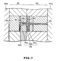
- Fig. 7 shows the mold of Fig. 6 adapted to form a taper, as a view in which the mold is attached to mounting plates 40a, 40b.
- a core pin 44 is fixed to a fixed-side mold 42.
- the core pin 44 has a thin pin 45 for forming an optical fiber insertion hole.
- a pin catcher 46 for forming a coated optical fiber guide hole is fixed to a movable-side mold 43, and accepts the thin pin 45 during clamping of the molds. That is, a columnar groove 46a is present in the front end portion of the pin catcher, and the thin pin 45 is held there out of contact with its inside.
- the numeral 47 denotes a resin inflow portion, 48 a parting line, and 40c a gauge for eccentricity adjustment.
- a cavity 49 is defined between the movable-side mold 43 and the fixed-side mold 42.
- Molten resin is injected into the molds through the resin inflow portion 47.
- the resin introduced into a first cavity 49a forms a cylindrical portion of a ferrule
- the resin introduced into a second cavity 49b forms a holding portion
- the resin introduced into a third cavity 49c forms an guiding portion.
- a ferrule was formed using the mold of Fig. 6, and measured for the roundness and the linear expansion coefficient in the flowing direction. The results are depicted in Figs. 8 and 9.
- Fig. 8 shows the roundness at a site 4 mm apart from the tip of the ferrule.
- the anisotropy exceeds 5
- the roundness is 1 ⁇ m or more, resulting in decreased molding accuracy.
- a plastic ferrule has a slightly wide margin in comparison with zirconia. If the roundness of 1 ⁇ m or less can be achieved, therefore, the required connecting characteristics are obtained.
- Fig. 9 shows the relationship between the anisotropy and the linear expansion coefficient in the flowing direction of a resin composition.
- the anisotropy of the resin is less than 2, the value of the linear expansion coefficient in the flowing direction exceeds 1.5 x 10 -5 , the value required of reliability in temperature and humidity cycling test.
- the amount of the additive added to decrease the orientation of the thermotropic liquid crystalline total aromatic polyester added varies with the type of the additive.
- a resin composition containing the additive so as to give anisotropy of 2 to 5 is used.
- Japanese Patent Application Publication No. 69203/1993 discloses an example of adding various additives to the thermotropic liquid crystalline total aromatic polyester. These additives, however, include some additives which increase the anisotropy of the resin composition. They are not based on our idea of imparting anisotropy of 2 to 5 as in the present invention. Thus, the roundness is 2 ⁇ m or more in Japanese Patent Application Publication No. 69203/1993.
- the resin composition of the present invention may, if desired, contain additives such as surface treating agents, colorants, or mold release agents. For the mold used in the invention, in particular, the addition of a mold release agent is effective.
- a mold of the structure shown in Fig. 5 can suppress fluctuations in eccentricity during molding.
- the absolute value of eccentricity does not necessarily become zero. That is, even if the manufacturing accuracy of mold parts is maximized and their eccentricity is set at zero on the parts level, clearance of at least 1 to 2 ⁇ m is necessary to combine mold parts.
- the amount of eccentricity that can be expected is not necessarily level zero, but some eccentricity arises.
- the provision of a mechanism for controlling the amount of eccentricity is necessary for making the present invention more effective. This invention uses the following two mechanisms for adjusting the amount of eccentricity, thereby reducing it.
- a zirconia ferrule requires eccentricity of less than 0.7 ⁇ m.
- the same characteristics can be achieved with eccentricity of not more than 1 ⁇ m. This is because a highly rigid material such as zirconia undergoes no deformation of a ferrule itself, while a plastic material can be expected to exhibit certain elastic deformation, thus somewhat broadening the tolerance for the amount of eccentricity.
- a mark for indicating the position of a molded ferrule in a mold is preferably provided in part of a holding portion or guiding portion of the ferrule.
- Fig. 12 presents the results of measurement of the eccentric position of a ferrule of the structure of Fig. 6 which was molded from a resin composition containing a thermotropic liquid crystalline total aromatic polyester and an additive for reducing the orientation of the thermotropic liquid crystalline total aromatic polyester, and having anisotropy of 2 to 5.
- Eccentricity of 3.7 ⁇ m on the average occurs, but variations in eccentricity are very small, and the deviation is 0.2 ⁇ m. The same holds true when control of eccentricity is performed.
- optical PC(Physical Conatact) connection is carried out using the ferrule of the present invention, for example, there is a case in which two ferrules are opposed to each other in the same positional relationship with their positions in the mold as a reference. In this case, the relative positional relationship of optical fibers becomes the closest, decreasing the connection loss. After the ferrule is pushed out of the mold and the sprue and runner are treated, nothing indicates the position of the ferrule in the mold. Thus, if the aforementioned mark is provided in part of the ferrule other than the cylindrical portion, its position is referred to so that the ferrules can be opposed to each other.
- This "aligning procedure" can be realized only by the plastic ferrule of the present invention provided with a registration mark.
- the eccentricity of each ferrule mounted with a fiber is measured individually, the ferrule is marked based on the results, and alignment is performed with reference to the marked position.
- the use of a ferrule with a marking as in the invention requires no such a conventional procedure, and thus enables an optical connector to be provided at a low cost.
- a structure with a spigot joint portion is available, or a taper pin or a cotter block may be provided. Either method can be selected where necessary.
- the type of a gate for introducing a resin into a mold is a pin point gate, a ring gate or a film gate, and any of them can be selected according to the gate position.
- a fast injection molding technique injection pressure is decreased
- a slow injection molding technique involving as low an injection speed as possible for decreasing distortion after molding can be utilized according to the need.
- the molding machine usable is a small injection molding machine with a relatively low mold clamping pressure (50 t or less).
- a publicly known hydraulic injection molding machine an electrically actuated injection molding machine with a servomotor as a drive source, or a hybrid type device having a hydraulic system/electric feed system on the injection side/clamping side.
- Utmost care should be taken in the molding machine for the parallelism between a moving plate moving with the mold attached and a fixed plate. Poor parallelism results in decreased registration accuracy of the molds, which is unsuitable for precision molding.
- Parallelism is defined as an error in the distance between both plates, and its value should be at least within 50 ⁇ m, preferably within 30 ⁇ m.
- the plastic ferrule of the present invention can be utilized for products related to an SC connector. It is applicable to an adapter for a double ended plug cord and a junction in an optical module. Basically, this ferrule can be applied to all optical connectors (FC connector, ST connector) with a ferrule outer diameter of 2.5 mm.
- optical interconnection is expected to find use in various information processors, and numerous optical connectors and ferrule parts will become necessary.
- a plastic ferrule was molded using a mold for injection molding shown in Figs. 13 and 14.
- the length of a fiber insertion hole was set at 3.5 mm, and the taper angle of the tip portion was set at 40 degrees.
- a mold described in detail in Figs. 13 and 14 is the same as the mold of the present invention illustrated in Fig. 5. Thus, the same parts as in Fig. 5 were assigned the same numerals.
- a cavity 36 was formed between a movable-side mold 31 and a fixed-side mold 32, and a thin pin 35 of a fixed core pin 35a was fitted into one end of a through-hole of a pin catcher 34 so as to be supported at both ends thereof. From this state, a shift to an injection step was made, and molten resin was injected through a gate 37 into the cavity 36.
- the resin was divided and moved to the right and the left.
- Molten resin charged into a second cavity 36b formed a holding portion of a ferrule
- molten resin charged into a third cavity 36c formed an guiding portion of the ferrule
- molten resin charged into a first cavity 36a formed a cylindrical portion of the ferrule.
- a fiber insertion hole and a coated fiber guide hole were formed.
- the movable-side mold 31 and the fixed-side mold 32 were fixed to a clamping platen of an injection molding machine (not shown) via a movable-side mounting plate 70 and a fixed-side mounting plate 60.
- the molding materials used were as follows: Total aromatic thermotropic liquid crystal polyester (type II) 50 parts by weight Glass beads (average particle size 30 ⁇ m) 50 parts by weight
- injection molding conditions are shown in Table 3.
- Item Conditions Resin drying 150°C, 5 hours Cylinder temperature Rear portion 280°C Intermediate portion 280°C Nozzle portion 300°C Mold temperature 70°C Injection pressure 800 kg/cm 2 Screw back pressure 80 kg/cm 2 Holding pressure 1200 kg/cm 2 Injection speed 5.7 cm/sec Screw speed 300 rpm Iniection time 0.22 second Metering time 1.20 seconds
- Fig. 15 shows the outer diameter of a plastic ferrule, prepared under the above-mentioned conditions, in the longitudinal direction ranging from the tip of the cylindrical portion to the holding portion.
- Fig. 16 shows the outer diameter of a plastic ferrule, prepared with the use of the resin other than total aromatic thermotropic liquid crystal polyester by a conventional method, in the longitudinal direction ranging from the tip of the cylindrical portion to the holding portion.
- the outer diameter of the conventional ferrule is not uniform, and varies widely particularly in the portions of the cylinder with a large resin wall thickness.
- variations in the outer diametral shape are very small in the portions ranging from the tip of the cylindrical portion to the holding portion.
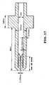
- Fig. 17 is a sectional view of the plastic ferrule prepared under those conditions.
- Optical connectors were assembled using the plastic ferrules molded using the mold of Fig. 6 and the plastic ferrules molded using the mold of Fig. 3, and measured for the connection loss. These molding materials used were the same as the above total aromatic thermotropic liquid crystal polyester and so on.
- the plastic ferrule molded using the mold of Fig. 6 and the plastic ferrule molded using the mold of Fig. 3 each had eccentricity of 0.5 ⁇ m. Grinding was AdPC grinding.
- the value of connection loss anticipated theoretically from the eccentricity of 0.5 ⁇ m is about 0.05 dB.
- the connection loss of the optical connector using the ferrule molded using the mold of Fig. 6 was 0.2 dB, a value greater than the theoretically expected value.
- a plastic ferrule has eccentricity of 0.5 ⁇ m or less can not be prepared by a conventional method.
- connection loss of the optical connector using the ferrule molded using the mold of Fig. 3 was 0.13 dB. This value was higher than the value theoretically expected from eccentricity, but was smaller than that of the ferrule molded using the mold of Fig. 6. As noted from this, connection loss characteristics are improved by decreasing variations in the outer diameter of the ferrule. The connection loss of 0.5 dB or less is not problematical for practical use.
- a ferrule with eccentricity of 1.0 ⁇ m or less can be obtained in 80 % yield when a ferrule is molded by using the mold of Fig. 3, but in 30 % yield when a ferrule is molded by using the mold of Fig. 3.
- the ferrule of the invention gave a connection loss of 0.25 dB even when it had eccentricity of 1 ⁇ m. This ferrule was fully feasible.
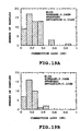
- Fig. 18A and 18B show connection loss caused when a commercially available ferrule (zirconia or the like) and a plastic ferrule were connected together by a commercially available zirconia split alignment sleeve.
- Fig. 18A shows connection loss obtained when the plastic ferrule was a ferrule molded using the mold of Fig. 6.
- Fig. 18B shows connection loss for the ferrule of Fig. 3.
- Figs. 19A and 19B show connection loss for random connection of two plastic ferrules connected by a commercially available zirconia split alignment sleeve.
- Fig. 19A shows connection loss for the ferrule molded by the mold of Fig. 6.
- Fig. 19B shows connection loss for the ferrule of Fig. 3.
- these connectors all exhibited connection loss of 0.5 dB or less. They had the excellent effect of the present invention, and were producible in high yields.
- Fig. 20 shows the return loss for the ferrule molded using the mold of Fig. 3.
- Fig. 21 shows the results of temperature and humidity cycling test of the plastic ferrule according to the present invention.
- This ferrule involved few changes in characteristics, such as connection loss and return loss, associated with changes in temperature and humidity. Thus, the ferrule was found to have excellent weather resistance.
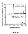
- Fig. 22 shows the results of mating test in which a ferrule was attached to and detached from a zirconia split alignment sleeve or a plastic split alignment sleeve 500 times.
- the connection loss sometimes worsened.
- a cleaning procedure returned the connection loss to the original value.
- mechanical deterioration may have not occurred.
- connection loss did not worsen without cleaning.
- the zirconia split sleeve and the plastic split sleeve were both free from deterioration of the connecting characteristics after 500 matings, and showed satisfactory mating characteristics.
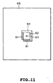
- a plastic ferrule was molded using the mold for injection molding illustrated in Figs. 6A and 6B. The resulting ferrule is shown in Fig. 23.
- the length L of a fiber insertion hole 102 of a ferrule 101 was set at 3.5 mm, and the taper angle of a taper portion 103 of the tip was set at 40 degrees.
- the ferrule 101 comprised a holding portion 106 for making the ferrule stable held in an optical connector, and an guiding portion 107 for the guide of an optical fiber into the ferrule.
- a mark 108 was provided on the end face of the fiber guiding portion of the ferrule 101.
- An example of the mark 108 is a depression provided on the periphery of the end face of the fiber guiding portion.
- Various other marks may be used which are easy to see and can be formed by a simple method.
- the molding materials used were as follows: Total aromatic thermotropic liquid Crystal polyester (type II) 50 parts by weight Silica powder (average particle size 10 ⁇ m) 50 parts by weight
- the linear expansion coefficient in the flowing direction was 0.92 x 10 -5
- the linear expansion coefficient in the perpendicular direction was 4.5 x 10 -5
- the anisotropy of the resin was 4.9.
- the linear expansion coefficient was measured in the range of from 30°C to 150°C.
- the injection molding conditions are the same as shown in Table 3 of Example 1.
- the wall thickness of the ferrule differs at sites near the tip, thereby producing a concave "necking" in the vicinity of the ferrule tip.
- this necking is located 1 to 3 mm apart from the tip, and it is not simply that a necking appears inside and a convex shape develops outside.
- the difference in outer diameter between the tip and the junction 3 mm or more apart from the tip is 1 ⁇ m or less. This small difference does not exert a marked adverse effect on the connecting characteristics.
- removal of the values in the portions from the tip to the site 1-3 mm apart is substantially effective.
- the value of cylindricity was more than 0.5 ⁇ m. For the same reasons as stated previously, however, if it is less than 1.5 ⁇ m, a substantially unproblematic ferrule is obtained.
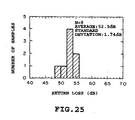
- Figs. 24A and 24B The results of the connection loss characteristics are shown in Figs. 24A and 24B.
- Fig. 24A gives the connecting characteristics for connection between a zirconia master connector (eccentricity: 0.3 ⁇ m or less) and a plastic ferrule
- Fig. 24B gives the connecting characteristics for connection between plastic ferrules. With the sc connector, the value of 0.5 dB or less is required for connection with the master connector.
- Plastic ferrules were prepared in the same manner as in Example 2, except that each of the resin compositions shown in Table 6 was used as the resin composition. The resulting ferrules achieved excellent characteristics as in Example 2.
- Resin composition used in Examples 3 to 8 Ex. Liquid crystal polymer Additive Linear expansion coefficient Flowing direction Perpendicular direction Anisotropy 3
- Type II Potassium titanate 50% 0.94x10 -5 4.6x10 -5 4.9 4
- Type II Zinc oxide 40% 1.3x10 -5 5.6x10 -5 4.3 5
- Type I Glass beads 40% 0.87x10 -5 3.7x10 -5 4.3 7
- Type I Potassium titanate 50% 0.90x10 -5 2.9x10 -5 3.2
- a ferrule was prepared in the same manner as in Example 2, except that a liquid crystal polymer (anisotropy: 9) containing 30% glass fiber was used as the resin composition. Its dimensional accuracy was evaluated, finding that the roundness and cylindricity were 2 ⁇ m and 8 ⁇ m, respectively, i.e., unsatisfactory characteristics. The amount of eccentricity was not less than 3 ⁇ m, even when each of the aforementioned eccentricity adjusting mechanisms was used.
- a plastic ferrule was prepared in the same manner as in Example 2, except that a type III liquid crystal polymer was used.
- the dimensional characteristics achieved were practically the same as in Example 2.
- temperature and humidity cycling test showed that the return loss decreased from 45 dB to 30 dB after 10 cycles.
- Plastic ferrules were prepared in the same manner as in Example 2, except that each of the resin compositions shown in Table 7 was used as the resin composition. The problems listed in Table 7 occurred, and the resulting plastic ferrules did not exhibit excellent characteristics. Results of Comparative Examples 3 to 12 Comp Ex. Liquid crystal polymer Additive Anisotropy Problem 3 Type II Glass beads 40% 6.2 Roundness: 1.5 ⁇ m Cylindricity: 3.5 ⁇ m . 4 Type II Glass beads 60% 1.7 Temp/humid.
- the present invention is advantageous in that it provides a plastic ferrule for an optical connector which can be used in connecting single mode fibers and which is excellent in connecting characteristics, reliability and economy.
- the single mode ferrule now on the marked requires that a flange for holding the ferrule in an adapter be attached to the ferrule after production.
- the plastic ferrule of the present invention on the other hand, has a holding portion integrally molded, and thus can omit the step of mounting the flange. Furthermore, the use of a plastic material enables the invention to cut down on the materials cost.
- the invention is highly versatile and can be applied to various optical connectors.
Landscapes
- Physics & Mathematics (AREA)
- Engineering & Computer Science (AREA)
- Manufacturing & Machinery (AREA)
- Mechanical Engineering (AREA)
- General Physics & Mathematics (AREA)
- Optics & Photonics (AREA)
- Mechanical Coupling Of Light Guides (AREA)
- Moulds For Moulding Plastics Or The Like (AREA)
- Injection Moulding Of Plastics Or The Like (AREA)
- Compositions Of Macromolecular Compounds (AREA)
Priority Applications (2)
| Application Number | Priority Date | Filing Date | Title |
|---|---|---|---|
| EP01202276A EP1146370B1 (fr) | 1997-02-21 | 1998-02-19 | Procédé de fabrication d'un embout plastique pour un connecteur optique |
| EP01202310A EP1130435A1 (fr) | 1997-02-21 | 1998-02-19 | Embout plastique pour un connecteur optique |
Applications Claiming Priority (6)
| Application Number | Priority Date | Filing Date | Title |
|---|---|---|---|
| JP37322/97 | 1997-02-21 | ||
| JP3732297 | 1997-02-21 | ||
| JP3732297 | 1997-02-21 | ||
| JP1622998 | 1998-01-28 | ||
| JP16229/98 | 1998-01-28 | ||
| JP01622998A JP3642380B2 (ja) | 1998-01-28 | 1998-01-28 | 光コネクタ用プラスチックフェルール |
Related Child Applications (2)
| Application Number | Title | Priority Date | Filing Date |
|---|---|---|---|
| EP01202276A Division EP1146370B1 (fr) | 1997-02-21 | 1998-02-19 | Procédé de fabrication d'un embout plastique pour un connecteur optique |
| EP01202310A Division EP1130435A1 (fr) | 1997-02-21 | 1998-02-19 | Embout plastique pour un connecteur optique |
Publications (2)
| Publication Number | Publication Date |
|---|---|
| EP0860723A2 true EP0860723A2 (fr) | 1998-08-26 |
| EP0860723A3 EP0860723A3 (fr) | 1999-08-04 |
Family
ID=26352510
Family Applications (3)
| Application Number | Title | Priority Date | Filing Date |
|---|---|---|---|
| EP01202310A Withdrawn EP1130435A1 (fr) | 1997-02-21 | 1998-02-19 | Embout plastique pour un connecteur optique |
| EP98301203A Ceased EP0860723A3 (fr) | 1997-02-21 | 1998-02-19 | Embout plastique pour un connecteur optique et son procédé de fabrication |
| EP01202276A Expired - Lifetime EP1146370B1 (fr) | 1997-02-21 | 1998-02-19 | Procédé de fabrication d'un embout plastique pour un connecteur optique |
Family Applications Before (1)
| Application Number | Title | Priority Date | Filing Date |
|---|---|---|---|
| EP01202310A Withdrawn EP1130435A1 (fr) | 1997-02-21 | 1998-02-19 | Embout plastique pour un connecteur optique |
Family Applications After (1)
| Application Number | Title | Priority Date | Filing Date |
|---|---|---|---|
| EP01202276A Expired - Lifetime EP1146370B1 (fr) | 1997-02-21 | 1998-02-19 | Procédé de fabrication d'un embout plastique pour un connecteur optique |
Country Status (3)
| Country | Link |
|---|---|
| US (1) | US5975770A (fr) |
| EP (3) | EP1130435A1 (fr) |
| DE (1) | DE69827531T2 (fr) |
Cited By (2)
| Publication number | Priority date | Publication date | Assignee | Title |
|---|---|---|---|---|
| WO2002069009A1 (fr) * | 2001-02-26 | 2002-09-06 | Chikuma Industrial Limited | Ferrule pour connecteur de fibre optique et procede de production |
| EP1450188A3 (fr) * | 2003-02-21 | 2005-02-09 | Itt Manufacturing Enterprises, Inc. | Dispositif pour indexer l'extrémité d'une fibre optique |
Families Citing this family (14)
| Publication number | Priority date | Publication date | Assignee | Title |
|---|---|---|---|---|
| JP4361193B2 (ja) * | 1999-04-23 | 2009-11-11 | 株式会社フジクラ | 光フェルール及びこの光フェルールを用いた光コネクタ |
| JP2001215358A (ja) * | 2000-01-31 | 2001-08-10 | Molex Inc | 光ファイバ用フェルール及びその製造方法 |
| JP2002174749A (ja) * | 2000-09-27 | 2002-06-21 | Kyoei Senzai Kk | 光ファイバ接続用コネクタの複合フェルール及びこのフェルールの製造方法並びにこのフェルールを用いた光ファイバ接続用コネクタ |
| JP2003014988A (ja) * | 2001-06-28 | 2003-01-15 | Ykk Corp | 光コネクタ及びそれに用いる光コネクタ用フェルール |
| US6744944B2 (en) * | 2001-10-05 | 2004-06-01 | The Furukawa Electric Co., Ltd. | Optical coupling module having a first and second ferrules |
| JP2003248136A (ja) * | 2002-02-25 | 2003-09-05 | Kyoei Senzai Kk | 光ファイバ用複合フェルール及び光ファイバ接続用コネクタ |
| US20040224145A1 (en) * | 2003-05-05 | 2004-11-11 | Weir John Douglas | Self-decontaminating or self-cleaning coating for protection against hazardous bio-pathogens and toxic chemical agents |
| US20060115217A1 (en) * | 2004-11-29 | 2006-06-01 | Us Conec, Ltd. | Multi-fiber ferrule and a mold therefor |
| US8337095B2 (en) | 2009-09-30 | 2012-12-25 | Corning Cable Systems Llc | Tapered-channel ferrules and optical fiber connectors employing same |
| TW201136077A (en) * | 2010-04-01 | 2011-10-16 | Hon Hai Prec Ind Co Ltd | Device and method for manufacturing optical couple connetor |
| JP6464007B2 (ja) * | 2015-03-25 | 2019-02-06 | 株式会社フジクラ | 光コネクタフェルール |
| WO2018152175A1 (fr) * | 2017-02-15 | 2018-08-23 | Molex, Llc | Ensembles optiques multifibres et leur procédé de fabrication |
| JP7388368B2 (ja) | 2019-02-04 | 2023-11-29 | 住友電気工業株式会社 | フェルール及び光コネクタ |
| JP7559766B2 (ja) | 2019-11-14 | 2024-10-02 | 住友電気工業株式会社 | 光ファイバ接続部品及び光ファイバ接続構造 |
Family Cites Families (21)
| Publication number | Priority date | Publication date | Assignee | Title |
|---|---|---|---|---|
| JPS5781224A (en) * | 1980-11-11 | 1982-05-21 | Hitachi Ltd | Production of plastic optical connector |
| JPS5938707A (ja) * | 1982-08-30 | 1984-03-02 | Fujitsu Ltd | 光フアイバコネクタ |
| JPS59109010A (ja) * | 1982-12-14 | 1984-06-23 | Keru Kk | 光コネクタのフエル−ル鋳造用金型およびその製造方法 |
| JPS60196706A (ja) * | 1984-03-21 | 1985-10-05 | Nippon Telegr & Teleph Corp <Ntt> | 光フアイバの接続方法 |
| JPS60224516A (ja) * | 1984-04-23 | 1985-11-08 | Hitachi Chem Co Ltd | 光フアイバコネクタ用フエル−ルの成形金型 |
| JPS617814A (ja) * | 1984-06-21 | 1986-01-14 | Sumitomo Electric Ind Ltd | 光コネクタフエル−ル |
| CA1284903C (fr) * | 1984-07-18 | 1991-06-18 | Anne Holt | Composants pour le raccordement reciproque ou le branchement de fibres optiques |
| JPS61144314A (ja) * | 1984-12-19 | 1986-07-02 | Keru Kk | 成形金型 |
| JPS61285282A (ja) * | 1985-06-12 | 1986-12-16 | Polyplastics Co | 光伝送路接続端子組成物 |
| JPH01243005A (ja) * | 1988-03-24 | 1989-09-27 | Nec Corp | 光ファイバコネクタのフェルール |
| JP2825269B2 (ja) * | 1989-05-02 | 1998-11-18 | ケル株式会社 | 光コネクタ用フェルールおよびその製造方法 |
| US5193133A (en) * | 1992-01-21 | 1993-03-09 | Methode Electronics, Inc. | Method of terminating optical fiber utilizing a plastic alignment ferrule with polishing pedestal |
| FR2689253B1 (fr) * | 1992-03-24 | 1997-01-24 | Souriau & Cie | Dispositif de moulage comportant une contre-piece de guidage de broches pour le moulage de viroles de connecteurs de fibres optiques, et virole moulee au moyen d'un tel dispositif. |
| US5333223A (en) * | 1993-04-13 | 1994-07-26 | Methode Electronics, Inc. | Plastic fiber alignment ferrule with polishing pedestal |
| WO1995025770A1 (fr) * | 1994-03-18 | 1995-09-28 | Mitsubishi Denki Kabushiki Kaisha | Composition resineuse destinee au moulage de pieces detachees de precision, manchon et virole fabriques a partir de cette composition |
| US5602951A (en) * | 1994-04-14 | 1997-02-11 | Sumitomo Electric Industries, Ltd. | Ferrule for optical connector and process for making same |
| JPH0815568A (ja) * | 1994-07-04 | 1996-01-19 | Nippon Telegr & Teleph Corp <Ntt> | 光コネクタ用プラスチックフェルールおよびその製造方法 |
| JP3286724B2 (ja) * | 1994-08-23 | 2002-05-27 | ポリプラスチックス株式会社 | 射出成形品 |
| US5621836A (en) * | 1994-11-28 | 1997-04-15 | Methode Electronics, Inc. | Plastic fiber alignment ferrule and termination method |
| JP3593779B2 (ja) * | 1995-03-01 | 2004-11-24 | 東レ株式会社 | 光ファイバー接続端子用成形品 |
| JP3096637B2 (ja) * | 1996-07-17 | 2000-10-10 | 本田技研工業株式会社 | コンデンサ |
-
1998
- 1998-02-19 EP EP01202310A patent/EP1130435A1/fr not_active Withdrawn
- 1998-02-19 EP EP98301203A patent/EP0860723A3/fr not_active Ceased
- 1998-02-19 EP EP01202276A patent/EP1146370B1/fr not_active Expired - Lifetime
- 1998-02-19 DE DE69827531T patent/DE69827531T2/de not_active Expired - Lifetime
- 1998-02-20 US US09/027,472 patent/US5975770A/en not_active Expired - Lifetime
Cited By (2)
| Publication number | Priority date | Publication date | Assignee | Title |
|---|---|---|---|---|
| WO2002069009A1 (fr) * | 2001-02-26 | 2002-09-06 | Chikuma Industrial Limited | Ferrule pour connecteur de fibre optique et procede de production |
| EP1450188A3 (fr) * | 2003-02-21 | 2005-02-09 | Itt Manufacturing Enterprises, Inc. | Dispositif pour indexer l'extrémité d'une fibre optique |
Also Published As
| Publication number | Publication date |
|---|---|
| DE69827531D1 (de) | 2004-12-16 |
| EP1146370A3 (fr) | 2001-10-24 |
| DE69827531T2 (de) | 2005-10-27 |
| US5975770A (en) | 1999-11-02 |
| EP1130435A1 (fr) | 2001-09-05 |
| EP1146370A2 (fr) | 2001-10-17 |
| EP0860723A3 (fr) | 1999-08-04 |
| EP1146370B1 (fr) | 2004-11-10 |
Similar Documents
| Publication | Publication Date | Title |
|---|---|---|
| US5975770A (en) | Plastic ferrule for optical connector and method for production thereof | |
| US6142677A (en) | Plastic split optical alignment sleeve for optical connectors and method of fabricating the same | |
| EP1089100B1 (fr) | Un embout ayant une fibre optique incorporée faisant partie intégrale de celui-ci et son procédé de fabrication | |
| JP3803072B2 (ja) | 多芯フェルール及び多芯フェルールの製造方法 | |
| CN1186252A (zh) | 光学纤维接头用的箍及其制造方法 | |
| KR960705232A (ko) | 광 화이버 커넥터용 캐피럴리와 그 제조방법(Capillary for optical fiber connectors and method of manufacturing the same) | |
| US6144505A (en) | Optical component, method of molding optical component, and mold for optical component | |
| CN1307450C (zh) | 光纤定位部件 | |
| JP3314805B2 (ja) | 光コネクタ用プラスチック割りスリーブおよびその製造方法 | |
| JP3540216B2 (ja) | フェルールとその成形方法 | |
| JP2004038005A (ja) | フェルール及びフェルールの製造方法 | |
| JP3642380B2 (ja) | 光コネクタ用プラスチックフェルール | |
| JPH06299072A (ja) | 光ファイバ用コネクタフェルール | |
| US6347890B2 (en) | Optical ferrule | |
| JPH10293232A (ja) | 光コネクタ用プラスチックフェルールおよびその製造方法 | |
| JPH06238711A (ja) | プラスチックの射出成形方法および装置 | |
| JP3274224B2 (ja) | プラスチック光学素子の成形金型およびそのプラスチック光学素子 | |
| JPH1031134A (ja) | 光コネクタ用プラスチック精密スリーブおよびその金型 | |
| JP3346753B2 (ja) | 射出成形金型 | |
| JP4350360B2 (ja) | 多芯フェルール及び多芯フェルールの製造装置 | |
| JP3282106B2 (ja) | 光コネクタ用プラスチック割りスリーブおよびその製造方法 | |
| JP3287390B2 (ja) | 光コネクタ用フェルール射出成形用金型 | |
| JP2886741B2 (ja) | レンズホルダ及びその製造方法 | |
| JP2001147343A (ja) | 光コネクタ用フェルール | |
| JP2000121872A (ja) | 光コネクタ用プラスチックフェルール及びその製造方法 |
Legal Events
| Date | Code | Title | Description |
|---|---|---|---|
| PUAI | Public reference made under article 153(3) epc to a published international application that has entered the european phase |
Free format text: ORIGINAL CODE: 0009012 |
|
| 17P | Request for examination filed |
Effective date: 19980219 |
|
| AK | Designated contracting states |
Kind code of ref document: A2 Designated state(s): DE FR GB |
|
| AX | Request for extension of the european patent |
Free format text: AL;LT;LV;MK;RO;SI |
|
| PUAL | Search report despatched |
Free format text: ORIGINAL CODE: 0009013 |
|
| RIC1 | Information provided on ipc code assigned before grant |
Free format text: 6G 02B 6/38 A, 6B 29C 45/26 B, 6B 29C 45/36 B |
|
| AK | Designated contracting states |
Kind code of ref document: A3 Designated state(s): AT BE CH DE DK ES FI FR GB GR IE IT LI LU MC NL PT SE |
|
| AX | Request for extension of the european patent |
Free format text: AL;LT;LV;MK;RO;SI |
|
| AKX | Designation fees paid |
Free format text: DE FR GB |
|
| 17Q | First examination report despatched |
Effective date: 20001010 |
|
| STAA | Information on the status of an ep patent application or granted ep patent |
Free format text: STATUS: THE APPLICATION HAS BEEN REFUSED |
|
| 18R | Application refused |
Effective date: 20040910 |