EP0860808A2 - Matrixanzeigevorrichtung mit einer zusätzlichen Ikonenzeile - Google Patents
Matrixanzeigevorrichtung mit einer zusätzlichen Ikonenzeile Download PDFInfo
- Publication number
- EP0860808A2 EP0860808A2 EP98300716A EP98300716A EP0860808A2 EP 0860808 A2 EP0860808 A2 EP 0860808A2 EP 98300716 A EP98300716 A EP 98300716A EP 98300716 A EP98300716 A EP 98300716A EP 0860808 A2 EP0860808 A2 EP 0860808A2
- Authority
- EP
- European Patent Office
- Prior art keywords
- display
- icon
- area
- dots
- primary
- Prior art date
- Legal status (The legal status is an assumption and is not a legal conclusion. Google has not performed a legal analysis and makes no representation as to the accuracy of the status listed.)
- Withdrawn
Links
- 239000011159 matrix material Substances 0.000 title claims abstract description 25
- 230000003287 optical effect Effects 0.000 claims description 8
- 230000010287 polarization Effects 0.000 claims description 8
- 239000013078 crystal Substances 0.000 claims description 4
- 239000004020 conductor Substances 0.000 claims description 3
- 239000004973 liquid crystal related substance Substances 0.000 claims description 3
- 239000000758 substrate Substances 0.000 claims description 3
- 230000001788 irregular Effects 0.000 abstract description 3
- 239000011521 glass Substances 0.000 description 4
- 239000000463 material Substances 0.000 description 3
- 230000005855 radiation Effects 0.000 description 3
- 230000008859 change Effects 0.000 description 2
- 230000000694 effects Effects 0.000 description 2
- 102000003668 Destrin Human genes 0.000 description 1
- 108090000082 Destrin Proteins 0.000 description 1
- 102100029108 Elongation factor 1-alpha 2 Human genes 0.000 description 1
- 102100039939 Growth/differentiation factor 8 Human genes 0.000 description 1
- 108050006583 Growth/differentiation factor 8 Proteins 0.000 description 1
- 101000841231 Homo sapiens Elongation factor 1-alpha 2 Proteins 0.000 description 1
- 238000010521 absorption reaction Methods 0.000 description 1
- 230000005540 biological transmission Effects 0.000 description 1
- 230000004048 modification Effects 0.000 description 1
- 238000012986 modification Methods 0.000 description 1
- 230000004044 response Effects 0.000 description 1
- 235000019592 roughness Nutrition 0.000 description 1
- 230000007704 transition Effects 0.000 description 1
Images
Classifications
-
- H—ELECTRICITY
- H04—ELECTRIC COMMUNICATION TECHNIQUE
- H04M—TELEPHONIC COMMUNICATION
- H04M1/00—Substation equipment, e.g. for use by subscribers
- H04M1/247—Telephone sets including user guidance or feature selection means facilitating their use
-
- G—PHYSICS
- G09—EDUCATION; CRYPTOGRAPHY; DISPLAY; ADVERTISING; SEALS
- G09G—ARRANGEMENTS OR CIRCUITS FOR CONTROL OF INDICATING DEVICES USING STATIC MEANS TO PRESENT VARIABLE INFORMATION
- G09G3/00—Control arrangements or circuits, of interest only in connection with visual indicators other than cathode-ray tubes
- G09G3/20—Control arrangements or circuits, of interest only in connection with visual indicators other than cathode-ray tubes for presentation of an assembly of a number of characters, e.g. a page, by composing the assembly by combination of individual elements arranged in a matrix no fixed position being assigned to or needed to be assigned to the individual characters or partial characters
-
- G—PHYSICS
- G09—EDUCATION; CRYPTOGRAPHY; DISPLAY; ADVERTISING; SEALS
- G09G—ARRANGEMENTS OR CIRCUITS FOR CONTROL OF INDICATING DEVICES USING STATIC MEANS TO PRESENT VARIABLE INFORMATION
- G09G2310/00—Command of the display device
- G09G2310/02—Addressing, scanning or driving the display screen or processing steps related thereto
- G09G2310/0202—Addressing of scan or signal lines
- G09G2310/0221—Addressing of scan or signal lines with use of split matrices
-
- G—PHYSICS
- G09—EDUCATION; CRYPTOGRAPHY; DISPLAY; ADVERTISING; SEALS
- G09G—ARRANGEMENTS OR CIRCUITS FOR CONTROL OF INDICATING DEVICES USING STATIC MEANS TO PRESENT VARIABLE INFORMATION
- G09G2340/00—Aspects of display data processing
- G09G2340/04—Changes in size, position or resolution of an image
- G09G2340/0407—Resolution change, inclusive of the use of different resolutions for different screen areas
-
- H—ELECTRICITY
- H04—ELECTRIC COMMUNICATION TECHNIQUE
- H04M—TELEPHONIC COMMUNICATION
- H04M1/00—Substation equipment, e.g. for use by subscribers
- H04M1/02—Constructional features of telephone sets
- H04M1/0295—Mechanical mounting details of display modules
Definitions
- the invention relates to a display of a dot matrix type and to a telephone having such a display.
- An LCD display is used in connection with e.g. portable telephones as part of the user interface of the telephone to display various items of information, such as entered numbers, telephone status and menus.
- the display shows a plurality of different icons. These icons may comprise a battery bar, a signal strength bar, and icons for data call, fax call, voice mail, etc.
- a dot matrix LCD display a dot is produced by establishing a voltage difference across a voltage-sensitive medium by means of two electrodes. These electrodes are arranged as intersecting paths or wires (x, y) connected to respective x, y drivers along the edges of the display.
- the users also want the telephones to be of minimized volume.
- the display must be capable of showing a plurality of different icons informing the user of various states, many manufacturers have decided to establish icon rows in which individual dots are designed in accordance with what the icon is to show, e.g. "ABC" or a telephone. This is an excellent solution, since an icon appears as a single dot, which saves connections.
- the icon row involves the problem that no connecting lines or wires can be run past the icon row, and such wires must instead be run on the opposite display edge. If it is desired to arrange the icon row above the dot matrix area in a telephone, the wires from the dot matrix area to the display drivers on the glass discs must be run below this. As a consequence, a dead zone in which no other activities can take place, will be formed below the dot matrix area. This dead zone will typically be positioned in the transition between display and keypad. This is extremely unfortunate, since a telephone frequently comprises one or more mode-specific keys whose function is shown in the display - separated by this dead zone.
- a display of a dot matrix type comprising a voltage-sensitive medium in connection with primary and secondary groups of conductive paths, wherein the optical state of the voltage-sensitive medium change locally to form a plurality of dot areas when a voltage difference is established by means of said conductive paths, wherein a first group of said dot areas is arranged in a pattern of substantially uniform dots to form a primary display area to display alphanumeric signs and the like, and wherein a second group of said dot areas is arranged in a predetermined pattern to form an icon area to display predetermined icons, the shape of the dot areas in one direction being adapted to the dot size in the primary display area and being adapted to the shape of the icons in another direction.
- the display can accordingly have an icon row arranged such that the wires from the dot matrix area to the display drivers or controller may be run through the icon row.
- the icon area will hereby serve as one or more rows in the dot matrix display in an electrical respect, and the conductive paths to this area are naturally run through the icon area and are also used for selecting dots to form the icons.
- the icon row will thus have the resolution of the dot matrix display in one direction. Dots will extend transversely to this direction in the entire width of the icon or in a considerable part thereof.
- the invention makes it possible to obtain the traditional system advantages of the icon row - viz. a small number of selectable dots having a good graphic appearance, combined with the possibility of allowing wires from the dot matrix area to pass through the icon area.
- the invention moreover relates to a portable telephone comprising a display of the above-mentioned type.
- the conductors in the primary and secondary groups of conductive paths will be arranged as parallel paths in which the points of intersection form electrodes or switches.
- the paths from the two groups extend transversely to each other, with the voltage-sensitive medium disposed between them.
- the display will preferably be a back-lighted display in which the primary and secondary groups of conductive paths are disposed on respective substrate discs, preferably of glass, and which is moreover provided with respective polarizers having intersecting polarization directions, and wherein the voltage-sensitive medium is a liquid crystal (twisted nematic) which, upon application of a voltage, changes the polarization of light passing through the crystal.
- TN liquid crystal
- This type of material (TN) is available in several forms (STN, DSTN, MSTN, etc.) having various optical properties which allow i.e. an increased view angle.
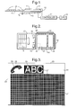
- dots are shaped in the icon area according to the icons which they are to show. Their height is given by the height of the icons according to fig. 3, while their width mainly corresponds to the dot width in the primary display area. If the icon had been shown in the primary display area, it would have had to be composed of a large amount of regular dots of point shape, while the icon when shown in the icon area is composed of a large number of dots "tailored" to the icon concerned, so that will be divided by a large number of thin lines which are not visible to the naked eye in practice.
- the icon area will hereby serve as one or more rows in the dot matrix display in an electrical respect, and the conductive paths to this area are naturally run through the icon area and are also used for selecting dots to form the icons.
- the icon row will thus have a resolution corresponding the dot matrix display in one direction. Dots extend transversely to this direction in the entire width of the icon or in a considerable part of it.
- the invention makes it possible to obtain the traditional system advantages of the icon row - viz. a small number of selectable dots having a good graphic appearance, combined with the possibility of allowing wires from the dot matrix area to pass through the icon area.
- the conductors in the primary and secondary groups of conductive paths are arranged as parallel paths in which the points of intersection form electrodes or switches.
- the paths from the two groups extend transversely to each other, with the voltage-sensitive medium disposed between them. Thus, it is the extent of the electrodes or the switches which determines the shape of the dots.
- An LCD display module of the invention is used in the preferred embodiment in a portable telephone.
- the telephone has a CPU 10 which controls the communication of the telephone with the network with which it communicates.
- the CPU 10 controls the user interface of the telephone - including an LCD display 14.
- the connection between the CPU 10 and the display 14 is via a controller 11 which is mounted onboard, and which serves as an interface between the CPU 10 and two drivers 12, 13 for the rows and columns in the display 14. Otherwise, it will be rather time-consuming to control the drivers 12, 13 directly from the CPU 10, and it will moreover take some programming. The reason is that each bit (dot/pixel) is to be written separately or as quite small groups of e.g.
- the controller 11 and the drivers 12, 13 may be integrated in one and the same chip. Correspondingly, it may be necessary to increase the number of drivers if the display is very large.
- the controller 11 is responsible for i.e. the generation of characters and for the continuous update of the display 14.
- the generation of characters may advantageously be included in the MCU (not shown) of the telephone chip set.
- the controller 11 has an associated (preferably on chip) RAM which is used as a buffer for data from the CPU 10 during the above-mentioned cycle.
- the display 14 will be back-lighted by a plate-shaped lightguide 15 arranged behind the LCD display 14 and in parallel with it.
- the side of the lightguide 15 facing the LCD display 14 is formed with radiation-increasing elements, such as roughnesses in the surface acting as integrated microlenses, or with a holographic element to increase the radiation in the normal direction of the lightguide.
- the lightguide 15 will advantageously be edge-lighted by a plurality of light emitting diodes 16 (LED) and be edge-shaped-converging away from the lighted edge. Uniform radiation from the lightguide may hereby be achieved by increasing the relative radiation with the distance from the lighted edge.
- a keypad 17 having a plurality of keys 18 may adjoin the primary display area of the display 14, the driver 12 of the telephone matrix dots addressed in the longitudinal direction of the telephone being arranged above the display 14.
- the CPU 10 may hereby show the function of keys 19 in the keypad 14 in predetermined areas 20 close to the key 19 concerned if its function depends on the mode of the telephone.
- these predetermined areas 20 will be positioned at the bottom in a primary display area 21 designed as a dot matrix display having regular (e.g. rectangular or square) dots 27.
- an icon area 22 which, in the preferred embodiment, may be regarded electrically as an integrated part of the primary display area 21, as dots in the icon area 22 may be regarded as rows of dots of an irregular shape; their extent in one direction corresponds carefully to that of the other dots in the primary display area 21, while their extent in the transverse direction is icon-specific.
- Fig. 3 schematically illustrates a preferred embodiment of a display image of the invention.
- the primary display area 21 will be shaped as full graphic dot matrix display with e.g. 50 x 100 dots and will have an area of 16 x 32 mm, which gives a resolution of about 80 dpi.
- Dots 27 in the icon area 22 are irregular in shape, and it will be seen that some icons need more dots transversely to the icon row in order to be displayed.
- the resolution in the longitudinal direction of the icon row corresponds to the resolution in the primary display area, while the resolution in the transverse direction varies.
- Display drivers 12, 13 are arranged along the two edges 23 on the display 14.
- the internal light source 15, 16 shown in fig. 1 may easily be modified to utilize incident light instead.
- the rear glass disc instead of being formed with a polarizer having an axis of polarization perpendicular to the axis of polarization of the polarizer on the front glass disc, is provided with a metallic polarizer which, with maintained polarization, reflects the light back through the liquid crystal. The light will thus pass the same polarizer twice, and it will be the influence of the crystal on the polarization of the light en route which will determine which dots are to be dark and light.
- optical property or “optical state” is to be interpreted rather broadly in this context.
- the preferred embodiment uses a voltage-sensitive crystal to change the polarization of the light in a polarizer structure. The same effect may be obtained by controlling the transmission properties of a voltage-sensitive material (high/low absorption) in response to applied voltage.
- the voltage-sensitive material itself may generate the light, as it may be electroluminescent (emit light locally when a voltage is applied locally).
- the present invention includes any novel feature or combination of features disclosed herein either explicitly or any generalisation thereof irrespective of whether or not it relates to the claimed invention or mitigates any or all of the problems addressed.
Landscapes
- Engineering & Computer Science (AREA)
- Computer Vision & Pattern Recognition (AREA)
- Human Computer Interaction (AREA)
- Signal Processing (AREA)
- Physics & Mathematics (AREA)
- Computer Hardware Design (AREA)
- General Physics & Mathematics (AREA)
- Theoretical Computer Science (AREA)
- Devices For Indicating Variable Information By Combining Individual Elements (AREA)
- User Interface Of Digital Computer (AREA)
- Digital Computer Display Output (AREA)
- Liquid Crystal Display Device Control (AREA)
- Control Of Indicators Other Than Cathode Ray Tubes (AREA)
Applications Claiming Priority (2)
| Application Number | Priority Date | Filing Date | Title |
|---|---|---|---|
| GB9702292A GB2321993B (en) | 1997-02-05 | 1997-02-05 | Display with icon row |
| GB9702292 | 1997-02-05 |
Publications (2)
| Publication Number | Publication Date |
|---|---|
| EP0860808A2 true EP0860808A2 (de) | 1998-08-26 |
| EP0860808A3 EP0860808A3 (de) | 2000-02-23 |
Family
ID=10807089
Family Applications (1)
| Application Number | Title | Priority Date | Filing Date |
|---|---|---|---|
| EP98300716A Withdrawn EP0860808A3 (de) | 1997-02-05 | 1998-01-30 | Matrixanzeigevorrichtung mit einer zusätzlichen Ikonenzeile |
Country Status (4)
| Country | Link |
|---|---|
| US (1) | US6236443B1 (de) |
| EP (1) | EP0860808A3 (de) |
| JP (1) | JPH10240203A (de) |
| GB (1) | GB2321993B (de) |
Cited By (1)
| Publication number | Priority date | Publication date | Assignee | Title |
|---|---|---|---|---|
| CN100412930C (zh) * | 2003-05-01 | 2008-08-20 | 三星Sdi株式会社 | 具有高效直流-直流转换器的显示屏驱动装置 |
Families Citing this family (21)
| Publication number | Priority date | Publication date | Assignee | Title |
|---|---|---|---|---|
| KR20000062086A (ko) * | 1999-03-30 | 2000-10-25 | 윤종용 | 휴대폰에서 스피커폰 모드시 음성신호의 송/수신 상태 표시방법 |
| JP3923238B2 (ja) * | 1999-07-07 | 2007-05-30 | シャープ株式会社 | 表示装置 |
| JP3405972B2 (ja) * | 2000-01-11 | 2003-05-12 | 株式会社東芝 | 液晶表示装置 |
| US7054233B2 (en) * | 2001-11-30 | 2006-05-30 | Equity Industries, Inc. | Wall clock with dial illumination |
| KR100438554B1 (ko) * | 2001-11-30 | 2004-07-03 | 엘지전자 주식회사 | 무선단말기의 wml 카드 레이아웃 방법 |
| TWI281997B (en) * | 2002-04-08 | 2007-06-01 | Seiko Instr Inc | Method for checking LCD device |
| JP2003302649A (ja) * | 2002-04-12 | 2003-10-24 | Nec Lcd Technologies Ltd | 液晶表示装置 |
| KR100496304B1 (ko) * | 2003-05-01 | 2005-06-17 | 삼성에스디아이 주식회사 | 효율적인 발진기들을 가진 디스플레이 패널의 구동 장치 |
| JP4785373B2 (ja) * | 2003-11-27 | 2011-10-05 | 株式会社半導体エネルギー研究所 | 表示装置 |
| KR100659065B1 (ko) | 2004-10-12 | 2006-12-19 | 삼성에스디아이 주식회사 | 에너지 재생을 수행하는 전계발광 디스플레이 패널의 구동장치 |
| US20080158210A1 (en) * | 2006-12-28 | 2008-07-03 | Motorola, Inc. | Apparatus and method to display icons and graphic text |
| US7954726B2 (en) * | 2007-06-28 | 2011-06-07 | Honeywell International Inc. | Thermostat with utility messaging |
| US8091794B2 (en) * | 2007-06-28 | 2012-01-10 | Honeywell International Inc. | Thermostat with usage history |
| US7845576B2 (en) * | 2007-06-28 | 2010-12-07 | Honeywell International Inc. | Thermostat with fixed segment display having both fixed segment icons and a variable text display capacity |
| US8185245B2 (en) * | 2010-01-22 | 2012-05-22 | Honeywell International Inc. | HVAC control with utility time of day pricing support |
| US8326466B2 (en) * | 2010-01-22 | 2012-12-04 | Honeywell International Inc. | HVAC control with utility time of day pricing support |
| US8538586B2 (en) * | 2010-01-22 | 2013-09-17 | Honeywell International Inc. | HVAC control with utility time of day pricing support |
| US8204628B2 (en) * | 2010-03-24 | 2012-06-19 | Honeywell International Inc. | Setpoint recovery with utility time of day pricing |
| US10852025B2 (en) | 2013-04-30 | 2020-12-01 | Ademco Inc. | HVAC controller with fixed segment display having fixed segment icons and animation |
| US10649418B2 (en) | 2013-12-11 | 2020-05-12 | Ademco Inc. | Building automation controller with configurable audio/visual cues |
| US10488062B2 (en) | 2016-07-22 | 2019-11-26 | Ademco Inc. | Geofence plus schedule for a building controller |
Citations (1)
| Publication number | Priority date | Publication date | Assignee | Title |
|---|---|---|---|---|
| GB2295917A (en) * | 1994-12-06 | 1996-06-12 | Nec Corp | Liquid crystal display unit |
Family Cites Families (11)
| Publication number | Priority date | Publication date | Assignee | Title |
|---|---|---|---|---|
| CH628490B (de) * | 1978-08-08 | Bbc Brown Boveri & Cie | Elektrooptische anzeigevorrichtung. | |
| US4289383A (en) * | 1979-09-04 | 1981-09-15 | Timex Corporation | Lighted dot matrix display |
| US4435046A (en) | 1980-04-08 | 1984-03-06 | Citizen Watch Company Limited | Liquid crystal display device |
| JPS576882A (en) * | 1980-06-16 | 1982-01-13 | Hitachi Ltd | Liquid crystal display element |
| US4481511A (en) * | 1981-01-07 | 1984-11-06 | Hitachi, Ltd. | Matrix display device |
| GB2119994B (en) * | 1982-05-06 | 1985-08-14 | Conic Semiconductor Limited | Liquid crystal displays |
| JPS59176985A (ja) * | 1983-03-26 | 1984-10-06 | Citizen Watch Co Ltd | 液晶テレビ受信装置 |
| JPH0766248B2 (ja) * | 1985-02-04 | 1995-07-19 | 株式会社日立製作所 | 液晶表示装置及びその駆動方法 |
| FI80536C (fi) | 1988-04-15 | 1990-06-11 | Nokia Mobira Oy | Matrisdisplay. |
| FR2712109B1 (fr) * | 1993-11-04 | 1995-12-15 | Ebauchesfabrik Eta Ag | Dispositif d'affichage à cristaux liquides. |
| GB2291240B (en) * | 1993-11-11 | 1996-07-03 | Seiko Epson Corp | Matrix type display device, electronic system including the same and method of driving such a display device |
-
1997
- 1997-02-05 GB GB9702292A patent/GB2321993B/en not_active Expired - Fee Related
-
1998
- 1998-01-30 EP EP98300716A patent/EP0860808A3/de not_active Withdrawn
- 1998-02-03 US US09/017,826 patent/US6236443B1/en not_active Expired - Fee Related
- 1998-02-04 JP JP2314198A patent/JPH10240203A/ja active Pending
Patent Citations (1)
| Publication number | Priority date | Publication date | Assignee | Title |
|---|---|---|---|---|
| GB2295917A (en) * | 1994-12-06 | 1996-06-12 | Nec Corp | Liquid crystal display unit |
Cited By (1)
| Publication number | Priority date | Publication date | Assignee | Title |
|---|---|---|---|---|
| CN100412930C (zh) * | 2003-05-01 | 2008-08-20 | 三星Sdi株式会社 | 具有高效直流-直流转换器的显示屏驱动装置 |
Also Published As
| Publication number | Publication date |
|---|---|
| GB9702292D0 (en) | 1997-03-26 |
| EP0860808A3 (de) | 2000-02-23 |
| US6236443B1 (en) | 2001-05-22 |
| GB2321993B (en) | 2001-02-28 |
| GB2321993A (en) | 1998-08-12 |
| JPH10240203A (ja) | 1998-09-11 |
Similar Documents
| Publication | Publication Date | Title |
|---|---|---|
| US6236443B1 (en) | Display with icon row | |
| CN110231735B (zh) | 显示装置 | |
| KR100868159B1 (ko) | 조명 장치 및 그것을 이용한 액정 표시 장치 | |
| CN100561320C (zh) | 液晶装置及电子设备 | |
| KR100523097B1 (ko) | 조명 장치, 액정 장치 및 전자 기기 | |
| US8698703B2 (en) | Electro-optical device having parallax barrier system | |
| US20020145860A1 (en) | Backlight assembly and liquid crystal display device using thereof | |
| US20020126240A1 (en) | Liquid crystal display | |
| CN114613829A (zh) | 显示面板以及显示装置 | |
| US20070030240A1 (en) | Display device, method, and terminal device having switchable viewing angle | |
| TWI287656B (en) | Electro-optical device substrate, electro-optical device, and electronic apparatus | |
| KR20050112878A (ko) | 전기 영동 표시 장치 | |
| CN109828402A (zh) | 液晶显示面板和显示装置 | |
| JPH1195693A (ja) | 表示装置 | |
| KR100550487B1 (ko) | 액정 표시 장치 | |
| CN100483200C (zh) | 液晶显示装置 | |
| US8233124B2 (en) | Liquid crystal display device | |
| JP4186901B2 (ja) | 照明装置、電気光学装置及び電子機器 | |
| JP2008064790A (ja) | ディスプレイおよびそれに用いられる視野角制御装置 | |
| KR20090098886A (ko) | Pdlc를 이용하는 2차 디스플레이 | |
| US7436470B2 (en) | Display device having liquid crystal layer and switchable optical layer | |
| JP3659025B2 (ja) | 表示装置 | |
| CN210119640U (zh) | 一种液晶显示面板及显示装置 | |
| KR100936960B1 (ko) | 반사투과형 액정표시장치 | |
| KR100699158B1 (ko) | 액정표시장치, 그 구동방법 및 이를 구비한 이동통신 단말기 |
Legal Events
| Date | Code | Title | Description |
|---|---|---|---|
| PUAI | Public reference made under article 153(3) epc to a published international application that has entered the european phase |
Free format text: ORIGINAL CODE: 0009012 |
|
| AK | Designated contracting states |
Kind code of ref document: A2 Designated state(s): DE FR GB SE |
|
| AX | Request for extension of the european patent |
Free format text: AL;LT;LV;MK;RO;SI |
|
| PUAL | Search report despatched |
Free format text: ORIGINAL CODE: 0009013 |
|
| AK | Designated contracting states |
Kind code of ref document: A3 Designated state(s): AT BE CH DE DK ES FI FR GB GR IE IT LI LU MC NL PT SE |
|
| AX | Request for extension of the european patent |
Free format text: AL;LT;LV;MK;RO;SI |
|
| 17P | Request for examination filed |
Effective date: 20000823 |
|
| AKX | Designation fees paid |
Free format text: DE FR GB SE |
|
| 17Q | First examination report despatched |
Effective date: 20011227 |
|
| RAP1 | Party data changed (applicant data changed or rights of an application transferred) |
Owner name: NOKIA CORPORATION |
|
| STAA | Information on the status of an ep patent application or granted ep patent |
Free format text: STATUS: THE APPLICATION IS DEEMED TO BE WITHDRAWN |
|
| 18D | Application deemed to be withdrawn |
Effective date: 20020506 |