EP0860892B1 - Récepteur radio à stabilisation de connecteur d'antenne - Google Patents
Récepteur radio à stabilisation de connecteur d'antenne Download PDFInfo
- Publication number
- EP0860892B1 EP0860892B1 EP19980101133 EP98101133A EP0860892B1 EP 0860892 B1 EP0860892 B1 EP 0860892B1 EP 19980101133 EP19980101133 EP 19980101133 EP 98101133 A EP98101133 A EP 98101133A EP 0860892 B1 EP0860892 B1 EP 0860892B1
- Authority
- EP
- European Patent Office
- Prior art keywords
- radio receiver
- antenna
- broadcast radio
- connection box
- housing
- Prior art date
- Legal status (The legal status is an assumption and is not a legal conclusion. Google has not performed a legal analysis and makes no representation as to the accuracy of the status listed.)
- Expired - Lifetime
Links
- 230000006641 stabilisation Effects 0.000 title 1
- 238000001746 injection moulding Methods 0.000 claims description 4
- 230000013011 mating Effects 0.000 claims description 2
- 238000012216 screening Methods 0.000 claims 1
- 238000004519 manufacturing process Methods 0.000 description 3
- 230000008878 coupling Effects 0.000 description 1
- 238000010168 coupling process Methods 0.000 description 1
- 238000005859 coupling reaction Methods 0.000 description 1
- 230000001419 dependent effect Effects 0.000 description 1
- 238000001514 detection method Methods 0.000 description 1
- 238000010586 diagram Methods 0.000 description 1
- 238000002347 injection Methods 0.000 description 1
- 239000007924 injection Substances 0.000 description 1
- 239000002184 metal Substances 0.000 description 1
Images


Classifications
-
- H—ELECTRICITY
- H01—ELECTRIC ELEMENTS
- H01Q—ANTENNAS, i.e. RADIO AERIALS
- H01Q21/00—Antenna arrays or systems
- H01Q21/30—Combinations of separate antenna units operating in different wavebands and connected to a common feeder system
-
- H—ELECTRICITY
- H01—ELECTRIC ELEMENTS
- H01Q—ANTENNAS, i.e. RADIO AERIALS
- H01Q1/00—Details of, or arrangements associated with, antennas
- H01Q1/12—Supports; Mounting means
- H01Q1/1207—Supports; Mounting means for fastening a rigid aerial element
-
- H—ELECTRICITY
- H01—ELECTRIC ELEMENTS
- H01R—ELECTRICALLY-CONDUCTIVE CONNECTIONS; STRUCTURAL ASSOCIATIONS OF A PLURALITY OF MUTUALLY-INSULATED ELECTRICAL CONNECTING ELEMENTS; COUPLING DEVICES; CURRENT COLLECTORS
- H01R2201/00—Connectors or connections adapted for particular applications
- H01R2201/02—Connectors or connections adapted for particular applications for antennas
Definitions
- the invention is based on a radio receiver according to the preamble of the main claim.
- the radio receiver according to the invention with the features of the main claim has the advantage that a single antenna connection module with defined Antennenbuchsenpositionen is providable, which is only on the receiver side to adapt to the respective device type, but antenna side standardized antenna sockets and terminal positions may have. That way expensive cable tails outside the housing of the radio receiver not only for the radio receiving part but also for other integrated in the radio receiver receiving parts, for example, for mobile and position detection receiver avoided.
- junction box is not integrated into the housing of the radio receiver, but is positively connected thereto.
- Another advantage is also that an antenna terminal, the cable-shaped from the back or
- connection box has an outer holding device and that in the outer holding device, an antenna tube in particular for broadcast reception is feasible.
- an antenna can be stabilized in position by the terminal box additionally.
- the at least one antenna socket on the junction box and the connecting line are fixed by holding devices in the junction box in position.
- the at least one antenna socket and the connecting line is further stabilized, so that in particular the axial forces are absorbed by the terminal box, the at least one antenna socket and the connecting line are not loaded and therefore wear less.
- terminal box is bolted to the back or side wall of the radio receiver. In this way, a simple way to connect the junction box with the Ge Reifenück- or side wall of the radio receiver is given.
- junction box is formed in two pieces from a preferably manufactured by injection molding part and a preferably also made of injection molded closure cap. In this way, the junction box is also very stable and wear.
- junction box is RF moderately shielded. In this way, the coupling of high-frequency interference is prevented at the junction box.
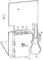
- FIG. 1 shows a front view of a junction box
- Figure 2 shows a screwed to the rear wall of a radio receiver terminal box
- Figure 3 is a rear view of a junction box
- Figure 4 is an interior view of a junction box without closure cap
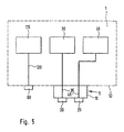
- Figure 5 is a block diagram of a radio receiver according to the invention.
- a radio receiver formed as a car radio having a broadcast receiving section 115, a radio telephone 30 and a receiver 40 for detecting position, which is formed in the present embodiment as a GPS receiver (Global Positioning System). Further modules of the data input and output of the radio receiver 1 are executed in a manner known to those skilled in the art and not shown in FIG.
- a first antenna socket 60 for the radio reception part 115 is arranged and connected to the radio reception part 115 via a first connecting line 120.
- an antenna terminal 5 is arranged, which comprises a junction box 15 with a second antenna socket 20 and a third antenna socket 25.
- the second antenna socket 20 is connected via a second connecting line 35 to the radio telephone 30 and the third antenna socket 25 is connected via a third connecting line 45 to the GPS receiver 40.
- the junction box 15 is shown. It consists of a housing part 85 and a closure lid 90. Clearly the junction box 15 is cuboid-shaped, wherein the closure lid 90 covers a longitudinal side of the junction box 15. According to Figure 2, the junction box 15 is bolted to its closure cover 90 via a on the opposite side of the closure cap 90 side of the junction box 15 screw 100 with the rear wall 10 of the radio receiver 1 frictionally. In this case, other non-positive connection types, such as bonding are possible. On one of its narrow sides, the connection box 15 has the second antenna socket 20 and the third antenna socket 25, which enable a space-saving feed of the respective antenna cable in parallel or at a small angle to the rear wall 10 of the housing.
- connection box 15 has on an additional narrow side an outer holding device 50, which holds an antenna tube 55 for radio reception in also to the rear wall 10 parallel guide or small angle according to Figure 2.
- the antenna tube 55 is angled at right angles at the level of the first antenna socket 60 and connected to the first antenna socket 60 on the rear wall 10 of the radio receiver 1.
- FIG. 3 shows a rear view of the connection box 15.
- a screw opening 110 for receiving the screw 100 is shown in the closure lid 90.
- a plug module 95 can be seen on the closure lid 90, via which the second connecting line 35 is connected to a mating plug contact of the rear wall 10 of the radio receiver 1. From an opening 125 of the closure lid 90 also protrudes the third connecting line 45, which has a Opening the housing rear wall 10 is guided to the GPS receiver 40.
- FIG. 4 the interior of the junction box 15 and the housing part 85 is shown.
- the housing part 85 on the narrow side with the two antenna sockets 20, 25 on a first antenna book aperture 130 and a second antenna book aperture 135.
- the first antenna bushing breakthrough 130 serves to receive the second antenna socket 20
- the second antenna bushing breakthrough 135 serves to receive the third antenna bushing 25.
- the second antenna bushing 20 is additionally supported by a first holding device 65 in the interior of the housing part 85 3
- the plug-in module 95 is connected to the second antenna socket 20 via the second connecting line 35 according to FIG. 4 and is stabilized in the housing part 85 via a second holding device 70.
- the first holding device 65 engages around the cylindrical second antenna socket 20 by correspondingly bent webs, which are opposite one another and are connected to the longitudinal side of the housing part 85 facing away from the closure lid 90.
- the second holding device 70 encloses the plug module 95 annularly and is likewise connected to the longitudinal side of the housing part 85 opposite the closure lid 90.
- the third connecting line 45 is guided in the housing part 85 by a third holding device 75 in the form of a cable channel.
- the also circular cylindrical third antenna socket 25 is fixed by a fourth holding device 80 in the housing part 85 in position.
- the fourth holding device 80 encloses the third antenna socket 25 likewise by means of two longitudinal sides of the housing part 85 opposite one another and opposite the closure lid 90 connected webs.
- a cylindrical screw guide 105 is further arranged, which serves to receive the screw 100.
- connection box 15 may also be arranged on a housing side wall of the radio receiver 1.
- the housing part 85 and the closure lid 90 are preferably made of injection molding.
- the housing part 85 can be glued to the closure lid 90 or welded or connected in any other way.
- a connection of the housing part 85 with the closure lid 90 is also given when both parts are connected via the screw 100 frictionally connected to the rear wall 10 of the radio receiver 1.
- an insert part 200 made of metal or bimetal for high-frequency shielding is arranged in the connection box 15, which is otherwise made of plastic.
- the connection box 15 which is otherwise made of plastic.
- connection box 15 can be equipped with the necessary antenna sockets.
- the first antenna socket 60 for the radio receiving part 115 may be disposed in the terminal box 15.
Landscapes
- Details Of Aerials (AREA)
- Structure Of Receivers (AREA)
- Fittings On The Vehicle Exterior For Carrying Loads, And Devices For Holding Or Mounting Articles (AREA)
Claims (7)
- Récepteur radio (1), en particulier autoradio, auquel est intégré au moins un autre récepteur (30, 40) destiné de préférence à un téléphone radio ou à une détermination de position, avec un connecteur d'antenne (5) sur une paroi latérale ou arrière de boîtier (10) de ce récepteur radio (1),
caractérisé en ce que- le connecteur d'antenne (5) est parallèle à la paroi latérale ou arrière de boîtier (10) ou faiblement inclinée par rapport à celle-ci, ce connecteur (5) comprenant un boîtier de connecteur (15) présentant au moins une douille d'antenne (20, 25) de l'autre récepteur (30, 40) au nombre d'un au moins,- la douille d'antenne (20, 25) au nombre d'une au moins est montée sur un côté étroit du boîtier de connecteur, elle est parallèle ou faiblement inclinée par rapport à la paroi latérale ou arrière de boîtier (10), sur laquelle est monté le boîtier de connecteur (15), et- cette douille est raccordée par un conducteur de liaison (35, 45) à l'autre récepteur (30, 40) au nombre d'un au moins,- le boîtier de connecteur (15) étant relié avec verrouillage par friction à la paroi latérale ou arrière de boîtier (10) du récepteur radio (1). - Récepteur radio (1) selon la revendication 1,
caractérisé en ce que
le boîtier de connecteur (15) présente un dispositif de maintien (50) externe et un tube d'antenne (55) peut être introduit dans ce dispositif, externe (50) en particulier pour la réception radio. - Récepteur radio (1) selon la revendication 1 ou 2,
caractérisé en ce que
la douille d'antenne (20, 25) au nombre d'une au moins est fixée sur le boîtier de connecteur (15) et le conducteur de liaison (35, 45) est fixé en position dans le boîtier de connecteur (15) par des dispositifs de maintien (65, 70, 75, 80). - Récepteur radio (1) selon la revendication 1, 2 ou 3,
caractérisé en ce que
le boîtier de connecteur (15) est vissé sur la paroi latérale ou arrière de boîtier (10) du récepteur radio. - Récepteur radio (1) selon une des revendications précédentes,
caractérisé en ce que
le boîtier de connecteur (15) est constitué de deux parties réalisées de préférence par injection, à savoir une partie de boîtier (85) et une partie de couvercle (90). - Récepteur radio (1) selon une des revendications précédentes,
caractérisé en ce que
le conducteur de liaison (35, 45) est relié par l'intermédiaire d'un module enfichable (95) à un contact de contre fiche prévu sur la paroi latérale ou arrière de boîtier (10) du récepteur radio (1). - Récepteur radio (1) selon une des revendications précédentes,
caractérisé en ce que
le boîtier de connecteur (15) présente un blindage anti HF.
Applications Claiming Priority (2)
| Application Number | Priority Date | Filing Date | Title |
|---|---|---|---|
| DE19706709 | 1997-02-20 | ||
| DE1997106709 DE19706709C2 (de) | 1997-02-20 | 1997-02-20 | Rundfunkempfänger |
Publications (3)
| Publication Number | Publication Date |
|---|---|
| EP0860892A2 EP0860892A2 (fr) | 1998-08-26 |
| EP0860892A3 EP0860892A3 (fr) | 2000-07-19 |
| EP0860892B1 true EP0860892B1 (fr) | 2006-03-29 |
Family
ID=7820932
Family Applications (1)
| Application Number | Title | Priority Date | Filing Date |
|---|---|---|---|
| EP19980101133 Expired - Lifetime EP0860892B1 (fr) | 1997-02-20 | 1998-01-23 | Récepteur radio à stabilisation de connecteur d'antenne |
Country Status (2)
| Country | Link |
|---|---|
| EP (1) | EP0860892B1 (fr) |
| DE (2) | DE19706709C2 (fr) |
Families Citing this family (1)
| Publication number | Priority date | Publication date | Assignee | Title |
|---|---|---|---|---|
| DE10352169A1 (de) * | 2003-11-05 | 2005-06-09 | Siemens Ag | Adapter für Autoradios |
Family Cites Families (5)
| Publication number | Priority date | Publication date | Assignee | Title |
|---|---|---|---|---|
| US4881910A (en) * | 1987-09-21 | 1989-11-21 | Walter Odemer Co., Inc. | Quick release minimum profile shuttle for vehicle radios and tape players |
| GB2249447B (en) * | 1990-10-30 | 1995-05-24 | Technophone Ltd | Combined broadcast radio receiver and radio telephone |
| IT221697Z2 (it) * | 1991-02-27 | 1994-09-15 | Siria Srl | Dispositivo di collegamento d'antenna per autoradio |
| JP2793380B2 (ja) * | 1991-06-17 | 1998-09-03 | 富士通株式会社 | 同軸マルチ混在コネクタ |
| DE19644648C1 (de) * | 1996-10-26 | 1998-05-20 | Bosch Gmbh Robert | Rundfunkempfänger |
-
1997
- 1997-02-20 DE DE1997106709 patent/DE19706709C2/de not_active Expired - Fee Related
-
1998
- 1998-01-23 EP EP19980101133 patent/EP0860892B1/fr not_active Expired - Lifetime
- 1998-01-23 DE DE59813464T patent/DE59813464D1/de not_active Expired - Lifetime
Also Published As
| Publication number | Publication date |
|---|---|
| DE19706709A1 (de) | 1998-09-03 |
| DE59813464D1 (de) | 2006-05-18 |
| EP0860892A2 (fr) | 1998-08-26 |
| EP0860892A3 (fr) | 2000-07-19 |
| DE19706709C2 (de) | 2003-12-18 |
Similar Documents
| Publication | Publication Date | Title |
|---|---|---|
| DE112016007671B4 (de) | Verbinderanordnung | |
| DE102008050111B3 (de) | Steckverbinder-Buchsenanordnung für die Daten- und Kommunikationstechnik | |
| DE60205562T2 (de) | Richtungsfreie Zündpille-Anschlusseinrichtung für Kraftfahrzeug-Luftsacksysteme | |
| DE10393763B4 (de) | Verbinderanordnung mit einer dielektrischen Abdeckung | |
| DE102011117475A1 (de) | Motor | |
| WO2007131826A1 (fr) | Dispositif de fixation et procédé de fixation pour une antenne de véhicule | |
| DE9314256U1 (de) | Drahtlos gesteuerte Wegfahrsperre für ein Kraftfahrzeug | |
| EP0957371A2 (fr) | Capteur radar | |
| EP3679211A1 (fr) | Ensemble formant poignée de portière de véhicule automobile intégrant un système électronique | |
| DE19842427C2 (de) | Antenne für eine Sende- und/oder Empfangseinheit eines Diebstahlschutzsystems eines Kraftfahrzeugs | |
| DE202008004580U1 (de) | Vorrichtung zur Aufnahme eines mobilen Endgerätes | |
| EP4096034B1 (fr) | Connecteur enfichable pour un appareil électronique de commande et appareil de commande | |
| DE19729854C2 (de) | Vorrichtung zum Anschluß einer Außenantenne | |
| EP0860892B1 (fr) | Récepteur radio à stabilisation de connecteur d'antenne | |
| EP1447878A1 (fr) | Antenne pour un verrouillage radio centralisé | |
| DE19647925C1 (de) | Kabelverbinder | |
| EP0932522B1 (fr) | Recepteur radio | |
| EP2991165B1 (fr) | Connecteur a fiches electrique, element de connecteur a fiche et utilisation | |
| DE102015016467A1 (de) | Kraftfahrzeugtürgriff mit integrierter Elektronikbaugruppe | |
| EP3465818B1 (fr) | Dispositif de communication pour système de diagnostic d'un véhicule automobile | |
| DE60033741T2 (de) | Koaxialer Verbinder | |
| DE102017206632B3 (de) | Wandlervorrichtung zur Anpassung einer Antennenimpedanz mit Gehäuse für ein Kraftfahrzeug und Kraftfahrzeug mit eingebauter Wandlervorrichtung | |
| EP1811613A1 (fr) | Connecteur, de préférence Fakra Standard connecteur à angle droi droit, pour des applications véhicules | |
| EP1471603A2 (fr) | Antenne dans une grille d'aération d'un véhicule | |
| DE102023109638A1 (de) | Hybrides Steckverbindergehäuse |
Legal Events
| Date | Code | Title | Description |
|---|---|---|---|
| PUAI | Public reference made under article 153(3) epc to a published international application that has entered the european phase |
Free format text: ORIGINAL CODE: 0009012 |
|
| AK | Designated contracting states |
Kind code of ref document: A2 Designated state(s): DE FR IT |
|
| PUAL | Search report despatched |
Free format text: ORIGINAL CODE: 0009013 |
|
| AK | Designated contracting states |
Kind code of ref document: A3 Designated state(s): AT BE CH DE DK ES FI FR GB GR IE IT LI LU MC NL PT SE |
|
| RIC1 | Information provided on ipc code assigned before grant |
Free format text: 7H 01Q 1/12 A, 7H 01Q 21/30 B |
|
| 17P | Request for examination filed |
Effective date: 20010119 |
|
| AKX | Designation fees paid |
Free format text: DE FR IT |
|
| 17Q | First examination report despatched |
Effective date: 20030827 |
|
| GRAP | Despatch of communication of intention to grant a patent |
Free format text: ORIGINAL CODE: EPIDOSNIGR1 |
|
| GRAS | Grant fee paid |
Free format text: ORIGINAL CODE: EPIDOSNIGR3 |
|
| GRAA | (expected) grant |
Free format text: ORIGINAL CODE: 0009210 |
|
| AK | Designated contracting states |
Kind code of ref document: B1 Designated state(s): DE FR IT |
|
| PG25 | Lapsed in a contracting state [announced via postgrant information from national office to epo] |
Ref country code: IT Free format text: LAPSE BECAUSE OF FAILURE TO SUBMIT A TRANSLATION OF THE DESCRIPTION OR TO PAY THE FEE WITHIN THE PRE;WARNING: LAPSES OF ITALIAN PATENTS WITH EFFECTIVE DATE BEFORE 2007 MAY HAVE OCCURRED AT ANY TIME BEFORE 2007. THE CORRECT EFFECTIVE DATE MAY BE DIFFERENT FROM THE ONE RECORDED.SCRIBED TIME-LIMIT Effective date: 20060329 |
|
| REF | Corresponds to: |
Ref document number: 59813464 Country of ref document: DE Date of ref document: 20060518 Kind code of ref document: P |
|
| ET | Fr: translation filed | ||
| PLBE | No opposition filed within time limit |
Free format text: ORIGINAL CODE: 0009261 |
|
| STAA | Information on the status of an ep patent application or granted ep patent |
Free format text: STATUS: NO OPPOSITION FILED WITHIN TIME LIMIT |
|
| 26N | No opposition filed |
Effective date: 20070102 |
|
| PGFP | Annual fee paid to national office [announced via postgrant information from national office to epo] |
Ref country code: IT Payment date: 20110129 Year of fee payment: 14 |
|
| PG25 | Lapsed in a contracting state [announced via postgrant information from national office to epo] |
Ref country code: IT Free format text: LAPSE BECAUSE OF NON-PAYMENT OF DUE FEES Effective date: 20120123 |
|
| PGFP | Annual fee paid to national office [announced via postgrant information from national office to epo] |
Ref country code: FR Payment date: 20130207 Year of fee payment: 16 |
|
| REG | Reference to a national code |
Ref country code: FR Ref legal event code: ST Effective date: 20140930 |
|
| PG25 | Lapsed in a contracting state [announced via postgrant information from national office to epo] |
Ref country code: FR Free format text: LAPSE BECAUSE OF NON-PAYMENT OF DUE FEES Effective date: 20140131 |
|
| PGFP | Annual fee paid to national office [announced via postgrant information from national office to epo] |
Ref country code: DE Payment date: 20160322 Year of fee payment: 19 |
|
| REG | Reference to a national code |
Ref country code: DE Ref legal event code: R119 Ref document number: 59813464 Country of ref document: DE |
|
| PG25 | Lapsed in a contracting state [announced via postgrant information from national office to epo] |
Ref country code: DE Free format text: LAPSE BECAUSE OF NON-PAYMENT OF DUE FEES Effective date: 20170801 |