EP0860912A2 - Mécanisme de coupage et de dénudage de fils - Google Patents
Mécanisme de coupage et de dénudage de fils Download PDFInfo
- Publication number
- EP0860912A2 EP0860912A2 EP98301272A EP98301272A EP0860912A2 EP 0860912 A2 EP0860912 A2 EP 0860912A2 EP 98301272 A EP98301272 A EP 98301272A EP 98301272 A EP98301272 A EP 98301272A EP 0860912 A2 EP0860912 A2 EP 0860912A2
- Authority
- EP
- European Patent Office
- Prior art keywords
- wire
- cutting
- blades
- insulation
- eject
- Prior art date
- Legal status (The legal status is an assumption and is not a legal conclusion. Google has not performed a legal analysis and makes no representation as to the accuracy of the status listed.)
- Withdrawn
Links
- 230000007246 mechanism Effects 0.000 title abstract description 11
- 238000009413 insulation Methods 0.000 claims abstract description 28
- 241000237858 Gastropoda Species 0.000 claims abstract description 5
- 230000000694 effects Effects 0.000 claims abstract 3
- 230000000712 assembly Effects 0.000 abstract description 16
- 238000000429 assembly Methods 0.000 abstract description 16
- 238000000034 method Methods 0.000 description 10
- 125000006850 spacer group Chemical group 0.000 description 3
- 238000010008 shearing Methods 0.000 description 2
- 238000009825 accumulation Methods 0.000 description 1
- 230000003466 anti-cipated effect Effects 0.000 description 1
- 230000005484 gravity Effects 0.000 description 1
- 230000007257 malfunction Effects 0.000 description 1
- 238000004519 manufacturing process Methods 0.000 description 1
Images



Classifications
-
- H—ELECTRICITY
- H01—ELECTRIC ELEMENTS
- H01R—ELECTRICALLY-CONDUCTIVE CONNECTIONS; STRUCTURAL ASSOCIATIONS OF A PLURALITY OF MUTUALLY-INSULATED ELECTRICAL CONNECTING ELEMENTS; COUPLING DEVICES; CURRENT COLLECTORS
- H01R43/00—Apparatus or processes specially adapted for manufacturing, assembling, maintaining, or repairing of line connectors or current collectors or for joining electric conductors
- H01R43/04—Apparatus or processes specially adapted for manufacturing, assembling, maintaining, or repairing of line connectors or current collectors or for joining electric conductors for forming connections by deformation, e.g. crimping tool
- H01R43/048—Crimping apparatus or processes
- H01R43/05—Crimping apparatus or processes with wire-insulation stripping
-
- B—PERFORMING OPERATIONS; TRANSPORTING
- B21—MECHANICAL METAL-WORKING WITHOUT ESSENTIALLY REMOVING MATERIAL; PUNCHING METAL
- B21F—WORKING OR PROCESSING OF METAL WIRE
- B21F11/00—Cutting wire
-
- H—ELECTRICITY
- H01—ELECTRIC ELEMENTS
- H01R—ELECTRICALLY-CONDUCTIVE CONNECTIONS; STRUCTURAL ASSOCIATIONS OF A PLURALITY OF MUTUALLY-INSULATED ELECTRICAL CONNECTING ELEMENTS; COUPLING DEVICES; CURRENT COLLECTORS
- H01R43/00—Apparatus or processes specially adapted for manufacturing, assembling, maintaining, or repairing of line connectors or current collectors or for joining electric conductors
- H01R43/28—Apparatus or processes specially adapted for manufacturing, assembling, maintaining, or repairing of line connectors or current collectors or for joining electric conductors for wire processing before connecting to contact members, not provided for in groups H01R43/02 - H01R43/26
Definitions
- the present invention relates to wire processing machines and more particularly to an improved mechanism for cutting a wire to length and stripping the insulation from the cut ends.
- a machine and method are disclosed for processing an insulated wire, to sever the wire into a feed end and an eject end, and to remove a selected portion of insulation from at least one of the feed end and the eject end.
- the machine includes a wire cutting and stripping unit including a first left blade having a first cutting edge, a second left blade having a second cutting edge, a first right blade having a third cutting edge, and a second right blade having a fourth cutting edge.
- the first and second left blades are attached to a left holder and the first and second right blades are attached to a right holder.
- a wire feed unit is provided for moving the wire along a wire path between the first and third cutting edges in a first direction and in a second opposite direction.
- Machines that utilize electrical wire in the manufacture of a product typically draw lengths of wire from an endless source, such as a reel, and feed the drawn wire into mechanisms that operate on the wire in some way to produce the product. Sometimes the wire is cut to a specific length and it becomes the product, other times the wire is used to interconnect electrical components in a product.
- the former for example, is made by a machine that is typically called a "lead maker" in the industry. These machines draw wire from an endless source, measure its length precisely, then cut it to a desired length. The ends may or may not be terminated to electrical terminals, or the ends may simply be prepared for termination.
- a wire cutting and stripping unit having a set of cutting blades for cutting the wire and a separate set of stripping blades for stripping a desired length of insulation from the ends of the wire, as may be required.
- the wire cutting blades and the stripping blades are fixed in a common tool holder that is movable toward and away from the wire path. The cutting blades extend further outwardly so that as the tool holder is advanced toward the wire, the cutting blades engage and cut the wire followed immediately by the stripping blades engaging the wire and severing the insulation. The wire is then pulled axially away from the cutting and stripping unit so that the cut slug of insulation is stripped away from the wire.
- This arrangement requires that the stripping blades be spaced from the cutting blades a predetermined distance that corresponds to the desired length of the strip.
- the spacing between the stripping blades and the cutting blades must be adjusted, usually by inserting or removing spacers. This requires that the machine be taken out of service while this is done. There is usually insufficient room between the cutting blades and the stripping blades to provide a scrap collection system, so the stripped slug is allowed to simply fall downwardly by gravity. This sometimes causes large amounts of scrap to accumulate in the machine that is difficult to remove and may cause a malfunction.
- a mechanism has been used to advance the tool holder toward the wire in two distinct steps.
- the wire is severed and the advancement of the tool holder is momentarily stopped.
- the wire is then repositioned axially with respect to the stripping blades by the wire feed system.
- the mechanism then resumes moving the tool holder so that the stripping blades engage and sever the insulation at the desired place and, as above, the wire is withdrawn axially to strip away the slug of insulation.
- This machine has the advantage that the strip length is controllable through automation so that wires having different strip length requirements can be processed by the lead maker in succession without stopping the machine for adjustment. While this structure is advantageous, an important drawback is that three pairs of cutting blades must be used, one pair for severing the wire and two other pairs positioned on opposite sides of the severing blades for cutting the insulation when stripping. This requires suitable mounting structures for the six blades that accurately position them and move them into engagement with the wire, resulting in a relatively expensive and complex mechanism. Further, when the machine is reconfigured to process wire of a different gage the two pairs of stripping blades must be replaced with blades of a size corresponding to the different gage. Additionally, the problem of scrap accumulation is not addressed.
- What is needed is a simple and inexpensive wire cutting and stripping unit having only two pairs of cutting blades for each gage of wire that both sever the wire and then engage the two severed ends and cut the insulation preparatory to stripping. Additionally, the unit should include additional pairs of cutting blades that are automatically positionable for accommodating anticipated different wire gage sizes. When the cut insulation is stripped from the cut ends of the wire, a scrap collection device should be adjacent the stripping blades to capture the stripped slug.
- the machine and method of the present invention address the above problems by processing an insulated wire, severing the wire into a feed end and an eject end, and removing a selected portion of insulation from at least one of the feed end and the eject end.
- the machine includes a wire cutting and stripping unit including a first left blade having a first cutting edge, a second left blade having a second cutting edge, a first right blade having a third cutting edge, and a second right blade having a fourth cutting edge.
- the first and second left blades are attached to a left holder and the first and second right blades are attached to a right holder.
- a wire feed unit is provided for moving the wire along a wire path between the first and third cutting edges in a first direction and in a second opposite direction.
- a drive unit is provided for moving the left and right holders in third and fourth opposite directions, respectively, so that the first left and first right blades converge toward each other and the first and third cutting edges sever the wire.
- the left and right holders are further moved in the third and fourth directions so that the first right and second left blades converge and the second and third cutting edges move into insulation cutting engagement with the feed side end, and the first left and second right blades converge and the first and fourth cutting edges move into insulation cutting engagement with the eject side end.
- FIG. 1 a wire processing machine 10 for receiving a continuous length of wire 12 in the making of electrical leads 14.
- the machine 10 includes a frame 16 and a wire inlet assembly 18 attached to the frame which straightens the wire and feeds it into the processing portion of the machine along a wire path 19.
- a feed side wire transfer unit 20 is arranged to position the wire with respect to a wire cutting and stripping unit 22 for cutting the lead 14 to length and for stripping the insulation from the cut ends of the wire 12 and lead 14, as desired. Additionally, the feed side transfer unit 20 will position the cut end of the wire 12 in terminating tooling held by a feed side terminating unit 24 for attachment of a terminal, if required.
- the partially completed lead 14 is then received by an eject side transfer unit 26 which positions the cut end of the lead in terminating tooling held by an eject side terminating unit 28 for attachment of a terminal, if required.
- the completed lead is then ejected into a stacking tray 30, as shown in Figure 1.
- the wire cutting and stripping unit 22 includes a housing 32 having a pair of mounting flanges 34 on opposite sides which are secured to the frame 16 by means of screws 36 extending through clearance holes in the flanges and into threaded holes in the frame 16.
- a stationary shaft 38 extends between two opposite walls of the housing 32, spanning the interior 40, as best seen in Figure 3.
- Right and left cutting blade holder assemblies 42 and 44, respectively, are journaled for rotation on the stationary shaft 38 by means of bearings 46 and 46' arranged in a bore in each holder assembly.
- the right and left cutting blade holder assemblies 42 and 44 are shown in Figures 4 through 7. These two holder assemblies are substantially similar in structure, therefore, only the right holder assembly 42 will be described in detail. Parts in the left holder assembly 44 will have corresponding identifying numbers to similar parts of the right holder assembly 42, but will be primed.
- the holder assembly 42 includes a disc-shaped holder 52 and attached hub 54 extending from one side thereof.
- the hub 54 includes timing belt notches or teeth 56 on its outer periphery for a purpose that will be explained.
- Three pairs of cutting and stripping blades 58,59; 60,61; and 62,63 are arranged in closely conformal slots 64 that are disposed in a flat face 66 of the disc-shaped holder 52.
- each cutting and stripping blade includes a relatively thick shank portion 70 that is disposed within the slot 64 through which the threaded hole extends, as best seen in Figure 3.
- Each of the cutting and stripping blades 58, 59, 60, 61, 62, and 63 includes a flat surface 72 that lies in a plane 74 that is perpendicular to the stationary shaft 38.
- Each of the cutting and stripping blades 58, 59, 60, 61, 62, and 63 has a V-shaped cutting edge 80 having a rake back or relief 82 facing away from the flat surface 72, as best seen in Figures 4 and 6.
- the V-shaped cutting edges 80 of the blades 58 and 59 converge to a vertex radius 84 sized for a 16 gage wire
- the cutting edges 80 of the blades 60 and 61 converge to a vertex radius 86 sized for an 18 gage wire
- the cutting edges 80 of the blades 62 and 63 converge to a vertex radius 88 sized for a 20 gage wire.
- the four cutting and stripping blades 58, 59, 58', and 59' will be used in combination to process 16 gage wires, while the other two sets of four blades 60, 61, 60', 61' and 62, 63, 62', 63' will be similarly used to process 18 and 20 gage wires, respectively.
- the right and left holder assemblies 42 and 44 are arranged on the stationary shaft 38 with a spacer 90 between the housing 32 and each hub 56 and 56'.
- the spacers 90 have a thickness that minimizes end play of the two holder assemblies and maintains the flat surfaces 72 and 72' in close wire shearing engagement, as shown in Figure 3. In this position the two planes 74 and 74' are very nearly coplanar.
- each blade 58 through 63 and 58' through 63' includes chamfered edges 92 and 92', respectively, as shown in Figures 4 and 6, to prevent possible interference as the blades of the right holder assembly 42 begin to engage the blades of the left holder assembly 44.
- the wire cutting and stripping unit 22 includes first and second parallel drive shafts 96 and 98, respectively, journaled for rotation in bearings 100 that are disposed in two opposite side walls of the housing 32.
- the first drive shaft 96 has a timing belt pulley 102 attached thereto in alignment with the hub 56 of the right holder assembly 42.
- a timing belt 104 extends about the pulley 102 and into driving engagement with the hub 56 of the holder assembly 42.
- the second drive shaft 98 has a timing belt pulley 106 attached thereto in alignment with the hub 56' of the left holder assembly 44.
- a timing belt 108 extends about the pulley 106 and into driving engagement with the hub 56' of the left holder assembly 44.
- Each of the first and second drive shafts 96 and 98 includes a timing belt pulley 110 and 112, respectively, attached to an end thereof, as best seen in Figures 2 and 3.
- a drive motor 114 attached to the frame 16 in any suitable manner, includes a timing belt pulley 116 in alignment with the two pulleys 110 and 112.
- a double sided timing belt 118 extends about the pulley 116 and in driving engagement with the two pulleys 110 and 112 so that the right and left holder assemblies 42 and 44 rotate in opposite directions.
- the feed side transfer unit 20 then advances the severed end of the wire 12 a short distance past the cutting edges 80 and 80' of the blades 61 and 60', respectively, while the eject side transfer unit 26 similarly advances the severed end of the new lead 14 a short distance past the cutting edges 80 and 80' of the blades 60 and 61', respectively.
- the ends extend past their respective cutting edges and into scrap collection tubes 124 and 126, respectively, that are associated with the right and left holder assemblies 42 and 44. This short distance that the two ends are moved corresponds to the desired length of insulation that is to be stripped from the ends.
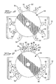
- the motor 114 is again operated to rotate its pulley 116 counterclockwise, as viewed in Figures 9 and 10, thereby rotating the right holder assembly 42 clockwise and the left holder assembly 44 counterclockwise, so that the two cutting and stripping blades 61 and 60' are further moved to engage and sever the insulation of the wire 12, and the two cutting and stripping blades 60 and 61' engage and sever the insulation of the new lead 14, as shown in Figures 10 and 11.
- the feed side transfer unit 20 retracts the wire 12
- the eject side transfer unit 26 retracts the end of the new lead 14 in the direction of the arrows 128 and 130, respectively, as shown in Figure 11.
- This movement of the feed and eject side ends serves to strip the severed slugs 132 of insulation from their ends, whereupon the slugs are picked by a suction in the tubes 124 and 126 and delivered to a scrap collection system for disposal.
- the motor 114 is then operated in the reverse direction to cause the pulley 116 to rotate clockwise, thereby rotating the right and left holder assemblies 42 and 44 counterclockwise and clockwise, respectively, until they reach the starting positions shown in Figure 2. The above process is then repeated any desired number of times.
- the right and left holder assemblies 42 and 44 are simply rotated in opposite directions by the motor 114 until the cutting and stripping blades 58 and 59 occupy the positions of the blades 60 and 61 and the blades 58' and 59' occupy the positions of the blades 60' and 61', shown in Figure 2.
- the above described operating process is then repeated using the 16 gage cutting and stripping blades 58, 59, 58', and 59'.
- the 20 gage cutting and stripping blades 62, 63, 62', and 63' are rotated to the present positions of the 18 gage cutting and stripping blades shown in Figure 2, and the above described operating process repeated.
- Such variations may include means for moving the severed ends of the wire 12 and new lead 14 in the directions of the arrows 128 and 130, respectively, as shown in Figure 11, other than the feed side and eject side transfer units 20 and 26. Additionally, other means may also be used to move the severed ends laterally into alignment with their respective spaces 120 and 122. Furthermore, assuming that the spaces 120 and 122 are large enough, the timing of the operations of the machine 10 may be controllable to allow the feeding of the ends of the wire 12 and the new lead 14 through their respective spaces 120 and 122 without momentarily stopping the rotation of the left and right holder assemblies 42 and 44.
- wire cutting and stripping unit 22 includes a belt driven mechanism powered by a rotary actuator to move the wire cutting and stripping blades, it will be understood that other actuating mechanisms may be advantageously utilized in the practice of the present invention.
- three sets of cutting and stripping blades are described for processing 16, 18, and 20 gage wire sizes, more or fewer such sets of blades may be accommodated on the left and right holder assemblies for processing any desired number of different wire sizes.
- An important advantage of the present invention is that the feed end and eject end of the severed wire can be positioned for any desired strip length, wherein the strip length is controllable through automation so that wires having different strip length requirements can be processed by the lead maker in succession without stopping the machine for adjustment.
- Another important advantage is that the cutting and stripping blade holders can accommodate several different sized sets of blades for cutting and stripping different gage wires which can be automatically positioned for use without stopping the machine.
- scrap collection tubes can be easily associated with the cutting and stripping blades to efficiently collect the scrap slugs of insulation that are stripped from the wire ends.
Landscapes
- Engineering & Computer Science (AREA)
- Manufacturing & Machinery (AREA)
- Mechanical Engineering (AREA)
- Removal Of Insulation Or Armoring From Wires Or Cables (AREA)
Applications Claiming Priority (2)
| Application Number | Priority Date | Filing Date | Title |
|---|---|---|---|
| US804785 | 1997-02-22 | ||
| US08/804,785 US5794494A (en) | 1997-02-22 | 1997-02-22 | Wire cutting and stripping mechanism |
Publications (2)
| Publication Number | Publication Date |
|---|---|
| EP0860912A2 true EP0860912A2 (fr) | 1998-08-26 |
| EP0860912A3 EP0860912A3 (fr) | 1999-09-22 |
Family
ID=25189831
Family Applications (1)
| Application Number | Title | Priority Date | Filing Date |
|---|---|---|---|
| EP98301272A Withdrawn EP0860912A3 (fr) | 1997-02-22 | 1998-02-20 | Mécanisme de coupage et de dénudage de fils |
Country Status (2)
| Country | Link |
|---|---|
| US (1) | US5794494A (fr) |
| EP (1) | EP0860912A3 (fr) |
Cited By (1)
| Publication number | Priority date | Publication date | Assignee | Title |
|---|---|---|---|---|
| CN103606796A (zh) * | 2013-09-25 | 2014-02-26 | 苏州晓炎自动化设备有限公司 | 一种全自动切线剥线机 |
Families Citing this family (4)
| Publication number | Priority date | Publication date | Assignee | Title |
|---|---|---|---|---|
| US6311600B1 (en) * | 1999-10-20 | 2001-11-06 | Hong Kong Polytechnic University | Electric power cable sheath cutter |
| CN102522676B (zh) * | 2011-12-20 | 2014-03-05 | 中山市亚泰机械实业有限公司 | 一种电脑裁剥线机 |
| CN106975930B (zh) * | 2017-03-29 | 2023-01-20 | 国网山东省电力公司菏泽供电公司 | 一种变压器台架生产线 |
| CN116594113B (zh) * | 2023-07-18 | 2023-09-19 | 国网吉林省电力有限公司信息通信公司 | 一种光缆安装工程的光缆绝缘层剥除装置 |
Family Cites Families (10)
| Publication number | Priority date | Publication date | Assignee | Title |
|---|---|---|---|---|
| US1802462A (en) * | 1927-10-31 | 1931-04-28 | Reserve Holding Co | Wire-skinning machine |
| US3027925A (en) * | 1957-11-22 | 1962-04-03 | Gronberg Anton Bertil | Rotary cutter having a vertically upward intake |
| US3831482A (en) * | 1969-03-10 | 1974-08-27 | Boehler & Co Ag Geb | Apparatus for cutting of fiber strands |
| US3973600A (en) * | 1975-01-06 | 1976-08-10 | Choromokos Robert L | Method and apparatus for feeding, cutting, stripping, coiling and tying off elongated flexible material |
| US4873901A (en) * | 1988-09-16 | 1989-10-17 | Artos Engineering Company | Apparatus for cutting and stripping insulation from wire segments having different gauge conductors |
| US5469763A (en) * | 1990-11-09 | 1995-11-28 | Eubanks Engineering Company | Wire and cable processing system |
| US5253555A (en) * | 1990-11-09 | 1993-10-19 | Eubanks Engineering Company | Multiple blade set strip apparatus for cable and wire |
| US5199328A (en) * | 1990-11-09 | 1993-04-06 | Eubanks Engineering Company | Multiple blade set strip apparatus for cable and wire |
| US5165319A (en) * | 1992-01-06 | 1992-11-24 | Advance Graphics Equipment Of York, Ltd. | Cutting knife with multiple insert blades |
| US5473811A (en) * | 1994-03-18 | 1995-12-12 | Atzet; Robert J. | Apparatus and method for striping insulated wire |
-
1997
- 1997-02-22 US US08/804,785 patent/US5794494A/en not_active Expired - Fee Related
-
1998
- 1998-02-20 EP EP98301272A patent/EP0860912A3/fr not_active Withdrawn
Cited By (1)
| Publication number | Priority date | Publication date | Assignee | Title |
|---|---|---|---|---|
| CN103606796A (zh) * | 2013-09-25 | 2014-02-26 | 苏州晓炎自动化设备有限公司 | 一种全自动切线剥线机 |
Also Published As
| Publication number | Publication date |
|---|---|
| EP0860912A3 (fr) | 1999-09-22 |
| US5794494A (en) | 1998-08-18 |
| MX9801368A (es) | 1998-08-30 |
Similar Documents
| Publication | Publication Date | Title |
|---|---|---|
| US5797299A (en) | Wire cutting and stripping mechanism | |
| US7178434B2 (en) | Orbiting blade coaxial cable cutter/stripper | |
| EP0989652B1 (fr) | Méthode et appareil de traitement d'une extrémité de câble | |
| CN114270644B (zh) | 用于剥离电缆的设备和方法、及用于制造电缆的系统 | |
| US11362492B2 (en) | Cable preparation machine having arcing contour blades | |
| EP3618207A1 (fr) | Mécanisme de torchage à tresse de câbles pour machine de préparation de câbles | |
| US11018483B2 (en) | Cable preparation machine | |
| WO2020049408A1 (fr) | Machine de dénudage par rotation et de préparation de câble | |
| JPH0591613A (ja) | ケーブル加工機械における電気ケーブルの切断及び剥離装置 | |
| CN111181090B (zh) | 快捷可适用不同粗细规格的电力电缆的剥皮装置 | |
| US5794494A (en) | Wire cutting and stripping mechanism | |
| JP2024070818A (ja) | 電線切断皮剥き装置、端処理電線製造装置、及び、端処理電線の製造方法 | |
| DE3686450T2 (de) | Vorrichtung zur herstellung von elektrischen kabelbaeumen. | |
| US3779290A (en) | Apparatus for untwisting and stripping twisted wire pair leads | |
| KR20170052503A (ko) | 케이블처리기용 절연피복 분리제거기 | |
| JPH06178421A (ja) | 被覆電線のストリップ製造方法 | |
| EP0050909B1 (fr) | Appareil à couper et à dénuder les fils | |
| CN110843000A (zh) | 纸管切割机 | |
| EP0728376B1 (fr) | Systeme de traitement de cables et de fils | |
| US4742613A (en) | Cable core self-aligning apparatus | |
| US4633919A (en) | Machine for cutting, bending and forming axial lead components | |
| WO1998012781A1 (fr) | Dispositif perfectionne conçu pour couper et denuder des fils | |
| JP2000175328A (ja) | 被覆電線の皮剥装置 | |
| MXPA98001368A (en) | Cutting and deflection mechanism of alam | |
| CN113753306A (zh) | 一种端子编带机 |
Legal Events
| Date | Code | Title | Description |
|---|---|---|---|
| PUAI | Public reference made under article 153(3) epc to a published international application that has entered the european phase |
Free format text: ORIGINAL CODE: 0009012 |
|
| AK | Designated contracting states |
Kind code of ref document: A2 Designated state(s): AT BE CH DE DK ES FI FR GB GR IE IT LI LU MC NL PT SE |
|
| AX | Request for extension of the european patent |
Free format text: AL;LT;LV;MK;RO;SI |
|
| PUAL | Search report despatched |
Free format text: ORIGINAL CODE: 0009013 |
|
| AK | Designated contracting states |
Kind code of ref document: A3 Designated state(s): AT BE CH DE DK ES FI FR GB GR IE IT LI LU MC NL PT SE |
|
| AX | Request for extension of the european patent |
Free format text: AL;LT;LV;MK;RO;SI |
|
| AKX | Designation fees paid | ||
| REG | Reference to a national code |
Ref country code: DE Ref legal event code: 8566 |
|
| STAA | Information on the status of an ep patent application or granted ep patent |
Free format text: STATUS: THE APPLICATION IS DEEMED TO BE WITHDRAWN |
|
| 18D | Application deemed to be withdrawn |
Effective date: 20000323 |