EP0860987A2 - Procédé et appareil pour l'analyse de diaposivites - Google Patents
Procédé et appareil pour l'analyse de diaposivites Download PDFInfo
- Publication number
- EP0860987A2 EP0860987A2 EP98102840A EP98102840A EP0860987A2 EP 0860987 A2 EP0860987 A2 EP 0860987A2 EP 98102840 A EP98102840 A EP 98102840A EP 98102840 A EP98102840 A EP 98102840A EP 0860987 A2 EP0860987 A2 EP 0860987A2
- Authority
- EP
- European Patent Office
- Prior art keywords
- slide
- values
- pixel elements
- ccd sensor
- pixel
- Prior art date
- Legal status (The legal status is an assumption and is not a legal conclusion. Google has not performed a legal analysis and makes no representation as to the accuracy of the status listed.)
- Withdrawn
Links
Images


Classifications
-
- H—ELECTRICITY
- H04—ELECTRIC COMMUNICATION TECHNIQUE
- H04N—PICTORIAL COMMUNICATION, e.g. TELEVISION
- H04N1/00—Scanning, transmission or reproduction of documents or the like, e.g. facsimile transmission; Details thereof
- H04N1/40—Picture signal circuits
- H04N1/401—Compensating positionally unequal response of the pick-up or reproducing head
Definitions
- the invention relates to a method and an apparatus for scanning in slides, comprising a commercially available slide projector and an auxiliary device, insertable into an opening for a projector lens, having an imaging lens and a CCD sensor.
- An accessory device for a slide projector is known from German Utility Model U1-296 09 621.
- the accessory device can be inserted into a slide projector in place of the interchangeable lens.
- An electronic image sensing device (CCD) by means of which the recorded images can be transferred to a TV unit and/or to a video recorder, is provided in the accessory device.
- a wide-angle projection lens images a corresponding slide onto a matte screen, ensuring homogeneous illumination.
- a camera lens placed in front of the image sensing device images the matte screen onto the image sensing device.
- Document DE-A-36 09 931 discloses a slide projection device in which the slide is exposed directly onto a video tube device.
- the video tube is arranged in the lens housing of a conventional slide projector, and possesses a device for transferring the electrical output of the video tube device to a video display.
- the apparatus also possesses a device for the direct projection of color negatives.
- the device comprises a filter and a means for reversing the color and saturation output signals of the video tube device.
- Document DE-A-32 15 713 describes an apparatus for scanning an image, located on a slide, using a television camera.
- the slide is projected directly onto the sensing tube of the television camera in order to eliminate the disadvantages of imaging the slide onto a matte screen.
- disadvantages in the use of a matte screen are the fact that an additional unit is necessary, and further that the quality of the images sensed by the television camera and reproduced on the monitor is impaired by dust or minor defects on the matte screen.
- the light output of the lamp is reduced by at least 50 % so that the sensing tube of the television camera is not endangered by the high light output of the lamp.
- a further object of the invention is to create an apparatus with which slides can be easily and economically scanned in and electronically modified or corrected in terms of the illumination properties of the projection lamp, in order to obtain an artifact-free reproduction of the scanned-in slide.
- the advantage of the method is that commercially available slide projectors can be used for the slide scanner, and that the use of a matte screen can be dispensed with.
- the slides are imaged directly onto the CCD sensor.
- Homogeneous illumination of the slide, as is attained with the matte screen, is achieved by electronic methods, by correlating the image data of the sensed slide with the image data of a reference slide.
- the advantage of the apparatus is that a commercially available slide projector can be used for scanning in and archiving.
- the auxiliary device required for scanning, with imaging lens and CCD sensor, must simply be inserted into the opening for the projection lens of the slide projector, so that no modifications to the slide projector itself are required.
- the slide, illuminated by the lamp of the slide projector, is imaged directly onto the CCD sensor.
- a matte screen, required to achieve homogeneous illumination, is not provided. This eliminates any impairment in quality due to the grain of the matte screen.
- Fig. 1 shows a slide projector 2 with an auxiliary device 24 according to the prior art, for scanning in one or more slides, inserted into the slide projector 2.
- An optical system 4 provided in slide projector 2, for example reflector 10, lamp 12, condenser 14, and optical filter 16, is used to illuminate a slide 6 that is to be imaged.
- Auxiliary device 24 - which is made up of a first imaging lens 26 or a first imaging system 26, a matte screen 27, and a second imaging lens 28 or a second imaging system 28 and a CCD sensor 8 - is inserted into an opening 22 for a projection lens (not shown). Matte screen 27 is configured in terms of its diffusion properties in such a way that imaging of the image created on matte screen 27 is possible.
- First imaging lens 26 (or the first optical system) forms the image of slide 6 on the matte screen 27.
- Second imaging lens 28 (or the second optical system) forms the image of slide 6 on the matte screen on CCD sensor 8.
- the result of the intermediate image on the matte screen 27 is that all the light rays from all directions contribute to an intermediate image. This allows uniformly good illumination of the CCD sensor 8 in the imaging plane.
- Fig. 2 schematically depicts the apparatus according to the invention. Elements or components already known from the prior art (see Fig. 1) are designated with the same reference numerals.
- a commercially available slide projector 2 is once again used for the apparatus for scanning in slides.
- the optical system 4 of slide projector 2 consists substantially of the components disclosed in Fig. 1.
- An auxiliary device 24' which comprises a CCD sensor 8' and an imaging lens 28' placed in front of it, is inserted into opening 22 for the projection lens.
- Slide 6 illuminated by lamp 12 of slide projector 2, is imaged directly onto the CCD sensor 8' by means of imaging lens 28'. Charges are generated in the individual pixels of CCD sensor 8' in accordance with the image on the slide 6.
- the values corresponding to the charges in the individual pixels of the CCD sensor 8' are sent via a corresponding data line 30 to a computer 32.
- a software program which corrects the individual pixel of the slide 6 in accordance with the data of a reference slide is implemented in the computer 32.
- the data for the individual pixel of the reference slide are stored in the memory of the computer 32, and can be retrieved therefrom as needed. It is self-evident that different formats of reference slides are available for the different slide formats.
- the reference slides and the corresponding program are required in order to eliminate the design-related artifacts which are imaged, with varying degrees of sharpness, by the imaging lens 28' or the imaging lens system 14, and also by the lamp 12 and the mirror 10.
- the result is artifacts in the form of brighter or darker areas in the image projected onto the CCD sensor 8'.
- the prior art uses a matte screen 27 to eliminate these artifacts to the greatest extent possible.
- a reference slide together with a suitable software program is used for the purpose. Matte screen 27 of the prior art is thus no longer needed.
- the format of the reference slides is, in this context, dimensioned so that it can cover both horizontal-format and a vertical-format slides.
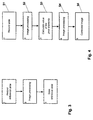
- the method for determining the data of a reference slide is depicted in Fig. 3.
- the corresponding reference slide is transilluminated using the apparatus disclosed in Fig. 2, and the image of said reference slide is imaged directly onto the CCD sensor 8'.
- the values of the individual pixels of the CCD sensor 8' are read out, and transferred to a computer 32.
- Processing of the image data of the reference slide is performed by means of a software program.
- the image data of the reference slide can be, for example, smoothed, filtered, or converted into a neutral density.
- the algorithms used to process the image data do not need to be discussed in further detail here, since they are state of the prior art.
- the data obtained for the individual pixels after image processing of the image data of the reference slide are stored in a memory provided for the purpose.
- the memory can be the hard drive, a floppy disk, or the RAM of the image-processing computer 32.
- the corrected or processed data of the reference slide are stored in the memory of the computer, and can be retrieved from memory at any time for correction of the slide imaged on CCD sensor 8' (see Fig. 4).
- the values of the individual pixels of the CCD sensor 8' are read out, and the image of the slide just recorded is displayed on the monitor of computer 32 (step S1, imaging). At this stage, no modifications or corrections of any kind have been made to the image data.
- filtering or edge improvement operations or the like can be performed on the image data of the recorded slide comprising the individual pixels.
- a next step S3 the stored image data of the reference slide are retrieved from the memory and correlated with the image data of the recorded and already processed slide, in such a way that the aforementioned artifacts disappear.
- the mutually corresponding pixels of the recorded slides are respectively divided by the pixels of the reference slide.
- a further possibility would be to multiply the mutually corresponding pixels of the recorded slide respectively by the reciprocal values of the pixels of the reference slide.
- Calculation of the image data of the slide can be followed by a further step S4 in which further filtering, edge improvement, etc. operations are additionally performed.
- step S5 a calculated image is available that is free of artifacts and can be made available to the user in any fashion, for example by display on the monitor (not shown), a printout, or storage.
Landscapes
- Engineering & Computer Science (AREA)
- Multimedia (AREA)
- Signal Processing (AREA)
- Facsimile Scanning Arrangements (AREA)
- Image Input (AREA)
- Storing Facsimile Image Data (AREA)
- Facsimile Image Signal Circuits (AREA)
- Apparatus For Radiation Diagnosis (AREA)
- Transforming Electric Information Into Light Information (AREA)
Applications Claiming Priority (2)
| Application Number | Priority Date | Filing Date | Title |
|---|---|---|---|
| DE19707161 | 1997-02-22 | ||
| DE1997107161 DE19707161A1 (de) | 1997-02-22 | 1997-02-22 | Verfahren und Vorrichtung zum Einscannen von Dias |
Publications (2)
| Publication Number | Publication Date |
|---|---|
| EP0860987A2 true EP0860987A2 (fr) | 1998-08-26 |
| EP0860987A3 EP0860987A3 (fr) | 1998-11-11 |
Family
ID=7821202
Family Applications (1)
| Application Number | Title | Priority Date | Filing Date |
|---|---|---|---|
| EP98102840A Withdrawn EP0860987A3 (fr) | 1997-02-22 | 1998-02-19 | Procédé et appareil pour l'analyse de diaposivites |
Country Status (3)
| Country | Link |
|---|---|
| EP (1) | EP0860987A3 (fr) |
| JP (1) | JPH10243189A (fr) |
| DE (1) | DE19707161A1 (fr) |
Families Citing this family (1)
| Publication number | Priority date | Publication date | Assignee | Title |
|---|---|---|---|---|
| DE10309325A1 (de) * | 2003-03-04 | 2004-09-16 | Bts Media Solutions Gmbh | Einrichtung zur Kompensation von Fluktuationen einer Lichtquelle und Filmabtaster |
Family Cites Families (6)
| Publication number | Priority date | Publication date | Assignee | Title |
|---|---|---|---|---|
| US3800079A (en) * | 1972-12-18 | 1974-03-26 | Ibm | Compensation for a scanning system |
| FR2487613A1 (fr) * | 1980-07-24 | 1982-01-29 | Matra | Dispositif de lecture ou de restitution d'un document, en particulier pour appareil de telecopie |
| DE3215713C2 (de) * | 1982-04-28 | 1986-03-06 | Fa. Ed. Liesegang, 4000 Düsseldorf | Einrichtung zum Abtasten einer auf einem unbeweglichen Film befindlichen Abbildung mit einer Fernsehkamera |
| EP0606128B1 (fr) * | 1986-11-14 | 1999-02-17 | Canon Kabushiki Kaisha | Appareil de traitement d'images en couleurs |
| US5412489A (en) * | 1991-06-29 | 1995-05-02 | Minolta Camera Kabushiki Kaisha | Shading correction having a line memory read which generates an average reference level from a plurality of lines of a reference plate |
| US5361140A (en) * | 1992-02-18 | 1994-11-01 | Neopath, Inc. | Method and apparatus for dynamic correction of microscopic image signals |
-
1997
- 1997-02-22 DE DE1997107161 patent/DE19707161A1/de not_active Withdrawn
-
1998
- 1998-02-18 JP JP10035744A patent/JPH10243189A/ja active Pending
- 1998-02-19 EP EP98102840A patent/EP0860987A3/fr not_active Withdrawn
Also Published As
| Publication number | Publication date |
|---|---|
| JPH10243189A (ja) | 1998-09-11 |
| DE19707161A1 (de) | 1998-08-27 |
| EP0860987A3 (fr) | 1998-11-11 |
Similar Documents
| Publication | Publication Date | Title |
|---|---|---|
| US7245325B2 (en) | Photographing device with light quantity adjustment | |
| US7433089B2 (en) | Image processor | |
| US7057645B1 (en) | Camera system that compensates low luminance by composing multiple object images | |
| US7590335B2 (en) | Digital camera, composition correction device, and composition correction method | |
| US7202888B2 (en) | Electronic imaging device resolution enhancement | |
| US6995793B1 (en) | Video tap for a digital motion camera that simulates the look of post processing | |
| JP3436688B2 (ja) | 画像再生装置 | |
| EP0851675A2 (fr) | Méthode et dispositif pour la détermination automatique de l'orientation d'une caméra numérique | |
| JP2889860B2 (ja) | 色分解走査装置の作動における画像の嵌込みを行う方法 | |
| JPH07288826A (ja) | フィルム画像再生装置 | |
| JP2001119707A (ja) | アンチエイリアジング機能を備えたカラー画像撮像システム | |
| JP2003348422A (ja) | 撮像装置及び撮像方法及びプログラム及び記憶媒体 | |
| JP3783817B2 (ja) | 画像処理方法および画像処理装置 | |
| JP3549413B2 (ja) | 画像処理方法および画像処理装置 | |
| US6907145B2 (en) | Image processing apparatus, certification photograph taking apparatus, and certification photograph creation system | |
| JP2002157588A (ja) | 画像データ処理方法及び装置と該方法を実行するためのプログラムを記録した記録媒体 | |
| JP4489274B2 (ja) | ディジタル・カメラおよびその制御方法ならびに画像出力装置および方法 | |
| JPH11224324A (ja) | 画像信号処理方法及び装置 | |
| JPH09307676A (ja) | 画像読取装置 | |
| JP2002305676A (ja) | 電子カメラ | |
| EP0901280A2 (fr) | Dispositif et méthode pour photographie numérique | |
| JPH10243189A (ja) | スライド走査方法 | |
| JPH10210287A (ja) | デジタルカメラ | |
| JPS62203477A (ja) | 画像読取装置 | |
| JP4019660B2 (ja) | 画像データ処理装置、画像データ処理方法、及び、プログラム |
Legal Events
| Date | Code | Title | Description |
|---|---|---|---|
| PUAI | Public reference made under article 153(3) epc to a published international application that has entered the european phase |
Free format text: ORIGINAL CODE: 0009012 |
|
| AK | Designated contracting states |
Kind code of ref document: A2 Designated state(s): DE FR GB IT NL SE |
|
| PUAL | Search report despatched |
Free format text: ORIGINAL CODE: 0009013 |
|
| AK | Designated contracting states |
Kind code of ref document: A3 Designated state(s): AT BE CH DE DK ES FI FR GB GR IE IT LI LU MC NL PT SE |
|
| 17P | Request for examination filed |
Effective date: 19990506 |
|
| AKX | Designation fees paid |
Free format text: DE FR GB IT NL SE |
|
| 17Q | First examination report despatched |
Effective date: 20020524 |
|
| STAA | Information on the status of an ep patent application or granted ep patent |
Free format text: STATUS: THE APPLICATION IS DEEMED TO BE WITHDRAWN |
|
| 18D | Application deemed to be withdrawn |
Effective date: 20021004 |