EP0861569B1 - Douille de connexion pour terminaux de telecommunication - Google Patents
Douille de connexion pour terminaux de telecommunication Download PDFInfo
- Publication number
- EP0861569B1 EP0861569B1 EP96934297A EP96934297A EP0861569B1 EP 0861569 B1 EP0861569 B1 EP 0861569B1 EP 96934297 A EP96934297 A EP 96934297A EP 96934297 A EP96934297 A EP 96934297A EP 0861569 B1 EP0861569 B1 EP 0861569B1
- Authority
- EP
- European Patent Office
- Prior art keywords
- socket
- interface
- connection
- supply
- terminal equipment
- Prior art date
- Legal status (The legal status is an assumption and is not a legal conclusion. Google has not performed a legal analysis and makes no representation as to the accuracy of the status listed.)
- Expired - Lifetime
Links
- 239000008186 active pharmaceutical agent Substances 0.000 claims description 6
- 230000005540 biological transmission Effects 0.000 description 6
- 230000006870 function Effects 0.000 description 3
- 239000011505 plaster Substances 0.000 description 3
- 238000005265 energy consumption Methods 0.000 description 2
- 230000010354 integration Effects 0.000 description 2
- JBFLYOLJRKJYNV-MASIZSFYSA-N (1z)-1-[(3,4-diethoxyphenyl)methylidene]-6,7-diethoxy-3,4-dihydro-2h-isoquinoline;hydron;chloride Chemical compound Cl.C1=C(OCC)C(OCC)=CC=C1\C=C/1C2=CC(OCC)=C(OCC)C=C2CCN\1 JBFLYOLJRKJYNV-MASIZSFYSA-N 0.000 description 1
- 230000000295 complement effect Effects 0.000 description 1
- 238000001816 cooling Methods 0.000 description 1
- 238000001914 filtration Methods 0.000 description 1
- 230000011664 signaling Effects 0.000 description 1
Images


Classifications
-
- H—ELECTRICITY
- H04—ELECTRIC COMMUNICATION TECHNIQUE
- H04M—TELEPHONIC COMMUNICATION
- H04M1/00—Substation equipment, e.g. for use by subscribers
- H04M1/02—Constructional features of telephone sets
- H04M1/0293—Terminal boxes for telephone sets
-
- H—ELECTRICITY
- H04—ELECTRIC COMMUNICATION TECHNIQUE
- H04M—TELEPHONIC COMMUNICATION
- H04M1/00—Substation equipment, e.g. for use by subscribers
- H04M1/71—Substation extension arrangements
- H04M1/715—Substation extension arrangements using two or more extensions per line
-
- H—ELECTRICITY
- H04—ELECTRIC COMMUNICATION TECHNIQUE
- H04Q—SELECTING
- H04Q11/00—Selecting arrangements for multiplex systems
- H04Q11/04—Selecting arrangements for multiplex systems for time-division multiplexing
- H04Q11/0428—Integrated services digital network, i.e. systems for transmission of different types of digitised signals, e.g. speech, data, telecentral, television signals
- H04Q11/0435—Details
- H04Q11/0471—Terminal access circuits
Definitions
- the present invention relates to a connection socket for telecommunications terminals according to the subject of claims 1 and 2.
- the digitization of a subscriber line is the main technical innovation at one Telecommunication network based on ISDN (Integrated Services Digital Network) standards compared to a digital telecommunications network with transmission of analog signals to user stations.
- ISDN Integrated Services Digital Network
- Under a user station becomes a unit that can be connected to a switching unit via a connecting line understood, which consist of a network termination unit and one or more terminal devices exists, the terminals either being of the same type, e.g. multiple telephones, or different are, e.g. Voice and text devices.
- Further details on user stations are, for example Peter Bocker, ISDN - The integrated service digital news network (2nd edition, Berlin, 1990), pages 59 ff.
- the network termination unit provides the connection of the user station to the connection line and enables the shared use of the connecting line by several end devices.
- Network Termination Units are currently in separate device units for mounting on a wall or as table-top device units available and take up space on the one hand and on the other hand require a separate connection option and cabling to the connection line and to the end devices.
- Such Network termination units are for example from European patent publication EP 0668706 A2 and U.S. Patent No. 5,243,642.
- the present invention is therefore based on the object of specifying a network termination in which fewer device components are required and the wiring is considerably simplified.
- connection socket of the type mentioned at the outset solved in two ways.
- a solution is provided by the subject matter of patent claim 1 given measures given. Accordingly, an alternative solution is through the item of claim 2 specified features realized.
- the invention has the following advantages: Through the complete integration of the network termination unit in one Socket simplifies wiring and reduces the number of sockets required. The operational safety of user stations can be improved, in particular, by the simple wiring be significantly increased. In addition, there is no additional space for a free-standing Network termination unit required.
- Fig. 1 is a user station consisting of eight sockets D1 to D8 and eight terminals E1 to E8 shown, via a connection line ASL to a switching unit according to ISDN standards built Listeldenetzes ISDN is connected, it being the sockets D1 to D8 can be so-called surface-mounted or flush-mounted sockets, preferably in one cylindrical cavity with an inner diameter of approx. 65 mm and a cylinder height of approx. 53 mm are embedded.
- the sockets D1 to D8 are via a multi-core connecting line VU connected to each other, this connecting line VU is preferably arranged under plaster.
- Terminals E1 to E8 are connected to terminals A1 to A8 via connecting lines V1 to V8 Sockets D1 to D8 can be connected, the connecting lines V1 to V8 preferably using plaster are arranged.
- a feed unit SP is provided, which also has a feed line VS a supply connection SPA of the socket D1 is connected.
- a basic connection consists of two so-called B channels for the transmission of user data at a transmission rate of 64 kbit / s each and a so-called D channel for the transmission of signaling data with a transmission rate of 16 kbit / s.
- the network termination unit contained in the user station has a U interface to the ISDN network US and an S interface SS to the terminals E1 to E8.
- the network termination unit is via the Connection line ASL is supplied with energy by the switching unit of the ISDN network.
- the local supply voltage fails - one of the Eight terminals E1 to E8 are supplied with energy via the switching unit of the ISDN network. This condition is called emergency operation.
- the network termination unit has a Protection circuit to block overvoltages, a hybrid circuit to separate between incoming and outgoing signal and an echo cancellation unit, with whose help crosstalk and echo signal components are eliminated.
- the corresponding circuit parts of the network termination unit are fully integrated according to the invention in the socket D1.
- the S interface SS represents the subscriber-side termination of the network termination unit.
- up to eight terminals E1 to E8 can be connected to the network termination unit, with a maximum of two of these eight terminals E1 to E8 maintaining a connection to the switching unit of the ISDN telecommunications network at the same time can.
- the connections VU and V1 to V8 from the network termination unit to the terminals E1 to E8 are often also referred to as S-Bus, the S-Bus also including the feed lines mentioned in addition to the switching lines.
- the S-bus please refer to the ISDN standard ITU-T 1.430, with regard to the basic connection to the ISDN standard ITU-G.961 and with regard to the network termination unit to the ISDN standard ETR 080.
- the network termination unit is integrated in the socket D1. Because of the limited space - especially if the socket is inserted into a cylindrical cavity with an inner diameter of approx. 65 mm and a cylinder height of approx. 53 mm - it is not possible to integrate all circuit parts into socket D1. For this reason, in the embodiment of the invention shown in FIG. 1, a first part of the network termination unit is contained in the socket D1 and a second part of the network termination unit is arranged outside the socket D1. While the circuit parts of the network termination unit for the U interface US and for the S interface SS are completely integrated in the socket D1, the supply for the terminals E1 to E8 is outsourced to the supply unit SP.
- the division of the network termination unit into a first and a second part has the advantage that the operational reliability of the network termination unit is increased overall by separating the supply from the other circuit elements, since interference from switching parts of the supply (220 V) to circuit parts of the network termination unit (5 up to 40 V) can be avoided.
- special precautions for cooling circuit components are largely omitted if, when dividing the network termination unit, care is taken that modules with relatively low energy consumption are plugged into socket D1 and modules with higher energy consumption, such as the supply, are arranged outside socket D1 are.
- the division of the network termination unit into two parts has the result that - if, as shown in FIG. 1, A terminal should also be connectable to the socket D1 - in addition to the terminal connection A1 a supply connection SPA is also provided, to which the supply unit SP is connected via a supply line VS can be connected.
- a feed line is also conceivable that plastered directly to the Network termination unit can be connected, with which the socket D1 - like the other sockets D2 to D8 - has no SPA supply connection.
- the supply unit SP is preferably a plug-in power supply unit with a connector plug integrated into the housing, which can be connected to the energy supply system, as a result of which the supply unit SP is spatially fixed. Only the supply line VS is still on via the supply connection SPA to connect the socket D1.
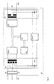
- FIG. 2 shows a network termination device known from EP 0 668706 A2, which according to the invention is incorporated in FIG Socket D1 was integrated.
- This network termination device contains two separate bus systems IOM2 (2B + D-channel bus) and PB (processor bus), allows the optional connection of two analog terminals E21, E22 and up to six digital terminals E11, ..., E16 via a U interface US with a switching unit of the ISDN.
- the first bus system IOM2 connects one with the U interface US connected echo compensation module IEC with a communication controller ICC and with an S interface module SBCX and two ab interface modules LIF1a or LIF2a.
- the S interface module SBCX is connected to the digital end devices via an S interface SS E11, ..., E16 and the ab interface modules LIF1a and LIF2a are via ab interfaces ab1; ab2 each connected to an analog terminal E21 or E22.
- the terminal E22 is in the present Case a fax machine.
- the second bus system PB connects the communication control ICC and the ab interface modules LIF1a or LIF2a with a processor system PCS, which by a Processor MC, a memory module MEM and an oscillator OSZ is formed.
- a Power-up controller PUC provided that via a feed line VS, a supply connection SPA and a module VFF, which is preferably provided for protection, filtering and power distribution a supply voltage output by an external supply unit SP is supplied.
- the Power-up controller PUC signals the status of the supply voltage to the processor MC, the necessary switch-on and switch-off (power-up, power-down) routines are carried out in good time can be.
- the necessary switch-on and switch-off (power-up, power-down) routines are carried out in good time can be.
- the local power supply fails, it is often necessary that the power consumption of the circuit arrangement is greatly reduced, since in this case the supply done by the switching unit. It is provided that only one of the (analog or digital) terminals E11, ..., E22 is put into operation.
- connection A11 is preferred for a digital and a connection A12 is intended for an analog terminal device E11 or E21.
- a disadvantage with the arrangement described in FIG. 2 remains the need to use a external supply device SP, not least because of security reasons not in the socket D1 can be integrated.
- the connected Terminals E and the modules provided in socket D1 can only be used by the Switch unit to supply operating voltage supplied.
- the prerequisite for this is that the participant claimed power does not exceed the value specified by the ISDN network operator. In this case, so that all the intended terminals E with all their functions are available the polarity of the voltage applied to the S interface SS was not changed.
- the feeding of the Network termination and the terminals E is therefore carried out in full by the switching unit supplied supply voltage.
- FIG. 6 shows the socket D1 with the network termination device integrated therein, this as well as the terminals E connected to the S interface from the switching unit of the ISDN is fed via the U interface US. From the input transformer IT supplied DC voltage is removed and fed to a DC / DC converter, which the required supply voltages are generated, one of which without changing the polarity of the S interface SS is fed.
- the subscriber should be able to connect a supply device SP to the integrated network termination device (see Figs. 1-4).
- the SPA supply connection is provided for this purpose.
- the power supply takes place below the value specified by the ISDN network operator in the event of a failure of the local power supply, preferably as described above, via the U interface US without changing polarity.
- the participant is available during normal and emergency operation all terminals E are available without restriction. A burden on the communication network In this case, however, it only occurs during a local power failure.
- the operating mode of the network termination device therefore depends on whether a local power supply is provided and whether the power requirement of the connected terminals equals the value of the communication network provided performance exceeds. There is therefore a (direct or indirectly) to provide manually operated switch DS, through which the operating mode (with or without Polarity change during emergency operation) is adjustable.
- the supply connection is preferably SPA with a switch DS (see Fig. 3) provided when inserting the plug of the power supply SP is operated. If no local power supply is provided and therefore no plug inserted the power supply takes place completely and without polarity change via the U interface US (analogous to the circuit arrangement according to FIG. 6). If a local power supply is provided, If they fail, the power supply is carried out via the U interface US with polarity change. On Polarity changes can be avoided when using devices with low power requirements if the switch DS is set manually (not indirectly through the plug) in such a way that there is no change of polarity if the local power supply fails.
- FIG. 3 An example of an embodiment of this preferred embodiment of the invention is shown in FIG. 3.
- the data transmission from and to the terminals takes place in a known manner via a first one IT transformer, the echo compensation module IEC, the S-interface module SBCX and one second transformer SF.
- the supply voltage supplied by the switching unit is from the first transformer IT via a DC / DC converter, a controllable switch US, a controllable polarity converter INV and can be transferred to the four-wire S-bus via the second transformer SF.
- the switch US can also supply the supply voltage of the local supply device SP.
- a line vd the status of the local supply voltage and the presence of the switch DS a plug in the supply connection SPA or the intended emergency operation (polarity change: yes / no) reported.
- the PUC power-up controller if available, therefore local and otherwise the supply voltage supplied by the switching unit for feeding the network termination device and the terminals E switched through.
- the control line is for emergency operation if necessary, a change in polarity of the supply voltage applied to the S-Bus is initiated.
- the switch US and the polarity converter INV can also by a switch module IUS can be realized, as shown in Fig. 4.
- PUC-connected switchover module IUS can either supply voltage via contacts K1, ..., K6 from the supply device SP or the voltage delivered by the DC / DC converter with or without changing the polarity of the S interface SS.
- the blocks PEB is preferred 3023 or PEB 4065 from Siemens, which is a space-saving electronic hybrid contain.
- This socket D1 has a housing cup GB with two guide rails FS in which two e.g. connected to each other via a plug connection or a flat cable CONN Circuit boards A-PCB and NT-PCB can be inserted.
- the first circuit board A-PCB carries the connection components (Transformers, sockets, etc.).
- the second circuit board NT-PCB carries the components of the Power termination device and the DC / DC converter.
- the circuit boards A-PCB and NT-PCB are arranged in such a way that their components are aligned opposite each other.
- a recess SR is preferred for flush-mounted boxes cylindrical housing cup GB provided.
- Fasteners and covers are also included provided, which allow the connection socket to be mounted on or under plaster.
Landscapes
- Engineering & Computer Science (AREA)
- Signal Processing (AREA)
- Computer Networks & Wireless Communication (AREA)
- Telephonic Communication Services (AREA)
- Details Of Connecting Devices For Male And Female Coupling (AREA)
- Structure Of Telephone Exchanges (AREA)
Claims (12)
- Prise (D1) de connexion pour terminaux de télécommunication comportant au moins une borne (A1 ou A11, A12, A13) de terminal pour la connexion d'un terminal (E1 ou E11, E21, E22), la prise (D1) de connexion contenant une unité de terminaison sur réseau qui peut être raccordée par l'intermédiaire d'une première interface à un réseau (ISDN) de télécommunication numérique et qui comporte une interface (SS) S qui est reliée à au moins une borne (A11) de terminal et qui peut être reliée par l'intermédiaire d'une ligne (VU) de liaison à des terminaux (E2 à E8) supplémentaires.
- Prise (D1) de connexion pour terminaux de télécommunication comportant au moins une borne (A1 ou A11, A12, A13) de terminal pour la connexion d'un terminal (E1 ou E11, E21, E22), la prise (D1) de connexion contenant une unité de terminaison sur réseau qui peut être raccordée par l'intermédiaire d'une première interface (US) à un réseau (ISDN) de télécommunication numérique et qui comporte au moins une interface (ab1, ab2) ab reliée à une borne (A12, A13) de terminal et une interface (SS) S qui est reliée à au moins une borne (A11) de terminal et qui peut être reliée par l'intermédiaire d'une ligne (VU) de liaison à des terminaux (E2 à E8) supplémentaires.
- Prise (D1) de connexion suivant la revendication 1 ou 2, caractérisée en ce que la prise (D1) de connexion comporte une borne (SPA) d'alimentation pour la connexion d'une unité (SP) d'alimentation ou en ce que l'appareil de terminaison sur réseau ne peut être alimenté qu'exclusivement par l'intermédiaire de l'interface (US) U sans qu'il s'effectue une inversion de polarité de la tension appliquée à l'interface (SS) S.
- Prise (D1) de connexion suivant la revendication 1 ou 2, caractérisée en ce que la prise (D1) de connexion comporte une borne (SPA) d'alimentation pour la connexion d'une unité (SP) d'alimentation et en ce qu'il est prévu un Power-up-Controller (PUC) qui commande un commutateur (US ; IUS) de telle manière que, en cas de panne locale du courant, l'alimentation en courant s'effectue par l'intermédiaire de l'interface (US) U.
- Prise (D1) de connexion suivant la revendication 4, caractérisée en ce qu'il est prévu un commutateur (DS) par lequel il peut être réglé, pour le fonctionnement en détresse, une inversion de polarité de la tension envoyée au bus (S) par l'intermédiaire de l'interface (US) U.
- Prise (D1) de connexion suivant la revendication 5, caractérisée en ce que le commutateur (DS) est relié mécaniquement à la borne (SPA) en alimentation et peut être actionné par le connecteur de l'unité (SP) d'alimentation, si bien que l'alimentation de l'interface (SS) S s'effectue sans inversion de polarité par l'intermédiaire de l'interface (US) U lorsque le connecteur n'est pas inséré et avec inversion de polarité par l'intermédiaire de l'interface (US) U lorsque le connecteur est inséré et en cas de panne locale du courant.
- Prise (D1) de connexion suivant l'une des revendications 1 à 6, caractérisée en ce qu'il est prévu un boítier (GB) dans lequel peuvent être insérées deux platines (A-PCB, NT-PCB) à circuit imprimé qui sont reliées l'une à l'autre, dont la première porte les composants nécessaires à la connexion des terminaux (E11, ..., E16 ; E21, E22) et dont la seconde porte les composants de l'appareil de terminaison sur réseau, les composants étant disposés de manière qu'il ne soit pas prévu de composants entre les platines (A-PCB, NT-PCB) à circuit imprimé ou de façon qu'il n'y soit prévu que des composants SMD.
- Prise (D1) de connexion suivant la revendication 7, caractérisée en ce qu'il est prévu des dimensions qui permettent à un montage dans une cavité en forme de cylindre ayant un diamètre intérieur d'environ 65 mm et une hauteur de cylindre d'environ 53 mm.
- Prise (D1) de connexion suivant la revendication 7 ou 8, caractérisée en ce que le boítier (GB) comporte un évidement (SR) pour abriter les câbles (VU, ASL) de connexion.
- Prise (D1) de connexion suivant l'une des revendications 7 à 9, caractérisée en ce que la deuxième platine (NT-PCB) à circuit imprimé porte de plus un convertisseur (DC/DC) de tension continue servant à produire les tensions d'alimentation nécessaires.
- Prise (D1) de connexion suivant l'une des revendications 1 à 10, caractérisée en ce que l'appareil de terminaison sur réseau est raccordé côté abonné par des termineurs électroniques aux interfaces (ab, SS) analogiques et/ou numériques.
- Prise (D1) de connexion suivant l'une des revendications 1 à 11, caractérisée en ce qu'il est prévu des moyens de fixation et des recouvrements qui permettent un montage de la prise (D1) de connexion sur crépi ou de manière encastrée.
Applications Claiming Priority (4)
| Application Number | Priority Date | Filing Date | Title |
|---|---|---|---|
| CH323895 | 1995-11-15 | ||
| CH3238/95 | 1995-11-15 | ||
| CH323895 | 1995-11-15 | ||
| PCT/CH1996/000385 WO1997018686A1 (fr) | 1995-11-15 | 1996-11-01 | Douille de connexion pour terminaux de telecommunication |
Publications (2)
| Publication Number | Publication Date |
|---|---|
| EP0861569A1 EP0861569A1 (fr) | 1998-09-02 |
| EP0861569B1 true EP0861569B1 (fr) | 2002-04-10 |
Family
ID=4251649
Family Applications (1)
| Application Number | Title | Priority Date | Filing Date |
|---|---|---|---|
| EP96934297A Expired - Lifetime EP0861569B1 (fr) | 1995-11-15 | 1996-11-01 | Douille de connexion pour terminaux de telecommunication |
Country Status (9)
| Country | Link |
|---|---|
| EP (1) | EP0861569B1 (fr) |
| AR (1) | AR004565A1 (fr) |
| AT (1) | ATE216175T1 (fr) |
| DE (2) | DE59609072D1 (fr) |
| ES (1) | ES2171724T3 (fr) |
| NO (1) | NO982163L (fr) |
| PT (1) | PT861569E (fr) |
| WO (1) | WO1997018686A1 (fr) |
| ZA (1) | ZA969488B (fr) |
Families Citing this family (1)
| Publication number | Priority date | Publication date | Assignee | Title |
|---|---|---|---|---|
| DE10002958A1 (de) * | 2000-01-25 | 2001-07-26 | Philips Corp Intellectual Pty | Telefonanschlussdose |
Family Cites Families (7)
| Publication number | Priority date | Publication date | Assignee | Title |
|---|---|---|---|---|
| DE3839266A1 (de) * | 1988-11-21 | 1990-05-23 | Rose Walter Gmbh & Co Kg | Vorrichtung zur bildung einer uebergabestelle in einem fernmeldenetz |
| JPH02192397A (ja) * | 1989-01-20 | 1990-07-30 | Nec Corp | Isdn網終端装置 |
| CH678135A5 (fr) * | 1989-05-24 | 1991-07-31 | Kapsch Ag | |
| US5243642A (en) * | 1991-07-12 | 1993-09-07 | Bell Atlantic Network Services, Inc. | Telephone call management device |
| DE4132917C2 (de) * | 1991-10-04 | 1994-02-10 | Gaertner Karl Telegaertner | Telefonvermittlungsanlage |
| DK0668706T3 (da) * | 1994-01-27 | 1999-11-01 | Siemens Schweiz Ag | Netafslutningsenhed |
| WO1995031865A1 (fr) * | 1994-05-17 | 1995-11-23 | British Telecommunications Public Limited Company | Dispositif d'essai d'une ligne d'un client |
-
1996
- 1996-11-01 DE DE59609072T patent/DE59609072D1/de not_active Expired - Fee Related
- 1996-11-01 EP EP96934297A patent/EP0861569B1/fr not_active Expired - Lifetime
- 1996-11-01 PT PT96934297T patent/PT861569E/pt unknown
- 1996-11-01 DE DE29624333U patent/DE29624333U1/de not_active Expired - Lifetime
- 1996-11-01 ES ES96934297T patent/ES2171724T3/es not_active Expired - Lifetime
- 1996-11-01 AT AT96934297T patent/ATE216175T1/de not_active IP Right Cessation
- 1996-11-01 WO PCT/CH1996/000385 patent/WO1997018686A1/fr not_active Ceased
- 1996-11-12 ZA ZA969488A patent/ZA969488B/xx unknown
- 1996-12-11 AR ARP960105141A patent/AR004565A1/es unknown
-
1998
- 1998-05-12 NO NO982163A patent/NO982163L/no not_active Application Discontinuation
Also Published As
| Publication number | Publication date |
|---|---|
| NO982163D0 (no) | 1998-05-12 |
| AR004565A1 (es) | 1998-12-16 |
| ZA969488B (en) | 1997-06-02 |
| WO1997018686A1 (fr) | 1997-05-22 |
| ES2171724T3 (es) | 2002-09-16 |
| EP0861569A1 (fr) | 1998-09-02 |
| DE29624333U1 (de) | 2002-05-02 |
| NO982163L (no) | 1998-07-15 |
| ATE216175T1 (de) | 2002-04-15 |
| DE59609072D1 (de) | 2002-05-16 |
| PT861569E (pt) | 2002-09-30 |
Similar Documents
| Publication | Publication Date | Title |
|---|---|---|
| EP0668706B1 (fr) | Terminal de réseau | |
| EP0923835A1 (fr) | Procede de surveillance et de verification des raccordements d'un reseau rnis de telecommunication | |
| EP0193134A2 (fr) | Système de commutation avec un réseau de commutation numérique et interface d'abonné pour ce réseau | |
| EP0861569B1 (fr) | Douille de connexion pour terminaux de telecommunication | |
| CH678135A5 (fr) | ||
| EP0590242A1 (fr) | Agencement de circuit pour alimenter des terminaux numérique avec circuits de simulation d'inductance | |
| EP0623267A1 (fr) | Dispositif modulaire telephonique d'abonne | |
| EP0741500A2 (fr) | Système de télécommunication | |
| EP0760587A1 (fr) | Terminal radio utilisant un réseau hybride coax-fibre à large bande | |
| DE19758273A1 (de) | Notspeisefähige Stromversorgung für ISDN-Endsysteme | |
| DE4226834C2 (de) | ISDN-Abschlußeinrichtung | |
| EP0708575A2 (fr) | Terminaison de RNIS | |
| DE69924285T2 (de) | Verfahren zur verteilung und übermittlung von kommunikations- und multimediasignalen sowie signalverteilungseinrichtung zur übermittlung der kommunikations- und multimediasignale | |
| DE69123028T2 (de) | Verbindungsanordnung eines analogen Endgerätes für ein Dienstintegrierendes Digitalnetz und Adapter für eine solche Anordnung | |
| DE19734584B4 (de) | Zweiteiliges Verteilergehäuse für elektrotechnische Installationen | |
| EP0512351A2 (fr) | Adaptateur de protocole | |
| EP0789478A2 (fr) | Circuit pour alimentation décentralisée avec faible courant de repos | |
| EP0360056B1 (fr) | Dispositif pour des centraux de télécommunications, spécialement pour les centraux téléphoniques, qui ont des circuits alimentés par une tension de service et une tension auxiliaire | |
| DE19622366B4 (de) | ISDN-Anschlußsystem | |
| DE19756438A1 (de) | Anordnung zur leitungsgebundenen digitalen Nachrichtenübertragung | |
| DE19622728C2 (de) | Anpassungseinrichtung zur Übertragung von Daten über eine U¶K¶¶O¶-Schnittstelle | |
| EP0378114B1 (fr) | Dispositif pour former une structure de ligne MIC dans un système de communication numérique | |
| DE4244291A1 (de) | Fernsprechgerät | |
| EP0589085B1 (fr) | Unité de raccordement d'abonnés pour le raccordement d'un PBX à un système publique de téléphone | |
| DE19638268A1 (de) | Elektrisches Stromversorgungssystem für wenigstens eine analoge Telekommunikations-Endeinrichtung |
Legal Events
| Date | Code | Title | Description |
|---|---|---|---|
| PUAI | Public reference made under article 153(3) epc to a published international application that has entered the european phase |
Free format text: ORIGINAL CODE: 0009012 |
|
| 17P | Request for examination filed |
Effective date: 19980615 |
|
| AK | Designated contracting states |
Kind code of ref document: A1 Designated state(s): AT BE CH DE DK ES FI FR GB GR IE IT LI LU MC PT SE |
|
| GRAG | Despatch of communication of intention to grant |
Free format text: ORIGINAL CODE: EPIDOS AGRA |
|
| 17Q | First examination report despatched |
Effective date: 20010706 |
|
| GRAG | Despatch of communication of intention to grant |
Free format text: ORIGINAL CODE: EPIDOS AGRA |
|
| GRAH | Despatch of communication of intention to grant a patent |
Free format text: ORIGINAL CODE: EPIDOS IGRA |
|
| REG | Reference to a national code |
Ref country code: GB Ref legal event code: IF02 |
|
| GRAH | Despatch of communication of intention to grant a patent |
Free format text: ORIGINAL CODE: EPIDOS IGRA |
|
| GRAA | (expected) grant |
Free format text: ORIGINAL CODE: 0009210 |
|
| AK | Designated contracting states |
Kind code of ref document: B1 Designated state(s): AT BE CH DE DK ES FI FR GB GR IE IT LI LU MC PT SE |
|
| PG25 | Lapsed in a contracting state [announced via postgrant information from national office to epo] |
Ref country code: GR Free format text: LAPSE BECAUSE OF FAILURE TO SUBMIT A TRANSLATION OF THE DESCRIPTION OR TO PAY THE FEE WITHIN THE PRESCRIBED TIME-LIMIT Effective date: 20020410 Ref country code: FI Free format text: LAPSE BECAUSE OF FAILURE TO SUBMIT A TRANSLATION OF THE DESCRIPTION OR TO PAY THE FEE WITHIN THE PRESCRIBED TIME-LIMIT Effective date: 20020410 |
|
| REF | Corresponds to: |
Ref document number: 216175 Country of ref document: AT Date of ref document: 20020415 Kind code of ref document: T |
|
| REG | Reference to a national code |
Ref country code: CH Ref legal event code: EP |
|
| GBT | Gb: translation of ep patent filed (gb section 77(6)(a)/1977) |
Effective date: 20020412 |
|
| REG | Reference to a national code |
Ref country code: IE Ref legal event code: FG4D Free format text: GERMAN |
|
| REF | Corresponds to: |
Ref document number: 59609072 Country of ref document: DE Date of ref document: 20020516 |
|
| PG25 | Lapsed in a contracting state [announced via postgrant information from national office to epo] |
Ref country code: DK Free format text: LAPSE BECAUSE OF FAILURE TO SUBMIT A TRANSLATION OF THE DESCRIPTION OR TO PAY THE FEE WITHIN THE PRESCRIBED TIME-LIMIT Effective date: 20020710 |
|
| REG | Reference to a national code |
Ref country code: ES Ref legal event code: FG2A Ref document number: 2171724 Country of ref document: ES Kind code of ref document: T3 |
|
| ET | Fr: translation filed | ||
| REG | Reference to a national code |
Ref country code: PT Ref legal event code: SC4A Free format text: AVAILABILITY OF NATIONAL TRANSLATION Effective date: 20020624 |
|
| PG25 | Lapsed in a contracting state [announced via postgrant information from national office to epo] |
Ref country code: LU Free format text: LAPSE BECAUSE OF NON-PAYMENT OF DUE FEES Effective date: 20021101 |
|
| PLBE | No opposition filed within time limit |
Free format text: ORIGINAL CODE: 0009261 |
|
| STAA | Information on the status of an ep patent application or granted ep patent |
Free format text: STATUS: NO OPPOSITION FILED WITHIN TIME LIMIT |
|
| 26N | No opposition filed |
Effective date: 20030113 |
|
| PG25 | Lapsed in a contracting state [announced via postgrant information from national office to epo] |
Ref country code: MC Free format text: LAPSE BECAUSE OF NON-PAYMENT OF DUE FEES Effective date: 20030601 |
|
| PGFP | Annual fee paid to national office [announced via postgrant information from national office to epo] |
Ref country code: PT Payment date: 20061011 Year of fee payment: 11 |
|
| PGFP | Annual fee paid to national office [announced via postgrant information from national office to epo] |
Ref country code: AT Payment date: 20061018 Year of fee payment: 11 |
|
| PGFP | Annual fee paid to national office [announced via postgrant information from national office to epo] |
Ref country code: SE Payment date: 20061109 Year of fee payment: 11 Ref country code: GB Payment date: 20061109 Year of fee payment: 11 |
|
| PGFP | Annual fee paid to national office [announced via postgrant information from national office to epo] |
Ref country code: BE Payment date: 20061117 Year of fee payment: 11 |
|
| PGFP | Annual fee paid to national office [announced via postgrant information from national office to epo] |
Ref country code: FR Payment date: 20061122 Year of fee payment: 11 |
|
| PGFP | Annual fee paid to national office [announced via postgrant information from national office to epo] |
Ref country code: IE Payment date: 20061123 Year of fee payment: 11 |
|
| PGFP | Annual fee paid to national office [announced via postgrant information from national office to epo] |
Ref country code: IT Payment date: 20061130 Year of fee payment: 11 |
|
| PGFP | Annual fee paid to national office [announced via postgrant information from national office to epo] |
Ref country code: ES Payment date: 20061215 Year of fee payment: 11 |
|
| PGFP | Annual fee paid to national office [announced via postgrant information from national office to epo] |
Ref country code: CH Payment date: 20070206 Year of fee payment: 11 |
|
| REG | Reference to a national code |
Ref country code: PT Ref legal event code: MM4A Free format text: LAPSE DUE TO NON-PAYMENT OF FEES Effective date: 20080502 |
|
| BERE | Be: lapsed |
Owner name: *SIEMENS SCHWEIZ A.G. Effective date: 20071130 |
|
| EUG | Se: european patent has lapsed | ||
| GBPC | Gb: european patent ceased through non-payment of renewal fee |
Effective date: 20071101 |
|
| PG25 | Lapsed in a contracting state [announced via postgrant information from national office to epo] |
Ref country code: LI Free format text: LAPSE BECAUSE OF NON-PAYMENT OF DUE FEES Effective date: 20071130 Ref country code: CH Free format text: LAPSE BECAUSE OF NON-PAYMENT OF DUE FEES Effective date: 20071130 |
|
| REG | Reference to a national code |
Ref country code: CH Ref legal event code: PL |
|
| REG | Reference to a national code |
Ref country code: IE Ref legal event code: MM4A |
|
| PG25 | Lapsed in a contracting state [announced via postgrant information from national office to epo] |
Ref country code: AT Free format text: LAPSE BECAUSE OF NON-PAYMENT OF DUE FEES Effective date: 20071101 |
|
| PG25 | Lapsed in a contracting state [announced via postgrant information from national office to epo] |
Ref country code: BE Free format text: LAPSE BECAUSE OF NON-PAYMENT OF DUE FEES Effective date: 20071130 Ref country code: PT Free format text: LAPSE BECAUSE OF NON-PAYMENT OF DUE FEES Effective date: 20080502 |
|
| PG25 | Lapsed in a contracting state [announced via postgrant information from national office to epo] |
Ref country code: SE Free format text: LAPSE BECAUSE OF NON-PAYMENT OF DUE FEES Effective date: 20071102 Ref country code: IE Free format text: LAPSE BECAUSE OF NON-PAYMENT OF DUE FEES Effective date: 20071101 |
|
| REG | Reference to a national code |
Ref country code: FR Ref legal event code: ST Effective date: 20080930 |
|
| PG25 | Lapsed in a contracting state [announced via postgrant information from national office to epo] |
Ref country code: GB Free format text: LAPSE BECAUSE OF NON-PAYMENT OF DUE FEES Effective date: 20071101 |
|
| REG | Reference to a national code |
Ref country code: ES Ref legal event code: FD2A Effective date: 20071102 |
|
| PG25 | Lapsed in a contracting state [announced via postgrant information from national office to epo] |
Ref country code: FR Free format text: LAPSE BECAUSE OF NON-PAYMENT OF DUE FEES Effective date: 20071130 Ref country code: ES Free format text: LAPSE BECAUSE OF NON-PAYMENT OF DUE FEES Effective date: 20071102 |
|
| PGFP | Annual fee paid to national office [announced via postgrant information from national office to epo] |
Ref country code: DE Payment date: 20090119 Year of fee payment: 13 |
|
| PG25 | Lapsed in a contracting state [announced via postgrant information from national office to epo] |
Ref country code: IT Free format text: LAPSE BECAUSE OF NON-PAYMENT OF DUE FEES Effective date: 20071101 |
|
| PG25 | Lapsed in a contracting state [announced via postgrant information from national office to epo] |
Ref country code: DE Free format text: LAPSE BECAUSE OF NON-PAYMENT OF DUE FEES Effective date: 20100601 |