EP0861625A2 - Flüssigkeitsbehälter - Google Patents
Flüssigkeitsbehälter Download PDFInfo
- Publication number
- EP0861625A2 EP0861625A2 EP98102520A EP98102520A EP0861625A2 EP 0861625 A2 EP0861625 A2 EP 0861625A2 EP 98102520 A EP98102520 A EP 98102520A EP 98102520 A EP98102520 A EP 98102520A EP 0861625 A2 EP0861625 A2 EP 0861625A2
- Authority
- EP
- European Patent Office
- Prior art keywords
- liquid container
- container according
- expansion plug
- opening
- lever
- Prior art date
- Legal status (The legal status is an assumption and is not a legal conclusion. Google has not performed a legal analysis and makes no representation as to the accuracy of the status listed.)
- Withdrawn
Links
- 239000007788 liquid Substances 0.000 title claims description 74
- 238000007789 sealing Methods 0.000 claims description 16
- 239000011521 glass Substances 0.000 claims description 6
- 238000003892 spreading Methods 0.000 claims description 6
- 239000000463 material Substances 0.000 claims description 5
- 238000009423 ventilation Methods 0.000 claims description 5
- 239000012530 fluid Substances 0.000 claims description 4
- 229910000831 Steel Inorganic materials 0.000 claims description 3
- 229910052751 metal Inorganic materials 0.000 claims description 3
- 239000002184 metal Substances 0.000 claims description 3
- 239000010959 steel Substances 0.000 claims description 3
- 229910052782 aluminium Inorganic materials 0.000 claims description 2
- XAGFODPZIPBFFR-UHFFFAOYSA-N aluminium Chemical compound [Al] XAGFODPZIPBFFR-UHFFFAOYSA-N 0.000 claims description 2
- 238000003860 storage Methods 0.000 description 6
- 239000002245 particle Substances 0.000 description 3
- 241000196324 Embryophyta Species 0.000 description 2
- 238000004140 cleaning Methods 0.000 description 2
- 238000009413 insulation Methods 0.000 description 2
- 238000004519 manufacturing process Methods 0.000 description 2
- 241001122767 Theaceae Species 0.000 description 1
- 230000015572 biosynthetic process Effects 0.000 description 1
- 230000003670 easy-to-clean Effects 0.000 description 1
- 239000013013 elastic material Substances 0.000 description 1
- 235000008216 herbs Nutrition 0.000 description 1
- 230000001771 impaired effect Effects 0.000 description 1
- 230000037431 insertion Effects 0.000 description 1
- 238000003780 insertion Methods 0.000 description 1
- 230000002093 peripheral effect Effects 0.000 description 1
- 230000000630 rising effect Effects 0.000 description 1
- 239000007787 solid Substances 0.000 description 1
Images


Classifications
-
- A—HUMAN NECESSITIES
- A47—FURNITURE; DOMESTIC ARTICLES OR APPLIANCES; COFFEE MILLS; SPICE MILLS; SUCTION CLEANERS IN GENERAL
- A47J—KITCHEN EQUIPMENT; COFFEE MILLS; SPICE MILLS; APPARATUS FOR MAKING BEVERAGES
- A47J41/00—Thermally-insulated vessels, e.g. flasks, jugs, jars
- A47J41/0005—Thermally-insulated vessels, e.g. flasks, jugs, jars comprising a single opening for filling and dispensing provided with a stopper
- A47J41/0016—Thermally-insulated vessels, e.g. flasks, jugs, jars comprising a single opening for filling and dispensing provided with a stopper the stopper remaining in the opening and clearing a passage way between stopper and vessel for dispensing
- A47J41/0022—Thermally-insulated vessels, e.g. flasks, jugs, jars comprising a single opening for filling and dispensing provided with a stopper the stopper remaining in the opening and clearing a passage way between stopper and vessel for dispensing the stopper comprising two or more pieces movable relatively to each other for opening or closing the dispensing passage
-
- B—PERFORMING OPERATIONS; TRANSPORTING
- B65—CONVEYING; PACKING; STORING; HANDLING THIN OR FILAMENTARY MATERIAL
- B65D—CONTAINERS FOR STORAGE OR TRANSPORT OF ARTICLES OR MATERIALS, e.g. BAGS, BARRELS, BOTTLES, BOXES, CANS, CARTONS, CRATES, DRUMS, JARS, TANKS, HOPPERS, FORWARDING CONTAINERS; ACCESSORIES, CLOSURES, OR FITTINGS THEREFOR; PACKAGING ELEMENTS; PACKAGES
- B65D39/00—Closures arranged within necks or pouring openings or in discharge apertures, e.g. stoppers
- B65D39/12—Closures arranged within necks or pouring openings or in discharge apertures, e.g. stoppers expansible, e.g. inflatable
Definitions
- the invention relates to a liquid container, in particular an insulating vessel, with a upper opening and a cap that can be placed on this, in which a elastically expandable expansion plug by means of a movement plug connected to it Actuator adjustable between a spread position and a relief position is stored.
- Such a liquid container or insulating vessel is known from DE-A-3104070.
- This known insulating vessel is in the shape of a can with a side opening from the upper opening protruding spout and one opposite to the spout on the jug molded handle.
- the upper opening of the insulating vessel is pivoted through a
- the cover can be covered, the cover being an expansion plug has that between a screw-shaped actuator in the lid a spread position and a relief position is adjustable. In the spread position is the elastically expandable expansion plug with an inner surface of the insulating vessel in the area of a neck section of the glass bulb in a sealing arrangement. In the relief position the expansion plug is spaced from the inner surface and the closure lid can be used to open the upper opening of the insulating vessel and be pivoted to pour out the drinkable liquid.
- a disadvantage of the known insulating vessel is that the helical actuating mechanism for the elastic expansion of the expansion plug relatively complicated is constructed because it is a screw connected to the expansion plug, a thread within a part of the cap, a separate, adjustable in the cap bearing sleeve and the like. Furthermore, the threaded one Part of the closure lid is designed as a rotary knob, which in turn is the rest Closure cover must be rotatably mounted. Such a complex constructive structure with a large number of individual parts is complex and expensive to manufacture.
- the invention is therefore based on the object of a liquid container at the beginning mentioned type to improve that the actuator for the expansion plug is simple and inexpensive to manufacture and at the same time Spread position and relief position of the expansion plug when the actuating device is actuated are set.
- This task is related to the features of the preamble of the claim 1 solved in that the actuating device on the cover pivotably mounted lever and a detachably connected to the expansion plug, eccentric for mounting the lever with this motion-connected tappet having.
- Such an actuator is also without in liquid containers Thermal insulation can be used, i.e. for example, bottles with a single wall.
- the entire actuator is essentially only in two parts Lever and plunger built.
- One end of the lever can be removed from the cover protrude so that by pivoting this end by a user of the expansion plug adjustable via the plunger between the spread position and the relief position is.
- the corresponding storage for the lever can on the cover on it Be formed outside or inside.
- the lever can be one-armed or two-armed be, with the connection relative to the bearing of the lever eccentric between lever and plunger it is ensured that when the lever is pivoted the plunger is moved substantially vertically and the expansion plug is elastic spreads again or, for example, through the inherent elasticity of the expansion plug is pulled back into the relief position of the stopper.
- the liquid container can be designed so that the expansion plug in its spread position in a sealing system with an inner surface of the insulating vessel is.
- This sealing system can be used in one embodiment of the invention Prevent liquid from flowing out, taking the liquid in the relief position can flow out of the container.
- a further embodiment of the invention can conversely be poured out of the liquid in the spread position while in essentially the relief position of the expansion plug by means of a corresponding one Opening of the liquid container is tightly closed.
- a disadvantage of these previously known actuators with plates is that the liquid runs through the mechanics of the actuator and the device difficult or impossible to disassemble for cleaning. This allows you to after a short period of use fixed liquid residues or in Particles contained in the liquid, such as ground coffee or tea herbs, are difficult or not be removed at all. Such particles settle, for example, between the sealing ring and plate firmly, the tightness of the closure is severely impaired.
- Another advantage is the mechanical flip-flop closure, for example according to the invention that it is always ascertainable whether the expansion plug in its Spread position or its relief position depending on the position of the lever. Thereby When the screw cap is screwed on, it can always be clearly determined whether the closure is actually closed and therefore the vacuum flask is safe without leakage of liquid is transportable.
- the actuator according to the invention for the expansion plug is in the Above-mentioned insulating vessels with, for example, evacuated glass bulbs, with double-walled Vacuum flasks, usable in single-walled vessels and the like, being in in all cases, a good seal of the upper opening using the expansion plug is possible.
- the different materials from which the liquid container can be made is, are metal, especially steel and aluminum, plastic and glass, these being Materials can also be used in combination, see for example a Insulating container made of plastic or metal with an inserted, evacuated glass bulb.
- a good seal near the top opening of the liquid container will be particularly important then arise when the liquid container has an external thread that the cover can be screwed on with a corresponding internal thread, while at the same time when screwing on the cap of the expansion plug introduced upper opening and then in its spread position substantially on the inner surface of the liquid container is opposite the thread in a sealing system.
- the lever can be as one-armed Lever with a bearing section for storage on the closure lid and with an actuating section be trained. This makes the actuator more compact and requires less space on or in the cap, or screw cap.
- this is fork-shaped with two fork arms built up, which can be pivoted in the corresponding fork arm mounts in the closure cover are stored.
- the fork arms In order to be able to use the fork arms directly for storage, these are in cross section in essentially circular. This allows the fork arms to be in, for example corresponding circular recordings are stored in or on the lid.
- the fork arm mounts can be at least part-circular bearing surfaces have, in which the substantially circular cross-section fork arms pivotable are stored.
- Such partially circular bearing surfaces can be to the top of the lid be open so that the fork arms can be inserted into the bearing surfaces from above.
- a bearing pin can be used extend perpendicular to the arms and be held eccentrically by them.
- the plunger is then pivotally mounted on the bearing pin.
- a simple determination of the expansion position of the expansion plug can result when the operating portion of the lever is in the expansion position of the expansion plug a substantially flat top of the closure lid rests.
- the pouring opening is relative to Lever is arranged so that the actuating section in the expanded position of the expansion plug can cover the pouring opening.
- the pouring opening can be provided with a Edge of the cover formed drip edge assigned.
- a downward slope inclined towards the insulating vessel can be arranged.
- the pouring opening can be formed in a mouthpiece arranged on the closure lid be.
- This mouthpiece can be molded in one piece on the closure cover or on this be releasably attached.
- a free end of the operating section of the lever should be curved downwards in the direction of the insulating vessel Cover the drip edge in the spreading position of the sealing plug and at least partially engage in the groove. This can be prevented at the same time that expansion plugs in the relief position and the lever pivoted accordingly so far protrudes beyond the outer circumference of the screw cap that the cup no longer on the Vacuum flask can be screwed on.
- the bearing surfaces for the fork arms can be produced in a simple manner if they are on the side to a passage opening in the closure lid formed in this and upwards are open to the top of the lid.
- the plunger can be passed through the passage opening, so that the assembly of the actuating device is further facilitated.
- This is the insulating vessel according to the invention and in particular the actuating device as a whole easy to assemble and easy to service.
- a ventilation hole can be arranged in the lid.
- a substantially surrounding the passage opening Receiving ring arranged for a plant end of the expansion plug.
- the receiving ring is inserted at the end of the system, the receiving ring simultaneously being used as Abutment serves for the elastic expansion of the expansion plug.
- the Expansion plug with its end of the system arranged sealingly in the contact ring, so that no further seals, for example on the often unclean upper edge of the Bottle or between expansion plug and lid are necessary.
- a more pleasant appearance and a simple connection between lever and Tappet results if the tappet has a substantially circular cross section, has between the fork arms arranged headboard, in the eccentric bearing hole is designed for the bearing pin.
- the headboard can be in its dimensions be designed so that it has, for example, the same diameter as the fork arms has and a width which is substantially the distance between the fork arms corresponds.
- the plunger can be used to connect the plunger and expansion plug have a pull end of the expansion plug detachably connected foot part.
- the foot section can be locked with the end of the cable, screwed or in some other way be connectable and integrally formed with this.
- the pull end, lower end of the tubular plug can be detached directly with the foot part of the plunger be connected.
- the molded part can also be screwed directly onto the base part of the ram, for example can be.
- connection between the end of the expansion plug and the foot of the Tappet can be realized in that a detachable with the expansion plug at the end of the train connected counter clamping insert is arranged.
- This counter-tensioning insert can, for example be plate-shaped, it has a circumferential edge groove, into which a correspondingly designed pulling end of the expansion plug seals can intervene.
- the connection between the counter tensioning insert and the foot section can be made through Screw or the like.
- the counter-tensioning insert can also Be part of the foot section.
- the expansion plug can be attached be closed at the bottom of the cable and, for example, with the plunger Lock or other releasable connection to be connected in an interior.
- the aforementioned counter-tensioning insert can be dispensed with and the expansion plug has no bottom opening but an overall closed and formed in one piece with the stopper, preferably of the same Material made lower end.
- Figure 1 there is in principle an insulating vessel 1 with its neck region 40 and one on one upper opening 2 of the insulating vessel screwed on closure cap 3 shown.
- the cap has the shape of a screw cap.
- the insulating vessel 1 is a double-walled and evacuated steel bottle, of which only the Neck area 40 is shown. On this and on the screw cap 3 is not shown Cup can be attached and screwed on in a manner known per se.
- the screw cap 3 has a protruding expansion plug 4 on its underside on, which is shown in its spread position 6 and its discharge position 7. In the Spreading position 6, see dashed line, the expansion plug 4 is located on an inner surface 8 of the neck region 40 in a sealing manner.
- the expansion plug 4 is in the screw cap 3 by means of an actuating device 5 adjustable between its spreading position 6 and relief position 7.
- an actuating device 5 adjustable between its spreading position 6 and relief position 7.
- a lever 9 is visible in FIG. 1, its being dashed shown position of the expansion position 6 of the expansion plug 4 and accordingly whose solid representation corresponds to the relief position 7.
- the two positions of the lever 9 shown correspond to the arrangement of one Bolt 21, which is pivotally mounted in the screw cap 3 bearing section 13 of the lever 9 is arranged.
- the expansion plug 4 is on its lower end 36, see Figure 4, closed, and instead of an opposing insert 38, the expansion plug has a lower end formed in one piece with it. This is also the same or similar to the material of an elastic material Expansion plug formed. This lower end formed in one piece with the stopper can in the further embodiment in substantially relief position 7 of Expansion plug 4 seal the upper opening 2 of the liquid container.
- this upper opening 2 as a circular opening directly below the expansion plug be arranged, the lower end of the expansion plug with a Opening edge of this upper opening can be brought into the sealing system.
- the other Embodiment opened the opening 2 and a fluid connection via a corresponding Fluid channel between the upper opening 2 and pouring opening 12 in the cap 3 or with another pouring opening, not shown, in the liquid container Approved.
- a corresponding pouring opening can be, for example, in the neck area 40 of the insulating vessel 1 above the upper opening 2 ', 2' ', in the cap 3, see Figure 2 or by two with the cap screwed onto the insulating vessel 3 covering openings of the neck region 40 and in the outer circumference 27 of the Screw cap 3 be formed.
- the expansion plug can open Seal 2 ', 2' 'with its peripheral surface and / or its underside.
- FIG. 2 is a top view of the screw cap 3 according to FIG. 1.
- the actuating device 5 is not shown.
- a pouring opening 12 is arranged through which for example liquid from the insulating vessel via the upper opening 2, see FIG. 1, and can be poured through the pouring opening 12.
- an Edge 24 of the upper side 22 of the lid or the screw cap 3 runs one Outflow slope 26 rising towards the edge. This ends in a drip edge 25, which essentially forms part of the edge 24. Closes at the drip edge 25 down in the direction of the insulating vessel 1, a groove 28 in the outer circumference of the screw cap 3, which merges into the drip edge on one side.
- a passage opening 30 is also arranged in the top side 22 of the lid.
- This is in essentially rectangular and has arm receptacles 17, 18 along two sides associated bearing surfaces 19, 20 and along the other sides of the rectangle retaining slopes 23 on.
- the arm mounts 17, 18 are used for the pivotable mounting of the Bearing section 13, see also Figures 3, 5 and 6.
- the retaining bevels 23 serve to retain a tappet which is connected to the lever 9, see FIGS. 7 and 8.
- a receiving ring 32 is arranged, which is the passage opening 30 surrounds and for receiving an abutment end 33 of the expansion plug 4 serves, see also Figures 3 and 4.
- the pouring opening 12 Opposite the pouring opening 12 is a ventilation hole in the lid top 22 31 arranged. Furthermore, when viewed in conjunction with FIG. 1, it follows that the groove 28 for at least partially receiving a bent downward in the direction of the insulating vessel 1 serves free end 29 of the lever 9, which covers both the pouring opening 12, as well as the drip edge 25.
- FIG. 3 shows a section along the line III-III from FIG. 2. Same reference numbers identify the same parts according to Figures 1 and 2 and are only partially mentioned.
- the receiving ring 32 is from below on the top 22, see Figure 2, and within the Screw cap 3 arranged. In the corresponding annular gap 46 of the receiving ring 32 the contact end 33, see FIG. 4, can be inserted at least partially and sealingly.
- the retaining bevels 23 protrude radially inwards from the receiving ring 32 and between these are those from the top of the lid down into the interior of the screw cap 3 protruding arm receptacles visible, of which the arm receptacles 18 with part-circular Bearing surface 20 is shown.
- the receiving ring 32 also forms an edge opposite the pouring opening 12 to outflow slope 26 and drip edge 25.
- Figure 4 is a partially sectioned side view of the expansion plug 4 and that of this separate counter-tensioning insert 38 shown.
- the expansion plug 4 has the contact end 33 and opposite a pull end 36 on.
- the pull end 36 essentially becomes one by a radially inward Bottom opening 47 extending edge flange formed in an insertion ring 41 of the Counter-tensioning insert 38 can be used.
- the plant end 33 borders an upper opening 48.
- the expansion plug 4 shown is tubular and has approximately one cylindrical upper half and an approximately frustoconical lower half. At Other embodiments of the expansion plug can also be used as a molded part be formed directly with, for example, without additional counter-tensioning insert the plunger, see Figures 7 and 8, is detachably connected.
- a receiving recess 42 is arranged approximately in the center, in the one foot part 37 of the plunger, see FIGS. 7 and 8, can be used and for example by means of a screw passed through a bore 43 with the counter-tensioning insert is detachably connected.
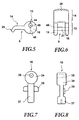
- FIG. 5 shows a side view of the lever 9 according to FIG. 1.
- the lever 9 has an actuating section 14 and a directly adjoining it Bearing section 13, see also Figure 6.
- the bearing section 13 is in cross section in essentially circular and has a bore 49 eccentrically. This is at a distance 44 or 45 to the upper or lower edge of the bearing section 13 arranged. The difference between the distance 45 and 44 gives the stroke of the ram 10, see Figures 7, 8 and 1, between the spread position and the relief position of the Expansion plug.
- FIG. 6 shows a top view of the lever 9 according to FIG. 5.
- the storage section 13 is fork-shaped with two fork arms 15, 16, which correspond to the Bearing surfaces 19, 20 of the arm mounts 17, 18, see Figure 2, are stored. Between the fork arms 15, 16 extend the bearing pin 21, which at both ends in corresponding Bores 49 is inserted in each of the fork arms.
- the bearing pin 21 is eccentric relative to the fork arm 15 which is essentially circular in cross section, 16, see Figure 5, arranged.
- the plunger 10 is shown, which essentially by means of a cross section circular head part 34 with eccentrically arranged bearing bore 35 between the two fork arms 15, 16, see Figure 6, pivotable on the bearing pin 21 is stored.
- a head ending in a foot part 37 adjoins the head part 34 on.
- This carries a centering device 39 approximately midway between the head part and foot part Length of the centering device 39 transverse to the plunger 10 corresponds approximately to the length of one Diagonals of the passage opening 30 and is larger than the distance between the retaining slopes 23 according to FIG. 3.
- FIG. 8 shows a rear view of the plunger 10 according to FIG. 7.
- Foot part 37 has has a substantially circular cross-section and is suitable for the receiving recess 42 in counter-clamping insert 38, see Figure 4, formed.
- In the foot part 37 is one Blind bore formed into the through hole 43 of the counter-clamping insert 38, see Figure 4, for example a screw for releasably attaching the counter-clamping insert can be screwed onto the plunger 10.
- Ram 10 and counter-clamping insert 38 can also be made in one piece.
- the expansion plug 4 In the insulating vessel according to the invention and the actuating device described 5 for the expansion plug 4 results in that no liquid contained in the insulating vessel 1 flows through the actuator and therefore cleaning the screw cap is easily possible. Additional seals between neck area 40 and screw cap 3 or between expansion plug 4 and actuator 5 are not necessary.
- the expansion plug 4 securely seals the insulating vessel 1 in its spread position 6 its neck area 40 relative to the pouring opening 12 in the screw cap 3.
- the expansion plug 4 is essentially tubular.
- Embodiments of the invention can also be the expansion plug as a molded part trained and for example directly with the foot part of the plunger by locking or other releasable connection, for example screwing, be connected.
- the expansion plug can also be formed in one piece with the tappet.
Landscapes
- Engineering & Computer Science (AREA)
- Physics & Mathematics (AREA)
- Thermal Sciences (AREA)
- Food Science & Technology (AREA)
- Mechanical Engineering (AREA)
- Closures For Containers (AREA)
- Thermally Insulated Containers For Foods (AREA)
- Devices For Use In Laboratory Experiments (AREA)
Abstract
Description
- Figur 1
- eine Seitenansicht eines Verschlußdeckels für ein Isoliergefäß;
- Figur 2
- eine Draufsicht auf den Verschlußdeckel nach Figur 1;
- Figur 3
- einen Schnitt entlang der Linie III-III aus Figur 2;
- Figur 4
- eine auseinandergezogene Darstellung von einem Expansionsstopfen und einem Gegenspanneinsatz;
- Figur 5
- eine Seitenansicht eines Hebels nach Figur 1;
- Figur 6
- eine Draufsicht auf den Hebel nach Figur 5;
- Figur 7
- eine Seitenansicht eines Stößels zur Verbindung mit dem Hebel nach Figuren 5 und 6, und
- Figur 8
- eine Hinteransicht des Hebels nach Figur 7.
Claims (29)
- Flüssigkeitsbehälter, insbesondere Isoliergefäß (1) mit einer oberen Öffnung (2) und einem auf diese aufsetzbaren Verschlußdeckel (3), in welchem ein elastisch spreizbarer Expansionsstopfen (4) mittels einer mit diesem bewegungsverbundenen Betätigungseinrichtung (5) zwischen einer Spreizstellung (6) und einer Entlastungsstellung (7) verstellbar gelagert ist,
dadurch gekennzeichnet,
daß die Betätigungseinrichtung (5) einen am Verschlußdeckel (3) verschwenkbar gelagerten Hebel (9) und einen mit dem Expansionsstopfen (4) lösbar verbundenen, exzentrisch zur Lagerung des Hebels (9) mit diesem bewegungsverbundenen Stößel (10) aufweist. - Flüssigkeitsbehälter nach Anspruch 1,
dadurch gekennzeichnet,
daß der Expansionsstopfen (4) in seiner Spreizstellung (6) in dichtende Anlage mit einer Innenfläche (8) des Flüssigkeitsbehälters (1) ist. - Flüssigkeitsbehälter nach Anspruch 2,
dadurch gekennzeichnet,
daß der Flüssigkeitsbehälter (1) eine doppelwandige Isolierflasche ist, auf derem oberen Ende (11) der als Schraubkappe ausgebildete Verschlußdeckel (3) aufschraubbar ist, wobei in der Schraubkappe (3) eine Ausgießöffnung (12) ausgebildet ist. - Flüssigkeitsbehälter nach einem der vorangehenden Ansprüche,
dadurch gekennzeichnet,
daß das obere Ende (11) der Isolierflasche ein Außengewinde aufweist. - Flüssigkeitsbehälter nach einem der vorangehenden Ansprüche,
dadurch gekennzeichnet,
daß dieser aus einem oder einer Kombination der folgenden Materialien gebildet ist: Metall, insbesondere Stahl und Aluminium, Kunststoff und Glas. - Flüssigkeitsbehälter nach wenigstens einem der vorangehenden Ansprüche,
dadurch gekennzeichnet,
daß der Hebel (9) ein einarmiger Hebel mit einem Lagerabschnitt (13) zur Lagerung am Verschlußdeckel (3) und einem Betätigungsabschnitt zum Verschwenken des Hebels durch einen Benutzer ist. - Flüssigkeitsbehälter nach wenigstens einem der vorangehenden Ansprüche,
dadurch gekennzeichnet,
daß der Lagerabschnitt (13) gabelförmig mit zwei Gabelarmen (15, 16) ausgebildet ist, welche in entsprechenden Gabelarmaufnahmen (17, 18) des Verschlußdeckels (3) verschwenkbar gelagert sind. - Flüssigkeitsbehälter nach wenigstens einem der vorangehenden Ansprüche,
dadurch gekennzeichnet,
daß die Gabelarme (15, 16) im Querschnitt im wesentlichen kreisförmig sind. - Flüssigkeitsbehälter nach wenigstens einem der vorangehenden Ansprüche,
dadurch gekennzeichnet,
daß die Gabelarmaufnahmen (17, 18) zumindest teilkreisförmige Lagerflächen (19, 20) aufweisen. - Flüssigkeitsbehälter nach wenigstens einem der vorangehenden Ansprüche,
dadurch gekennzeichnet,
daß ein Lagerbolzen (21) sich im wesentlichen senkrecht zu den Gabelarmen (15, 16) erstreckt und exzentrisch von diesen gehalten ist, wobei der Stößel (10) am Lagerbolzen (21) verschwenkbar gelagert ist. - Flüssigkeitsbehälter nach wenigstens einem der vorangehenden Ansprüche,
dadurch gekennzeichnet,
daß der Betätigungsabschnitt (14) in Spreizstellung (6) des Expansionsstopfens (4) auf einer im wesentlichen ebenen Deckeloberseite (22) des Verschlußdeckels (3) aufliegt. - Flüssigkeitsbehälter nach wenigstens einem der vorangehenden Ansprüche,
dadurch gekennzeichnet,
daß der Betätigungsabschnitt (14) in Spreizstellung (6) des Expansionsstopfens (4) die Ausgießöffnung (12) abdeckt. - Flüssigkeitsbehälter nach wenigstens einem der vorangehenden Ansprüche,
dadurch gekennzeichnet,
daß der Ausgießöffnung (12) eine durch eine Randkante (24) des Verschlußdeckels (3) gebildete Tropfkante (25) zugeordnet ist. - Flüssigkeitsbehälter nach wenigstens einem der vorangehenden Ansprüche,
dadurch gekennzeichnet,
daß zwischen Ausgießöffnung (12) und Tropfkante (25) eine nach unten in Richtung Flüssigkeitsbehälter (1) geneigte Ausfließschräge (26) angeordnet ist. - Flüssigkeitsbehälter nach wenigstens einem der vorangehenden Ansprüche,
dadurch gekennzeichnet,
daß die Ausgießöffnung (12) in einem am Verschlußdeckel (3) angeordneten Mundstück ausgebildet ist. - Flüssigkeitsbehälter nach wenigstens einem der vorangehenden Ansprüche,
dadurch gekennzeichnet,
daß im Außenumfang (27) des Verschlußdeckels (3) zumindest im Bereich der Tropfkante (25) eine konvex gekrümmte Nut (8) ausgebildet ist, die einseitig in die Tropfkante übergeht. - Flüssigkeitsbehälter nach wenigstens einem der vorangehenden Ansprüche,
dadurch gekennzeichnet,
daß ein freies Ende (29) des Betätigungsabschnitts (14) nach unten in Richtung Flüssigkeitsbehälter (1) gekrümmt ist, welches freie Ende die Tropfkante (25) in Spreizstellung (6) des Expansionsstopfens (4) überdeckt und zumindest teilweise in die Nut (28) eingreift. - Flüssigkeitsbehälter nach wenigstens einem der vorangehenden Ansprüche,
dadurch gekennzeichnet,
daß die Lagerflächen (19, 20) der Gabelarmaufnahmen (17, 18) seitlich zu einer Durchtrittsöffnung (30) im Verschlußdeckel (3) in diesem ausgebildet und nach oben zur Deckeloberseite (22) offen sind. - Flüssigkeitsbehälter nach wenigstens einem der vorangehenden Ansprüche,
dadurch gekennzeichnet,
daß benachbart zur Randkante (24) der Deckeloberseite (22) und gegenüberliegend zur Ausgießöffnung (12) eine Belüftungsbohrung (31) im Verschlußdeckel (3) angeordnet ist. - Flüssigkeitsbehälter nach wenigstens einem der vorangehenden Ansprüche,
dadurch gekennzeichnet,
daß die Durchtrittsöffnung (30) zwischen Ausgießöffnung (12) und Belüftungsbohrung (31) angeordnet ist. - Flüssigkeitsbehälter nach wenigstens einem der vorangehenden Ansprüche,
dadurch gekennzeichnet,
daß im Verschlußdeckel (3) ein die Durchtrittsöffnung (30) im wesentlichen umgebender Aufnahmering (32) zur Aufnahme eines Anlageendes (33) des Expansionsstopfens (4) angeordnet ist. - Flüssigkeitsbehälter nach wenigstens einem der vorangehenden Ansprüche,
dadurch gekennzeichnet,
daß der Stößel (10) ein im Querschnitt im wesentlichen kreisförmiges, zwischen den Gabelarmen (15, 18) anordbares Kopfteil (34) aufweist, in dem exzentrisch eine Lagerbohrung (35) für den Lagerbolzen (21) ausgebildet ist. - Flüssigkeitsbehälter nach wenigstens einem der vorangehenden Ansprüche,
dadurch gekennzeichnet,
daß der Stößel (10) ein mit einem Zugende (36) des Expansionsstopfens (4) lösbar verbundenes Fußteil (37) aufweist. - Flüssigkeitsbehälter nach wenigstens einem der vorangehenden Ansprüche,
dadurch gekennzeichnet,
daß der Expansionsstopfen (4) im wesentlichen schlauchförmig ist. - Flüssigkeitsbehälter nach wenigstens einem der vorangehenden Ansprüche,
dadurch gekennzeichnet,
daß der Expansionsstopfen (4) als mit dem Fußteil (37) des Stößels (10) lösbar verbundenes Formteil ausgebildet ist. - Flüssigkeitsbehälter nach wenigstens einem der vorangehenden Ansprüche,
dadurch gekennzeichnet,
daß am Zugende (36) des Expansionsstopfens (4) ein mit dem Fußteil (37) des Stößels (10) lösbar verbundener Gegenspanneinsatz (38) angeordnet ist. - Flüssigkeitsbehälter nach wenigstens einem der vorangehenden Ansprüche,
dadurch gekennzeichnet,
daß am Stößel (10) eine Zentriereinrichtung (39) zum Zentrieren des Stößels relativ zur Durchtrittsöffnung (30) und/oder zum Aufnahmering (32) angeordnet ist. - Flüssigkeitsbehälter nach wenigstens einem der vorangehenden Ansprüche,
dadurch gekennzeichnet,
daß der Expansionsstopfen (4) an seinem unteren Zugende (36) geschlossen ist. - Flüssigkeitsbehälter nach wenigstens einem der vorangehenden Ansprüche,
dadurch gekennzeichnet,
daß im wesentlichen das Zugende (36) in Entlastungsstellung (7) des Expansionsstopfens (4) mit der oberen Öffnung (2) in abdichtender Anlage ist und in Spreizstellung (6) ein Fluidkanal zwischen oberer Öffnung (2) und Ausgießöffnung (12) im Verschlußdeckel (3) freigegeben ist.
Applications Claiming Priority (2)
| Application Number | Priority Date | Filing Date | Title |
|---|---|---|---|
| DE29702507U DE29702507U1 (de) | 1997-02-13 | 1997-02-13 | Flüssigkeitsbehälter |
| DE29702507U | 1997-02-13 |
Publications (2)
| Publication Number | Publication Date |
|---|---|
| EP0861625A2 true EP0861625A2 (de) | 1998-09-02 |
| EP0861625A3 EP0861625A3 (de) | 2001-03-28 |
Family
ID=8035898
Family Applications (1)
| Application Number | Title | Priority Date | Filing Date |
|---|---|---|---|
| EP98102520A Withdrawn EP0861625A3 (de) | 1997-02-13 | 1998-02-13 | Flüssigkeitsbehälter |
Country Status (2)
| Country | Link |
|---|---|
| EP (1) | EP0861625A3 (de) |
| DE (1) | DE29702507U1 (de) |
Cited By (1)
| Publication number | Priority date | Publication date | Assignee | Title |
|---|---|---|---|---|
| GB2403212A (en) * | 2003-06-06 | 2004-12-29 | Keith White | Sealing unit for a drinks can |
Citations (1)
| Publication number | Priority date | Publication date | Assignee | Title |
|---|---|---|---|---|
| DE3104070A1 (de) | 1981-02-06 | 1982-08-12 | Emsa-Werke Wulf GmbH & Co, 4407 Emsdetten | Verschlussanordnung eines flaschenartigen gefaesses, insbesondere thermoskanne |
Family Cites Families (3)
| Publication number | Priority date | Publication date | Assignee | Title |
|---|---|---|---|---|
| US4083468A (en) * | 1977-05-20 | 1978-04-11 | John Howard Batchelor | Vacuumizing closure for vacuum pack containers |
| DE3203999C2 (de) * | 1982-02-05 | 1984-06-14 | Walter 8901 Aystetten Heubl | Flaschenverschluß |
| GB2114959B (en) * | 1982-02-17 | 1985-07-17 | Thermos Ltd | Stopper with pouring facility |
-
1997
- 1997-02-13 DE DE29702507U patent/DE29702507U1/de not_active Expired - Lifetime
-
1998
- 1998-02-13 EP EP98102520A patent/EP0861625A3/de not_active Withdrawn
Patent Citations (1)
| Publication number | Priority date | Publication date | Assignee | Title |
|---|---|---|---|---|
| DE3104070A1 (de) | 1981-02-06 | 1982-08-12 | Emsa-Werke Wulf GmbH & Co, 4407 Emsdetten | Verschlussanordnung eines flaschenartigen gefaesses, insbesondere thermoskanne |
Cited By (1)
| Publication number | Priority date | Publication date | Assignee | Title |
|---|---|---|---|---|
| GB2403212A (en) * | 2003-06-06 | 2004-12-29 | Keith White | Sealing unit for a drinks can |
Also Published As
| Publication number | Publication date |
|---|---|
| EP0861625A3 (de) | 2001-03-28 |
| DE29702507U1 (de) | 1998-06-18 |
Similar Documents
| Publication | Publication Date | Title |
|---|---|---|
| DE4136985C1 (de) | ||
| DE602005004893T3 (de) | Vorrichtung zum verschliessen von lebensmittelbehältern und mit solch einer vorrichtung versehener lebensmittelbehälter | |
| DE19621774C2 (de) | Vorrichtung zum Zubereiten einer Mischung aus einer Wirksubstanz und einem Verdünnungsmittel sowie Verfahren zum Befüllen einer Kartusche für eine derartige Vorrichtung | |
| DE2240304A1 (de) | Vakuumisolierte thermoskanne | |
| CH700493B1 (de) | Verschluss für eine Trinkflasche. | |
| DE2152725B2 (de) | Isolierbehälter | |
| DE29611746U1 (de) | Flasche | |
| EP0641726A1 (de) | Vorrichtung zum Bereithalten und Abgeben von heissen oder kalten Getränken | |
| DE9302022U1 (de) | Freizeitflasche | |
| EP0861625A2 (de) | Flüssigkeitsbehälter | |
| DE10105766A1 (de) | Kanne | |
| DE3347713C2 (de) | Verschlußanordnung mit Drehknauf und Stopfen für ein Gefäß | |
| DE29707356U1 (de) | Isoliergefäß | |
| DE10229257C1 (de) | Verschluß für Behälter, insbesondere für Flaschen | |
| EP0840565A2 (de) | Verschlusseinrichtung an behältern | |
| DE8633922U1 (de) | Dosierverschluß mit Ausgußtülle | |
| DE4214171A1 (de) | Fuellbarer behaelter | |
| DE8528028U1 (de) | Deckel für Isolierbehälter | |
| DE2825223A1 (de) | Pumpenausgiesser fuer isolierte behaelter | |
| EP2431294B1 (de) | Drehverschluss für Kosmetikbehälter | |
| DE1607864C3 (de) | ||
| DE9302025U1 (de) | Thermosflasche | |
| DE19949338A1 (de) | Verschlußeinrichtung für Getränkedosen | |
| DE2233565C3 (de) | Hermetisches Verschlußsystem für Thermosflaschen und ähnliche Behälter | |
| DE41873C (de) | Neuerung an Verschlufsvorrichtungen für Flaschen und andere Behälter, welche zur Aufnahme gashaltiger Flüssigkeiten dienen |
Legal Events
| Date | Code | Title | Description |
|---|---|---|---|
| PUAI | Public reference made under article 153(3) epc to a published international application that has entered the european phase |
Free format text: ORIGINAL CODE: 0009012 |
|
| AK | Designated contracting states |
Kind code of ref document: A2 Designated state(s): AT BE CH DE DK ES FR GB IT LI NL PT SE |
|
| AX | Request for extension of the european patent |
Free format text: AL;LT;LV;MK;RO;SI |
|
| PUAL | Search report despatched |
Free format text: ORIGINAL CODE: 0009013 |
|
| AK | Designated contracting states |
Kind code of ref document: A3 Designated state(s): AT BE CH DE DK ES FI FR GB GR IE IT LI LU MC NL PT SE |
|
| AX | Request for extension of the european patent |
Free format text: AL;LT;LV;MK;RO;SI |
|
| 17P | Request for examination filed |
Effective date: 20010403 |
|
| AKX | Designation fees paid |
Free format text: AT BE CH DE DK ES FR GB IT LI NL PT SE |
|
| 17Q | First examination report despatched |
Effective date: 20041012 |
|
| STAA | Information on the status of an ep patent application or granted ep patent |
Free format text: STATUS: THE APPLICATION HAS BEEN WITHDRAWN |
|
| 18W | Application withdrawn |
Effective date: 20050222 |