EP0861636A2 - Dispositif pour la mise en place des os et/ou des fragments d'os - Google Patents
Dispositif pour la mise en place des os et/ou des fragments d'os Download PDFInfo
- Publication number
- EP0861636A2 EP0861636A2 EP98103359A EP98103359A EP0861636A2 EP 0861636 A2 EP0861636 A2 EP 0861636A2 EP 98103359 A EP98103359 A EP 98103359A EP 98103359 A EP98103359 A EP 98103359A EP 0861636 A2 EP0861636 A2 EP 0861636A2
- Authority
- EP
- European Patent Office
- Prior art keywords
- spherical
- screw
- perforated plate
- fastening screw
- recess
- Prior art date
- Legal status (The legal status is an assumption and is not a legal conclusion. Google has not performed a legal analysis and makes no representation as to the accuracy of the status listed.)
- Granted
Links
Images


Classifications
-
- A—HUMAN NECESSITIES
- A61—MEDICAL OR VETERINARY SCIENCE; HYGIENE
- A61B—DIAGNOSIS; SURGERY; IDENTIFICATION
- A61B17/00—Surgical instruments, devices or methods
- A61B17/56—Surgical instruments or methods for treatment of bones or joints; Devices specially adapted therefor
- A61B17/58—Surgical instruments or methods for treatment of bones or joints; Devices specially adapted therefor for osteosynthesis, e.g. bone plates, screws or setting implements
- A61B17/68—Internal fixation devices, including fasteners and spinal fixators, even if a part thereof projects from the skin
- A61B17/70—Spinal positioners or stabilisers, e.g. stabilisers comprising fluid filler in an implant
- A61B17/7001—Screws or hooks combined with longitudinal elements which do not contact vertebrae
- A61B17/7002—Longitudinal elements, e.g. rods
- A61B17/701—Longitudinal elements with a non-circular, e.g. rectangular, cross-section
-
- A—HUMAN NECESSITIES
- A61—MEDICAL OR VETERINARY SCIENCE; HYGIENE
- A61B—DIAGNOSIS; SURGERY; IDENTIFICATION
- A61B17/00—Surgical instruments, devices or methods
- A61B17/56—Surgical instruments or methods for treatment of bones or joints; Devices specially adapted therefor
- A61B17/58—Surgical instruments or methods for treatment of bones or joints; Devices specially adapted therefor for osteosynthesis, e.g. bone plates, screws or setting implements
- A61B17/68—Internal fixation devices, including fasteners and spinal fixators, even if a part thereof projects from the skin
- A61B17/70—Spinal positioners or stabilisers, e.g. stabilisers comprising fluid filler in an implant
- A61B17/7001—Screws or hooks combined with longitudinal elements which do not contact vertebrae
- A61B17/7002—Longitudinal elements, e.g. rods
- A61B17/7004—Longitudinal elements, e.g. rods with a cross-section which varies along its length
- A61B17/7007—Parts of the longitudinal elements, e.g. their ends, being specially adapted to fit around the screw or hook heads
-
- A—HUMAN NECESSITIES
- A61—MEDICAL OR VETERINARY SCIENCE; HYGIENE
- A61B—DIAGNOSIS; SURGERY; IDENTIFICATION
- A61B17/00—Surgical instruments, devices or methods
- A61B17/56—Surgical instruments or methods for treatment of bones or joints; Devices specially adapted therefor
- A61B17/58—Surgical instruments or methods for treatment of bones or joints; Devices specially adapted therefor for osteosynthesis, e.g. bone plates, screws or setting implements
- A61B17/68—Internal fixation devices, including fasteners and spinal fixators, even if a part thereof projects from the skin
- A61B17/70—Spinal positioners or stabilisers, e.g. stabilisers comprising fluid filler in an implant
- A61B17/7058—Plates mounted on top of bone anchor heads or shoulders
-
- A—HUMAN NECESSITIES
- A61—MEDICAL OR VETERINARY SCIENCE; HYGIENE
- A61B—DIAGNOSIS; SURGERY; IDENTIFICATION
- A61B17/00—Surgical instruments, devices or methods
- A61B17/56—Surgical instruments or methods for treatment of bones or joints; Devices specially adapted therefor
- A61B17/58—Surgical instruments or methods for treatment of bones or joints; Devices specially adapted therefor for osteosynthesis, e.g. bone plates, screws or setting implements
- A61B17/68—Internal fixation devices, including fasteners and spinal fixators, even if a part thereof projects from the skin
- A61B17/70—Spinal positioners or stabilisers, e.g. stabilisers comprising fluid filler in an implant
- A61B17/7001—Screws or hooks combined with longitudinal elements which do not contact vertebrae
- A61B17/7002—Longitudinal elements, e.g. rods
- A61B17/7011—Longitudinal element being non-straight, e.g. curved, angled or branched
-
- A—HUMAN NECESSITIES
- A61—MEDICAL OR VETERINARY SCIENCE; HYGIENE
- A61B—DIAGNOSIS; SURGERY; IDENTIFICATION
- A61B17/00—Surgical instruments, devices or methods
- A61B17/56—Surgical instruments or methods for treatment of bones or joints; Devices specially adapted therefor
- A61B17/58—Surgical instruments or methods for treatment of bones or joints; Devices specially adapted therefor for osteosynthesis, e.g. bone plates, screws or setting implements
- A61B17/68—Internal fixation devices, including fasteners and spinal fixators, even if a part thereof projects from the skin
- A61B17/70—Spinal positioners or stabilisers, e.g. stabilisers comprising fluid filler in an implant
- A61B17/7001—Screws or hooks combined with longitudinal elements which do not contact vertebrae
- A61B17/7035—Screws or hooks, wherein a rod-clamping part and a bone-anchoring part can pivot relative to each other
Definitions
- the invention relates to a device for positioning and Fixation of bones and / or bone fragments after the Preamble of claim 1.
- Aesculap is a spine system with the name SOCON known in which two screws over intermediate elements are connected by means of a threaded rod.
- the intermediate elements are designed so that they are on the one hand on the Threaded rod can be moved axially by turning and on the other hand, around an axis that is perpendicular to the screw axis and is pivoted perpendicular to the axis of the threaded rod can be.
- This spine system has the disadvantage that when Swivel the screws around the axis of the threaded rods at the same time moving the screws along the threaded rod occurs. Except when swiveling the screw around axis perpendicular to the screw and threaded rod axis for example, when using two screws, the are not connected via the threaded rod, to pivot a screw without at the same time Change the distance between the two screws.
- the foregoing spinal system becomes transpedicular Used screws that have a conventional thread runout and therefore have no screw-in depth stop. This can be the same as the presence of hard surface edges lead to injuries on the connecting parts.
- This system can be freely pivoted around a ball head Screws can be clamped in the desired position. There however, the clamping is not in the direction of the axis of symmetry Clamping takes place, tilting of the clamping piece as well of the threaded rod occur, creating tension in the device be introduced, which are transferred to the bones.
- the object of the invention is therefore a device for positioning and fixing bones and / or bone fragments to create with the possible in all device-related Bones and / or bone fragments remained the same Strength without the occurrence of undesirable prestresses are fixable and positionable, with the device with a small construction volume, the risk of injury is minimized and not pre-assembling individual parts of the device should be required.
- this object is in a device for positioning and fixing bones and / or bone fragments solved by the features in claim 1.
- Beneficial Developments are the subject of claim 1 directly or indirectly related claims.
- These holding devices are on a prosthesis plate serving perforated plate having at least two holes can be fastened and fixed using a lock nut, that the holding devices slidably held in the perforated plate Align perpendicular to the perforated plate.
- Holding device not only eliminates pre-assembly, but in particular there is no assembly of the holding device forming parts by the operating doctor during the operation.
- the perforated plate has at least two elongated holes this slidable with respect to the holding device, so that no pre-tension when fixing the screws to the perforated plate occur over the screws in the bones and / or bone fragments would be introduced.
- the fastening screws preferably have a cylindrical core with a screw thread, that has a constant outside diameter.
- the outer flank ends of the screw threads are very rounded, so that on the one hand due to the screw shape and on the other hand due to the flank ends, the bones are stressed as little as possible will. It can also advantageously the screw-in depth of the screws can be corrected at any time if necessary will.
- the free ends of the fastening screws rounded.
- the screws on upper end of the screw thread optionally one cylindrical approach, through which on the one hand the maximum Screw-in depth is limited and on the other hand a better one Load distribution in the screw head support is realized.
- the device has a head part of the fastening screw Recess with a truncated cone and an adjoining one spherical area, being in the spherical Area a conical end part of a connecting part is used and by the frustoconical area the possible swivel range is fixed. So is the screw around the spherical end part of the connecting part rotatable and swiveling.
- the spherical end part of the connecting part goes into one stretchable shaft part over, which in turn in a threaded part ends with an external thread.
- an opening preferably designed as an elongated hole Perforated plate inserted the stretchable shaft of the connecting part and on the threaded part is preferably with a Screwed on fine thread profiled nut.
- the first Line of the connecting rod between the fastening screw and modified the perforated plate according to the invention in such a way that the screw at an adjustable distance from the perforated plate can be fixed.
- a spherical Head part of the fastening screw in which the opposite Embodiment described above, no recesses is provided in a complementary to the spherical head part Area stored inside a sleeve.
- the sleeve on that facing away from the fastening screw End a cylindrical recess with an internal thread in which the connecting part designed as a threaded rod is screwed in. Furthermore, the sleeve is to be attached a tool, for example a wrench, outside formed as a hexagon. It is also a threaded rod trained connecting part by means of two nuts for example, adjustable in height in an elongated hole in the perforated plate and fixable in this position.
- the distance between the perforated plate and the fastening screw over the threaded rod is therefore particularly advantageous.
- the threaded rod on the headboard the end facing the fastening screw one of the curvature of the spherical head part corresponding concave recess on.
- screw head and the nut can also specify in the edges of the elongated holes for example, conical or spherical hollows be.
- both embodiments according to the invention provided all or some of the contact surfaces statistically between the individual elements of the device to be profiled or provided with fine transverse grooves. Consequently there is a secure hold between the individual elements, since the friction is increased by positive locking.
- perforated plates are of any shape and any any number of arranged and shaped elongated holes conceivable.
- All elements of the invention are preferably Device made of the same material, such as Implant steels according to DIN 17443, such as 1.4428 or 1.4461, or from special alloys such as CoCrMo, or grade 4 or 5 titanium, such as TI6-A14-V.
- the device according to the invention has the additional Advantage of having only a small number of tools is required, which is also easy to use. It deals these are primarily standard tools.
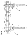
- Fig.1b is a serving as a prosthesis plate, in section shown perforated plate 5, for example in Fig.1b has three slots 50 to 52.
- the two outer slots 50 and 52 of the perforated plate 5 is one Holding device 4 used, the essential elements in Fig.1b from top to bottom, a lock nut 3 and a Connecting part 2 and a fastening screw 1 are.
- the Fastening screws 1 of the two holding devices 4 are in vertebrae previously indicated schematically by an operator 24 trained channels, not shown in FIG. 1b screwed in.
- FIG. 1a a first is preferred Embodiment of the holding device 4 based on a Sectional view along the line I-I described in Fig.1b.
- 1a shows the fastening screw 1 of the holding device 4 a cylindrical core with a screw thread 11 which has a constant outside diameter.
- the Flanks of the screw thread 11 have rounded flank ends 12 on.
- the lower free end 13 of the screw 1 in FIG. 1 is also rounded.
- annular extension 14 which is preferably cylindrical is formed and whose outer diameter is larger than the outer diameter of the screw thread 11.
- the annular extension 14 merges into a head part 15, the outer dimension of which is larger than that of the annular extension and is preferably designed on the outside as a hexagon 15 1 in order to be able to attach a suitable tool, for example a commercially available open-ended spanner.
- the head part 15 has a spherical recess 15 2 .
- the spherical recess 15 2 merges into a frustoconical recess 15 3 which is symmetrical with the dashed center axis of the screw 11 and which is open at the top in FIG.
- the smaller radius of the frustoconical recess 15 3 is adjacent to the upper part of the spherical recess 15 2 .
- the extensions of the frustoconical recess 15 3 shown in dashed lines in the sectional view in FIG. 1a preferably include an acute angle ⁇ of 30 ° -40 °.
- the hexagon 15 1 of the head part 15 merges into a spherical shell-shaped section 15 4 .
- the diameter of the spherical recess 15 2 in the head part 15 is larger than the adjacent smaller diameter of the frustoconical recess 15 3 .
- an undercut occurs at the transition area between the frustoconical recess 15 3 and the spherical recess 15 2 .
- a spherical end part 21 of the connecting part 2 complementary to the spherical recess 15 2 is inserted.
- the end facing away from the spherical end part 21 of the connecting part 2 is of circular cylindrical design and is provided with an external thread 22 which is preferably designed as a fine thread profile.
- the head part 15 has to be manufactured from two individual parts for manufacturing reasons.
- the dividing line between the two individual parts forming the head part 15 can be, for example, the dividing line entered with dash-dot lines.
- this part After inserting the spherical end part 21 of the connecting part 2 into the lower part of the head part which forms a unit with the fastening screw 1, this part is firmly connected to the part of the head part 15 shown above the dash-dotted line, for example welded or possibly also glued, so that the Head part 15 then forms a unit shown in Fig.1a with the fastening screw.
- the connecting part 2 in the head part 15 can be rotated on the one hand about the axis represented by the broken line and on the other hand in the area defined by the frustoconical recess 15 3 also pivotable with respect to the center axis shown in dashed lines.
- the angular range in which the connecting part 2 can be pivoted relative to the fastening screw 1 corresponds to the angular range designated by ⁇ in FIG. 1a and is in the order of magnitude of 30 ° to 35 in the embodiment of FIG. 1a °.
- the lock nut 3 preferably as a hex nut is formed, one of the fine thread profiling of the External thread 22 of the connecting part 2 corresponding thread and on the lower side in Fig.1a an annular approach 31 with a chamfer 32.
- Fig.1b which is a sectional view along the line II-II 1a is the perforated plate serving as a prosthesis plate 5 partially shown in section.
- the perforated plate 5 in FIG. 1b has three elongated holes 50 to 52 on.
- the upper edges 50b to 52b in FIG. 1b are suitable for the chamfer 32 of the annular projection 31 of the lock nut 3 beveled.
- edges 50a to 52a of the elongated holes 50 to 52 are rounded so that their rounding corresponds to the spherical end section 15 4 of the head part 15 at the upper end of the fastening screw 1.
- the radius of the concave edge regions 50a to 52a of the three elongated holes 50 to 52 thus corresponds to the radius of the spherical section 15 4 of the head part 15. Due to the concave design of the edge regions 50a to 52a, a corresponding tilting or inclination of the fastening screws 1 with respect to the as Perforated plate serving for prosthesis plate 5 (see Fig.1c).
- the perforated plate serving as a prosthesis plate is attached to a pedicle as follows: First, the surgeon inserts a pedicle channel into a vertebra 24. Appropriately, a thread corresponding to the screw thread 11 of the fastening screw 1 to be inserted should also be cut in the pedicle channel. By attaching a tool, for example an open-ended wrench, to the hexagon 15 1 on the head part 15 of the fastening screw 1, this is screwed in together with the connecting part 2 inserted into the head part 15 so that the head part 15 and the connecting part 2 protruding therefrom in the correct altitude.
- a tool for example an open-ended wrench
- a second preferred one is given below Embodiment according to the invention described.
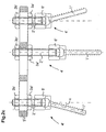
- a holding device 4 ' which consists of a Fixing screw 1 'and a threaded rod Connecting part 2 ', nuts 3a' and 3b 'as well a perforated plate 5 is shown.
- the area of the fastening screw provided with a screw thread 11 ' 1 ' corresponds in principle to the corresponding one Area of the mounting screw 1 in Fig.1a and therefore points also has a cylindrical core on which a screw thread 11 'is provided with a constant outer diameter.
- the flank ends 12 ' like the free end 13', are rounded.
- the outer diameter of the outer diameter corresponds to the screw thread 11 '.
- the ring-shaped Approach 14 ' goes into a spherical head part 15' about, which is received in a sleeve 6 '.
- the sleeve 6 ' consists of manufacturing reasons two sleeve parts 6a 'and 6b', which are firmly connected are.
- the lower sleeve part 6b 'in FIG. 2a has one through recess, whose lower end in Fig.2a frustoconical area 60 '.
- the upper sleeve part 6a 'in FIG. 2a which is on the common Contact surface 6ab 'is connected to the sleeve part 6b', in turn has a continuous recess, which by a cylindrical region 62 'in FIG a cylindrical area provided with an internal thread 63 'passes over.
- the sleeve part 6a ' is preferably in the form of a hexagon trained to use an appropriate tool, if necessary to be able to attach a cranked spanner.
- the thread the internal thread which is preferably designed as a fine thread corresponds to the sleeve part 6a '.
- the threaded rod 2 ' points at the spherical head part 15 'of the fastening screw 1 'adjacent end 21' a concave bulge whose curvature is that of the spherical head part Corresponds to 15 '.
- the opposite end 20 'of the threaded rod 2 ' is rounded.
- FIG. 2a In the upper end part of the threaded rod 2 'in FIG. 2a is also a symmetrical to the dashed center axis Recess 24 'is provided, which is preferably a shape corresponding to an Allen key or TROX key having.
- a lower one in FIG. 2a is placed on the threaded rod 2 ' Screwed nut 3a '.
- the threaded rod 2 'through a in Fig. 2a unspecified slot of a perforated plate 5 'is inserted on the free upper end of the threaded rod 2 'screwed the nut 3b', which then at least the threaded rod 2 'is fixed with respect to the perforated plate 5'.
- Fig.2b which is a sectional view of the second preferred Embodiment along the line IV-IV in Fig. 2a is two fastening screws 1 'over sleeves 6', threaded rods 2 'and two nuts 3a' and 3b 'with the perforated plate 5' connected.
- the perforated plate 5 ' has three elongated holes in Fig.2b 50 'to 52', the middle areas of which are rectangular in plan view are and their end regions in plan view each are semicircular. Therefore, the nuts 3a 'and 3b' simple nuts, each on the Perforated plate 5 'facing side just executed and only are chamfered on the outside. To simplify the manufacture of the nuts, The nuts are so that they are confusion-free Completely identical as hexagon nuts.
- the edges 50a 'to 52b' can, for example, as described with reference to Fig.1a.
- the nuts 3a 'and 3b' must also fall open at least one side which corresponds to the chamfering of the edges 50a 'to 52a' or 50b 'to 52b' have a corresponding shape.
- Fig.2c of the second embodiment correspond to the device according to the invention the two outer brackets attached to the perforated plate 5 ' 4 'including the angle of inclination shown ⁇ of the representation in Fig.1c.
- Fig.1c in Fig.2c is a third, shown in the middle Fixing device fixed to the perforated plate 5 ', in which the dashed center axis of the fastening screw 1 ' and the threaded rod 2 'are aligned.
- Fig. 2c also shows that the second preferred Embodiment of the invention the length of the threaded rods 2 'or 2' 'can be freely selected. This is also the Location of the respective mounting device 4 'with respect to Perforated plate 5 'or the distance between the underside of the sleeve 6' from the perforated plate 5 'according to the respective circumstances selectable and adaptable. A fine adjustment or precise setting of the position is then particularly through given the choice of the position of the lower screws 3a 'in FIG. 2c.
- FIG.3a shows a perforated plate 5a, which has three elongated holes 6a, 6b and 6c, that on a dashed center line are arranged and, as also shown in Fig.3a, different Can have lengths.
- FIG. 3b shows a T-shaped perforated plate 5b, which two elongated holes arranged in series and of the same size in FIG. 3b 7b and 7c and one arranged perpendicular to them, for example Has elongated hole 7a.
- 3c shows an arcuate perforated plate 5c, for example three elongated holes 8a, 8b and 8c of the same size has along a dashed curved line are aligned.
- Fig.3d an L-shaped perforated plate 5d is shown two arranged in a row in series, the same in Fig.3d large slots 9b, 9c and a slot perpendicular to these 9a.
- any other combinations of are different dimensioned elongated holes conceivable.
- the in Fig.3a to Perforated plates shown in 3d are shown as flat in themselves.
- the individual perforated plates can also be preformed in this way be, for example, their two end areas upwards are angled or one end area down and the other is angled upwards or only one end area at all is angled or cranked while the other end region has just been executed.
- one of the fastening screw 1 is enlarged Fig.1a corresponding mounting screw 1 '' and one of the Fastening screw 1 'in Fig.2a corresponding fastening screw 1 '' 'reproduced.
Landscapes
- Health & Medical Sciences (AREA)
- Orthopedic Medicine & Surgery (AREA)
- Life Sciences & Earth Sciences (AREA)
- Neurology (AREA)
- Surgery (AREA)
- Heart & Thoracic Surgery (AREA)
- Engineering & Computer Science (AREA)
- Biomedical Technology (AREA)
- Nuclear Medicine, Radiotherapy & Molecular Imaging (AREA)
- Medical Informatics (AREA)
- Molecular Biology (AREA)
- Animal Behavior & Ethology (AREA)
- General Health & Medical Sciences (AREA)
- Public Health (AREA)
- Veterinary Medicine (AREA)
- Surgical Instruments (AREA)
- Prostheses (AREA)
Priority Applications (1)
| Application Number | Priority Date | Filing Date | Title |
|---|---|---|---|
| EP03018817A EP1364621B1 (fr) | 1997-02-26 | 1998-02-26 | Dispositif pour la mise en place et fixation des os et/ou des fragments d'os |
Applications Claiming Priority (2)
| Application Number | Priority Date | Filing Date | Title |
|---|---|---|---|
| DE19707677 | 1997-02-26 | ||
| DE19707677 | 1997-02-26 |
Related Child Applications (1)
| Application Number | Title | Priority Date | Filing Date |
|---|---|---|---|
| EP03018817.1 Division-Into | 2003-08-19 |
Publications (3)
| Publication Number | Publication Date |
|---|---|
| EP0861636A2 true EP0861636A2 (fr) | 1998-09-02 |
| EP0861636A3 EP0861636A3 (fr) | 1998-09-23 |
| EP0861636B1 EP0861636B1 (fr) | 2003-10-22 |
Family
ID=7821535
Family Applications (2)
| Application Number | Title | Priority Date | Filing Date |
|---|---|---|---|
| EP03018817A Expired - Lifetime EP1364621B1 (fr) | 1997-02-26 | 1998-02-26 | Dispositif pour la mise en place et fixation des os et/ou des fragments d'os |
| EP98103359A Expired - Lifetime EP0861636B1 (fr) | 1997-02-26 | 1998-02-26 | Dispositif pour la mise en place des os et/ou des fragments d'os |
Family Applications Before (1)
| Application Number | Title | Priority Date | Filing Date |
|---|---|---|---|
| EP03018817A Expired - Lifetime EP1364621B1 (fr) | 1997-02-26 | 1998-02-26 | Dispositif pour la mise en place et fixation des os et/ou des fragments d'os |
Country Status (2)
| Country | Link |
|---|---|
| EP (2) | EP1364621B1 (fr) |
| DE (3) | DE59811607D1 (fr) |
Cited By (3)
| Publication number | Priority date | Publication date | Assignee | Title |
|---|---|---|---|---|
| WO2001003593A1 (fr) * | 1999-07-07 | 2001-01-18 | Synthes Ag Chur | Vis a os avec tete de vis constituees axialement de deux parties |
| FR2799947A1 (fr) | 1999-10-22 | 2001-04-27 | Transco Esquisse | Vis pediculaire auto-secable |
| WO2013014589A1 (fr) | 2011-07-25 | 2013-01-31 | Medicrea International | Élément d'ancre pour matériel d'ostéosynthèse vertébrale |
Families Citing this family (4)
| Publication number | Priority date | Publication date | Assignee | Title |
|---|---|---|---|---|
| AU2003210964A1 (en) * | 2002-02-13 | 2003-09-04 | Cross Medical Products, Inc. | Posterior polyaxial system for the spine |
| FR2880255B1 (fr) * | 2004-12-30 | 2013-07-05 | Neuro France Implants | Dispositif d'implant pour systeme d'osteosynthese vertebrale posterieure |
| US7604652B2 (en) * | 2005-10-11 | 2009-10-20 | Impliant Ltd. | Spinal prosthesis |
| US8470008B2 (en) | 2006-03-01 | 2013-06-25 | Warsaw Othropedic, Inc. | Modular fastener assemblies for spinal stabilization systems and methods |
Family Cites Families (5)
| Publication number | Priority date | Publication date | Assignee | Title |
|---|---|---|---|---|
| DE2747312A1 (de) * | 1977-10-21 | 1979-04-26 | Ullrich | Schraube zum verbinden von knochenteilen |
| DE3614101C1 (de) * | 1986-04-25 | 1987-10-22 | Juergen Prof Dr Med Harms | Pedikelschraube |
| DE3936702C2 (de) * | 1989-11-03 | 1994-07-28 | Lutz Biedermann | Pedikelschraube und Korrektur- und Haltevorrichtung mit einer solchen Pedikelschraube |
| US5591166A (en) * | 1995-03-27 | 1997-01-07 | Smith & Nephew Richards, Inc. | Multi angle bone bolt |
| DE19512709A1 (de) * | 1995-04-08 | 1996-10-10 | Rehder Guenther | Prothesen-Halteeinrichtung |
-
1998
- 1998-02-26 DE DE59811607T patent/DE59811607D1/de not_active Expired - Fee Related
- 1998-02-26 EP EP03018817A patent/EP1364621B1/fr not_active Expired - Lifetime
- 1998-02-26 DE DE59809941T patent/DE59809941D1/de not_active Expired - Fee Related
- 1998-02-26 EP EP98103359A patent/EP0861636B1/fr not_active Expired - Lifetime
- 1998-02-26 DE DE19807827A patent/DE19807827A1/de not_active Withdrawn
Cited By (7)
| Publication number | Priority date | Publication date | Assignee | Title |
|---|---|---|---|---|
| WO2001003593A1 (fr) * | 1999-07-07 | 2001-01-18 | Synthes Ag Chur | Vis a os avec tete de vis constituees axialement de deux parties |
| US6663635B2 (en) | 1999-07-07 | 2003-12-16 | Synthes (U.S.A.) | Bone screw with two-part screw head |
| FR2799947A1 (fr) | 1999-10-22 | 2001-04-27 | Transco Esquisse | Vis pediculaire auto-secable |
| WO2013014589A1 (fr) | 2011-07-25 | 2013-01-31 | Medicrea International | Élément d'ancre pour matériel d'ostéosynthèse vertébrale |
| FR2978343A1 (fr) * | 2011-07-25 | 2013-02-01 | Medicrea International | Organe d'ancrage pour materiel d'osteosynthese vertebrale |
| JP2014527855A (ja) * | 2011-07-25 | 2014-10-23 | メディクレア インターナショナル | 脊椎骨接合器具の固定部材 |
| US9192412B2 (en) | 2011-07-25 | 2015-11-24 | Medicrea International | Anchor member for vertebral osteosynthesis equipment |
Also Published As
| Publication number | Publication date |
|---|---|
| DE59809941D1 (de) | 2003-11-27 |
| DE59811607D1 (de) | 2004-07-29 |
| EP0861636B1 (fr) | 2003-10-22 |
| EP1364621B1 (fr) | 2004-06-23 |
| EP0861636A3 (fr) | 1998-09-23 |
| DE19807827A1 (de) | 1998-11-26 |
| EP1364621A1 (fr) | 2003-11-26 |
Similar Documents
| Publication | Publication Date | Title |
|---|---|---|
| DE69628757T2 (de) | Mehrschichtverriegelungsvorrichtung für knochenbefestigungen | |
| EP3117787B1 (fr) | Vis pediculaire avec tulipe | |
| EP1567075B1 (fr) | Dispositif pour l'osteosynthèse | |
| EP1430846B1 (fr) | Vis à os pour chirurgie rachidienne ou orthopédique | |
| EP1274354B1 (fr) | Dispositif permettant la connexion articulee de deux corps | |
| EP0379551B1 (fr) | Dispositif de correction et de maintien, notamment de la colonne vertebrale | |
| DE19507141B4 (de) | Arretierwerkzeug | |
| EP2114274B1 (fr) | Implant sous forme de plaque, à utilisation destinée notamment à la colonne vertébrale | |
| DE60108662T2 (de) | Verbindungsvorrichtung für variable winkel in einem spinalimplantatsystem | |
| EP0634912B1 (fr) | Dispositif permettant de raidir et/ou de corriger la colonne vertebrale | |
| EP1681024B1 (fr) | Élément de fixation osseuse | |
| EP1568329B1 (fr) | Elément d'ancrage osseux | |
| DE60118950T2 (de) | Verbinder für wirbelsäulenstab und wirbelanker | |
| EP1281365B1 (fr) | Dispositif de fixation | |
| EP0328883B1 (fr) | Dispositif d'étaiement de la colonne vertébrale humaine | |
| DE3807335C2 (fr) | ||
| EP3487433B1 (fr) | Ancrage osseux pour ostéosynthèse sacro-iliaque | |
| EP0146872A2 (fr) | Appareil pour ostéosynthèse | |
| WO2008075160A1 (fr) | Plaque d'implant, à utiliser notamment sur la colonne vertébrale, avec une fermeture à vis | |
| EP0861636A2 (fr) | Dispositif pour la mise en place des os et/ou des fragments d'os | |
| DE4113083C2 (de) | Ringfixateur für die Osteosynthese | |
| EP3630018B1 (fr) | Implant capitellaire radial | |
| EP0303773A2 (fr) | Dispositif de protection des vertèbres de la colonne vertébrale humaine | |
| DE10005134B4 (de) | Vergurtungssystem zur Spondylodese der Lendenwirbelsäule sowie Pedikelschraube und Gegenhalter zur Verwendung bei einem solchen | |
| DE10132712B4 (de) | Knochenschraube und Osteosynthesevorrichtung |
Legal Events
| Date | Code | Title | Description |
|---|---|---|---|
| PUAI | Public reference made under article 153(3) epc to a published international application that has entered the european phase |
Free format text: ORIGINAL CODE: 0009012 |
|
| PUAL | Search report despatched |
Free format text: ORIGINAL CODE: 0009013 |
|
| AK | Designated contracting states |
Kind code of ref document: A2 Designated state(s): DE FR GB |
|
| AX | Request for extension of the european patent |
Free format text: AL;LT;LV;MK;RO;SI |
|
| RIN1 | Information on inventor provided before grant (corrected) |
Inventor name: WOLF, OLEG, DR. Inventor name: BALAZS, MATTHIAS, |
|
| AK | Designated contracting states |
Kind code of ref document: A3 Designated state(s): AT BE CH DE DK ES FI FR GB GR IE IT LI LU MC NL PT SE |
|
| AX | Request for extension of the european patent |
Free format text: AL;LT;LV;MK;RO;SI |
|
| 17P | Request for examination filed |
Effective date: 19981210 |
|
| AKX | Designation fees paid |
Free format text: DE FR GB |
|
| RBV | Designated contracting states (corrected) |
Designated state(s): DE FR GB |
|
| 17Q | First examination report despatched |
Effective date: 20000814 |
|
| GRAH | Despatch of communication of intention to grant a patent |
Free format text: ORIGINAL CODE: EPIDOS IGRA |
|
| GRAS | Grant fee paid |
Free format text: ORIGINAL CODE: EPIDOSNIGR3 |
|
| GRAA | (expected) grant |
Free format text: ORIGINAL CODE: 0009210 |
|
| AK | Designated contracting states |
Kind code of ref document: B1 Designated state(s): DE FR GB |
|
| REG | Reference to a national code |
Ref country code: GB Ref legal event code: FG4D Free format text: NOT ENGLISH |
|
| GBT | Gb: translation of ep patent filed (gb section 77(6)(a)/1977) |
Effective date: 20031022 |
|
| REF | Corresponds to: |
Ref document number: 59809941 Country of ref document: DE Date of ref document: 20031127 Kind code of ref document: P |
|
| ET | Fr: translation filed | ||
| PLBE | No opposition filed within time limit |
Free format text: ORIGINAL CODE: 0009261 |
|
| STAA | Information on the status of an ep patent application or granted ep patent |
Free format text: STATUS: NO OPPOSITION FILED WITHIN TIME LIMIT |
|
| 26N | No opposition filed |
Effective date: 20040723 |
|
| PGFP | Annual fee paid to national office [announced via postgrant information from national office to epo] |
Ref country code: FR Payment date: 20060215 Year of fee payment: 9 |
|
| PGFP | Annual fee paid to national office [announced via postgrant information from national office to epo] |
Ref country code: DE Payment date: 20070208 Year of fee payment: 10 |
|
| GBPC | Gb: european patent ceased through non-payment of renewal fee |
Effective date: 20070226 |
|
| REG | Reference to a national code |
Ref country code: FR Ref legal event code: ST Effective date: 20071030 |
|
| PG25 | Lapsed in a contracting state [announced via postgrant information from national office to epo] |
Ref country code: GB Free format text: LAPSE BECAUSE OF NON-PAYMENT OF DUE FEES Effective date: 20070226 Ref country code: FR Free format text: LAPSE BECAUSE OF NON-PAYMENT OF DUE FEES Effective date: 20070228 |
|
| PGFP | Annual fee paid to national office [announced via postgrant information from national office to epo] |
Ref country code: GB Payment date: 20060221 Year of fee payment: 9 |
|
| PG25 | Lapsed in a contracting state [announced via postgrant information from national office to epo] |
Ref country code: DE Free format text: LAPSE BECAUSE OF NON-PAYMENT OF DUE FEES Effective date: 20080902 |