EP0861670A2 - Pontion à point d'un stylet ou bande de test pour prendre des échantillons de sang de la peau d'un etre vivant, procédé preferé d'utilisation et fabrication - Google Patents
Pontion à point d'un stylet ou bande de test pour prendre des échantillons de sang de la peau d'un etre vivant, procédé preferé d'utilisation et fabrication Download PDFInfo
- Publication number
- EP0861670A2 EP0861670A2 EP98250038A EP98250038A EP0861670A2 EP 0861670 A2 EP0861670 A2 EP 0861670A2 EP 98250038 A EP98250038 A EP 98250038A EP 98250038 A EP98250038 A EP 98250038A EP 0861670 A2 EP0861670 A2 EP 0861670A2
- Authority
- EP
- European Patent Office
- Prior art keywords
- puncture
- skin
- test strip
- tip
- suction
- Prior art date
- Legal status (The legal status is an assumption and is not a legal conclusion. Google has not performed a legal analysis and makes no representation as to the accuracy of the status listed.)
- Withdrawn
Links
Images























Classifications
-
- A—HUMAN NECESSITIES
- A61—MEDICAL OR VETERINARY SCIENCE; HYGIENE
- A61B—DIAGNOSIS; SURGERY; IDENTIFICATION
- A61B5/00—Measuring for diagnostic purposes; Identification of persons
- A61B5/15—Devices for taking samples of blood
- A61B5/150007—Details
- A61B5/150053—Details for enhanced collection of blood or interstitial fluid at the sample site, e.g. by applying compression, heat, vibration, ultrasound, suction or vacuum to tissue; for reduction of pain or discomfort; Skin piercing elements, e.g. blades, needles, lancets or canulas, with adjustable piercing speed
- A61B5/150106—Means for reducing pain or discomfort applied before puncturing; desensitising the skin at the location where body is to be pierced
- A61B5/15016—Means for reducing pain or discomfort applied before puncturing; desensitising the skin at the location where body is to be pierced by accessories for bringing the piercing element into the body, e.g. through rotation of the piercing element
-
- A—HUMAN NECESSITIES
- A61—MEDICAL OR VETERINARY SCIENCE; HYGIENE
- A61B—DIAGNOSIS; SURGERY; IDENTIFICATION
- A61B5/00—Measuring for diagnostic purposes; Identification of persons
- A61B5/15—Devices for taking samples of blood
- A61B5/150007—Details
- A61B5/150015—Source of blood
- A61B5/150022—Source of blood for capillary blood or interstitial fluid
-
- A—HUMAN NECESSITIES
- A61—MEDICAL OR VETERINARY SCIENCE; HYGIENE
- A61B—DIAGNOSIS; SURGERY; IDENTIFICATION
- A61B5/00—Measuring for diagnostic purposes; Identification of persons
- A61B5/15—Devices for taking samples of blood
- A61B5/150007—Details
- A61B5/150053—Details for enhanced collection of blood or interstitial fluid at the sample site, e.g. by applying compression, heat, vibration, ultrasound, suction or vacuum to tissue; for reduction of pain or discomfort; Skin piercing elements, e.g. blades, needles, lancets or canulas, with adjustable piercing speed
- A61B5/150061—Means for enhancing collection
- A61B5/150099—Means for enhancing collection by negative pressure, other than vacuum extraction into a syringe by pulling on the piston rod or into pre-evacuated tubes
-
- A—HUMAN NECESSITIES
- A61—MEDICAL OR VETERINARY SCIENCE; HYGIENE
- A61B—DIAGNOSIS; SURGERY; IDENTIFICATION
- A61B5/00—Measuring for diagnostic purposes; Identification of persons
- A61B5/15—Devices for taking samples of blood
- A61B5/150007—Details
- A61B5/150206—Construction or design features not otherwise provided for; manufacturing or production; packages; sterilisation of piercing element, piercing device or sampling device
- A61B5/150221—Valves
-
- A—HUMAN NECESSITIES
- A61—MEDICAL OR VETERINARY SCIENCE; HYGIENE
- A61B—DIAGNOSIS; SURGERY; IDENTIFICATION
- A61B5/00—Measuring for diagnostic purposes; Identification of persons
- A61B5/15—Devices for taking samples of blood
- A61B5/150007—Details
- A61B5/150206—Construction or design features not otherwise provided for; manufacturing or production; packages; sterilisation of piercing element, piercing device or sampling device
- A61B5/150229—Pumps for assisting the blood sampling
-
- A—HUMAN NECESSITIES
- A61—MEDICAL OR VETERINARY SCIENCE; HYGIENE
- A61B—DIAGNOSIS; SURGERY; IDENTIFICATION
- A61B5/00—Measuring for diagnostic purposes; Identification of persons
- A61B5/15—Devices for taking samples of blood
- A61B5/150007—Details
- A61B5/150206—Construction or design features not otherwise provided for; manufacturing or production; packages; sterilisation of piercing element, piercing device or sampling device
- A61B5/150274—Manufacture or production processes or steps for blood sampling devices
- A61B5/150282—Manufacture or production processes or steps for blood sampling devices for piercing elements, e.g. blade, lancet, canula, needle
-
- A—HUMAN NECESSITIES
- A61—MEDICAL OR VETERINARY SCIENCE; HYGIENE
- A61B—DIAGNOSIS; SURGERY; IDENTIFICATION
- A61B5/00—Measuring for diagnostic purposes; Identification of persons
- A61B5/15—Devices for taking samples of blood
- A61B5/150007—Details
- A61B5/150206—Construction or design features not otherwise provided for; manufacturing or production; packages; sterilisation of piercing element, piercing device or sampling device
- A61B5/150305—Packages specially adapted for piercing devices or blood sampling devices
-
- A—HUMAN NECESSITIES
- A61—MEDICAL OR VETERINARY SCIENCE; HYGIENE
- A61B—DIAGNOSIS; SURGERY; IDENTIFICATION
- A61B5/00—Measuring for diagnostic purposes; Identification of persons
- A61B5/15—Devices for taking samples of blood
- A61B5/150007—Details
- A61B5/150358—Strips for collecting blood, e.g. absorbent
-
- A—HUMAN NECESSITIES
- A61—MEDICAL OR VETERINARY SCIENCE; HYGIENE
- A61B—DIAGNOSIS; SURGERY; IDENTIFICATION
- A61B5/00—Measuring for diagnostic purposes; Identification of persons
- A61B5/15—Devices for taking samples of blood
- A61B5/150007—Details
- A61B5/150374—Details of piercing elements or protective means for preventing accidental injuries by such piercing elements
- A61B5/150381—Design of piercing elements
- A61B5/150389—Hollow piercing elements, e.g. canulas, needles, for piercing the skin
- A61B5/150396—Specific tip design, e.g. for improved penetration characteristics
-
- A—HUMAN NECESSITIES
- A61—MEDICAL OR VETERINARY SCIENCE; HYGIENE
- A61B—DIAGNOSIS; SURGERY; IDENTIFICATION
- A61B5/00—Measuring for diagnostic purposes; Identification of persons
- A61B5/15—Devices for taking samples of blood
- A61B5/150007—Details
- A61B5/150374—Details of piercing elements or protective means for preventing accidental injuries by such piercing elements
- A61B5/150381—Design of piercing elements
- A61B5/150412—Pointed piercing elements, e.g. needles, lancets for piercing the skin
- A61B5/150419—Pointed piercing elements, e.g. needles, lancets for piercing the skin comprising means for capillary action
-
- A—HUMAN NECESSITIES
- A61—MEDICAL OR VETERINARY SCIENCE; HYGIENE
- A61B—DIAGNOSIS; SURGERY; IDENTIFICATION
- A61B5/00—Measuring for diagnostic purposes; Identification of persons
- A61B5/15—Devices for taking samples of blood
- A61B5/150007—Details
- A61B5/150374—Details of piercing elements or protective means for preventing accidental injuries by such piercing elements
- A61B5/150381—Design of piercing elements
- A61B5/150412—Pointed piercing elements, e.g. needles, lancets for piercing the skin
- A61B5/150427—Specific tip design, e.g. for improved penetration characteristics
-
- A—HUMAN NECESSITIES
- A61—MEDICAL OR VETERINARY SCIENCE; HYGIENE
- A61B—DIAGNOSIS; SURGERY; IDENTIFICATION
- A61B5/00—Measuring for diagnostic purposes; Identification of persons
- A61B5/15—Devices for taking samples of blood
- A61B5/150007—Details
- A61B5/150374—Details of piercing elements or protective means for preventing accidental injuries by such piercing elements
- A61B5/150381—Design of piercing elements
- A61B5/150442—Blade-like piercing elements, e.g. blades, cutters, knives, for cutting the skin
-
- A—HUMAN NECESSITIES
- A61—MEDICAL OR VETERINARY SCIENCE; HYGIENE
- A61B—DIAGNOSIS; SURGERY; IDENTIFICATION
- A61B5/00—Measuring for diagnostic purposes; Identification of persons
- A61B5/15—Devices for taking samples of blood
- A61B5/150007—Details
- A61B5/150946—Means for varying, regulating, indicating or limiting the speed or time of blood collection
-
- A—HUMAN NECESSITIES
- A61—MEDICAL OR VETERINARY SCIENCE; HYGIENE
- A61B—DIAGNOSIS; SURGERY; IDENTIFICATION
- A61B5/00—Measuring for diagnostic purposes; Identification of persons
- A61B5/15—Devices for taking samples of blood
- A61B5/151—Devices specially adapted for taking samples of capillary blood, e.g. by lancets, needles or blades
- A61B5/15101—Details
- A61B5/15103—Piercing procedure
- A61B5/15107—Piercing being assisted by a triggering mechanism
- A61B5/15113—Manually triggered, i.e. the triggering requires a deliberate action by the user such as pressing a drive button
-
- A—HUMAN NECESSITIES
- A61—MEDICAL OR VETERINARY SCIENCE; HYGIENE
- A61B—DIAGNOSIS; SURGERY; IDENTIFICATION
- A61B5/00—Measuring for diagnostic purposes; Identification of persons
- A61B5/15—Devices for taking samples of blood
- A61B5/151—Devices specially adapted for taking samples of capillary blood, e.g. by lancets, needles or blades
- A61B5/15101—Details
- A61B5/15115—Driving means for propelling the piercing element to pierce the skin, e.g. comprising mechanisms based on shape memory alloys, magnetism, solenoids, piezoelectric effect, biased elements, resilient elements, vacuum or compressed fluids
- A61B5/15117—Driving means for propelling the piercing element to pierce the skin, e.g. comprising mechanisms based on shape memory alloys, magnetism, solenoids, piezoelectric effect, biased elements, resilient elements, vacuum or compressed fluids comprising biased elements, resilient elements or a spring, e.g. a helical spring, leaf spring, or elastic strap
-
- A—HUMAN NECESSITIES
- A61—MEDICAL OR VETERINARY SCIENCE; HYGIENE
- A61B—DIAGNOSIS; SURGERY; IDENTIFICATION
- A61B5/00—Measuring for diagnostic purposes; Identification of persons
- A61B5/15—Devices for taking samples of blood
- A61B5/151—Devices specially adapted for taking samples of capillary blood, e.g. by lancets, needles or blades
- A61B5/15101—Details
- A61B5/15115—Driving means for propelling the piercing element to pierce the skin, e.g. comprising mechanisms based on shape memory alloys, magnetism, solenoids, piezoelectric effect, biased elements, resilient elements, vacuum or compressed fluids
- A61B5/15123—Driving means for propelling the piercing element to pierce the skin, e.g. comprising mechanisms based on shape memory alloys, magnetism, solenoids, piezoelectric effect, biased elements, resilient elements, vacuum or compressed fluids comprising magnets or solenoids
-
- A—HUMAN NECESSITIES
- A61—MEDICAL OR VETERINARY SCIENCE; HYGIENE
- A61B—DIAGNOSIS; SURGERY; IDENTIFICATION
- A61B5/00—Measuring for diagnostic purposes; Identification of persons
- A61B5/15—Devices for taking samples of blood
- A61B5/151—Devices specially adapted for taking samples of capillary blood, e.g. by lancets, needles or blades
- A61B5/15101—Details
- A61B5/15126—Means for controlling the lancing movement, e.g. 2D- or 3D-shaped elements, tooth-shaped elements or sliding guides
- A61B5/15128—Means for controlling the lancing movement, e.g. 2D- or 3D-shaped elements, tooth-shaped elements or sliding guides comprising 2D- or 3D-shaped elements, e.g. cams, curved guide rails or threads
-
- A—HUMAN NECESSITIES
- A61—MEDICAL OR VETERINARY SCIENCE; HYGIENE
- A61B—DIAGNOSIS; SURGERY; IDENTIFICATION
- A61B5/00—Measuring for diagnostic purposes; Identification of persons
- A61B5/15—Devices for taking samples of blood
- A61B5/151—Devices specially adapted for taking samples of capillary blood, e.g. by lancets, needles or blades
- A61B5/15186—Devices loaded with a single lancet, i.e. a single lancet with or without a casing is loaded into a reusable drive device and then discarded after use; drive devices reloadable for multiple use
- A61B5/15188—Constructional features of reusable driving devices
- A61B5/1519—Constructional features of reusable driving devices comprising driving means, e.g. a spring, for propelling the piercing unit
-
- A—HUMAN NECESSITIES
- A61—MEDICAL OR VETERINARY SCIENCE; HYGIENE
- A61B—DIAGNOSIS; SURGERY; IDENTIFICATION
- A61B5/00—Measuring for diagnostic purposes; Identification of persons
- A61B5/15—Devices for taking samples of blood
- A61B5/157—Devices characterised by integrated means for measuring characteristics of blood
-
- A—HUMAN NECESSITIES
- A61—MEDICAL OR VETERINARY SCIENCE; HYGIENE
- A61M—DEVICES FOR INTRODUCING MEDIA INTO, OR ONTO, THE BODY; DEVICES FOR TRANSDUCING BODY MEDIA OR FOR TAKING MEDIA FROM THE BODY; DEVICES FOR PRODUCING OR ENDING SLEEP OR STUPOR
- A61M5/00—Devices for bringing media into the body in a subcutaneous, intra-vascular or intramuscular way; Accessories therefor, e.g. filling or cleaning devices, arm-rests
- A61M5/42—Devices for bringing media into the body in a subcutaneous, intra-vascular or intramuscular way; Accessories therefor, e.g. filling or cleaning devices, arm-rests having means for desensitising skin, for protruding skin to facilitate piercing, or for locating point where body is to be pierced
Definitions
- the invention relates to the field of medical technology, in the narrower sense to that of diagnosis by obtaining blood for the purpose of qualitative and, above all, quantitative substance determinations, primarily from the blood, but also from tissue fluid. Above all, it builds on the state of the art, as described in the published documents Euro 301165, filed on February 1, 1989, published on March 10, 2008 and Euro 0798004 A1, filed on March 29, 1997, published on October 1, 1997 and DE 3925940.4 A1 , filed on August 3, 1989, published on May 31, 90 and from DE 3806574.6, filed on February 26, 2008.
- a suction diagnostic device was described therein, in which the raised hat is pierced within a suction bell by a lancet, which is cast onto a puncture pen, which also contains the test field for the analysis and the conduction paths to a measuring device.
- a further essential feature developed here was that the lancet was set to vibrate laterally, or when a cannula was used, it was set in rotation in order to destroy tissue and thus achieve bleeding. The vibration has already been reduced to a single lateral cutting movement.
- the object of the invention is to close the puncture device should improve and the main goal of a painless to Pain-free puncture with little scarring, i.e. one minimally invasive procedure with manageability in terms of size - "mainly through flat form" and operating the facility below To come closer to conditions of sterility and economy. So the puncture wound had to be reduced, but still the To allow blood to escape from the wound gap and also the mechanical tensile stress not destroyed by the puncture To reduce skin vessels, for example due to negative pressure. In particular, the adjustability of the skin acting suction strength in consideration of different Bleeding tendency at the users elaborate and prone to failure Pressure regulator valves can be avoided.
- the object is preferably achieved by tilting the puncture pen or puncture agent after it has penetrated vertically into the skin, as a result of which the cornea and the deeper layers of skin reached by the tip area of the puncture agent, which penetrates only a relatively short distance, approximately three millimeters, into the vascular plexus area, blocking the wound gap apart will.
- the state of tension of the skin which depends on the vacuum level acting in the suction bell, plays an important role because the elasticity reserves of the skin are locally reduced by the pulling action of the suction. Examples of the implementation of this inclined position of the shaft of the puncture pin will be discussed later.
- the task is solved in the area of suction strength regulation in that the suspension for moving the suction pump, in particular the expansion of a bellows, is at least partially moved outside of this bellows and thereby by a kind of adjustable distance connection between the moving end of the bellows - it can its (upper) lid or (lower) bottom area (in this case with a flexible hose or pipe connection to the suction bell) - the expansion of the bellows or the actuation of the vacuum pump is delayed with the re-expansion of the spring and thus shortened.
- This shortening of the expansion distance of the bellows or a pump piston movement means an adjustable lower suction development, which is effective there on the skin by air suction from the suction bell.
- the suspension is springs that are mounted around or in the vicinity of the pump cylinder or the bellows, or a wire bracket operated by a torsion spring in the manner of an inverse mouse trap or the mechanics of a bicycle luggage bracket (strong in the final movement phase). It is essential that an approximately constant movement distance can be set on a bracket or lid, according to which a grid for triggering the lateral deflection of the puncture means or for moving the puncture tip is triggered at all, which is not entirely tied to the extent of pump development and suction development.
- a compression spring can also be placed there, which helps to ensure that a certain final pressure is maintained after the pump chamber has been enlarged.
- two elastic lamellae for example made of cardboard or preferably plastic, can at least close the part of the test strip near the puncture tip. They lie within an outer common protective cover and are mounted with an edge strip or other projection projecting against the test strip on at least one lamella in front of a knob or other projection of the test strip.
- a shortened edge or frame strip can preferably also meet a lateral, preferably rounded or beveled, edge projection of one of the two outer edges of the test strip.
- the longer frame strip has a hook-shaped curvature towards the inside, this hook can be pushed over the edge protrusion of the test strip when the pair of foil sheets is pushed onto the test strip after it has been rotated through 180 degrees, and the test strip with the pair of foil sheets can be pulled out.
- Analogously - but without axis rotation - the test strip can be pulled out in the former variant after crossing the knob on the test strip surface through the edge strip of the pair of foil sheets projecting against it.
- an edge or strip on one of the foil sheets is not required if, after overhauling the edge strip or knob, the end of the test strip with the puncture tip is forced deeper into the clamping gap between the foil sheets and clamped there, which is still unsolvable there using an adhesive (for puncture tip disposal) can be increased.
- a nub on one of the foil sheets can also penetrate into a hole in the test strip; an arrangement that can also be used to pull the test strip out of the shaft of the puncture device without additional clamping.
- a correspondingly long end of the steel pin is widened like a spade, for example in a die-casting mold while still glowing, after or during extrusion, and a further larger one at the tip-turned pin end is rotated with its greatest width by 90 degrees to the later cutting burr.
- Steel pins without a cutting edge can also be sharpened electrolytically before being attached to the test strip material and only then combined with the test strip or carrier material.
- a chain of pin receptacles for steel pins which are displaceable in terms of height, can be pulled over a straightening bar, which allows the pin ends to protrude downward from the receiving troughs.
- the steel pins are heated in their mounting troughs that are open on one side and expand, which in turn prevents them from falling out of the storage troughs.
- the chain is then passed over the acid bath, where the individual links are moved downwards, so that the pin ends are immersed in the acid.
- the pointed steel pins are raised via a transverse pin on the individual links, which is raised on the side wedge guide, before they leave the acid bath.
- a fixation of the skin in the immediate vicinity of the moving puncture tip can be carried out by means of protrusions which are immobile (at least relative to this tip) from this end of the test strip.
- adjacent tongues or tongues attached to the test strip can be lowered onto the skin, which frame the moving puncture tip like a clamp.
- a central support point at the end of the test strip is sufficient for skin fixation.
- a special solution is the insertion of two inclined puncture tips into the skin, which are jerked apart by a wedge and thereby create a skin slit by stretching.
- the rotation of fine-thread segments outside on the suction cup which can also serve to adjust the height of the puncture tip before use, can be communicated to the shaft holder for the test strip through a central seal in the cover roof of the suction cup.
- the possibility was shown to allow the pressure transducer to act even on a rotating tip by means of a tappet which is sealed by the suction cup wall.
- the end of the plunger for the vibrating tip preferably received a metal protective sleeve, from which a tongue extends, the edge of which hits the test strip.
- the tappet axis can be moved higher into the suction cup and thus less hinder the skin rising in the suction cup.
- Said tongue in turn can protrude into the indentation impressed by the puncture stylus.
- the protective sleeve can be easily removed for cleaning.
- the so-called post-cut button provides a last resort in the event that the electrical measuring device (such as a glucometer) connected via a type of intermediate cable from the contacts in the shaft under the suction bell cover does not report any blood entering the test field after a puncture tip shift. Variants have now also been specified for this post-cut button, which simplify or avoid an overrunning mechanism for the spring tension in the pressure transmitter area for the puncture tip.
- a wedge guide for the spring tension of the pressure transducer was proposed for the post-cut button, the bridging of which was avoided during the raising of the button in order to avoid braking the pressure transducer by taking along a sleeve bridging the wedge bevel.
- a staggered thrust setting using a single plunger is made possible by lowering a type of snap frame between the rear and front adjusting screw on the plunger, which serves as a limitation for the plunger movement in the direction of the puncture tip.
- the snap frame is lifted by a train connection to the cover of the suction pump after the tappet blow, so that the tappet escapement by the rearmost adjustment screw is omitted and the one for the re-cutting becomes effective.
- a tappet return is possible by sliding a return spring past the end of the suction cup cover. Possibilities of resilience of the plunger to widen the skin slit after the vascular destructive blow are shown.
- the triggering of the suction pump such a method was used by registering the trigger when the suction bell was placed on the skin for injectors from DE 2551993.1 on 19.11.74.
- the two-point or three-point release was relocated from the edge of the suction cup to the device surface below the bellows as a suction pump - as directly under the place of use.
- the entire puncture device was placed in an adjustable spring-back frame in order not to make the pulling in of the skin by suction past the edge of the suction cup dependent on the application of pressure by the patient.
- the visual or optical skin control can be done through or under a transparent suction cup cover.
- a type of perforated screen can also be inserted into the suction cup from below, which also serves to fix the skin surrounding the puncture tip and can be easily pulled out for cleaning.
- the release rods which can be pulled out below the bellows, can also be used as telescopic sleeves or splints to extend the skin distance for visual skin control. From the vicinity of the edge of the suction cup, the light is then directed, for example, from three lamps onto the skin center below the suction cup, thus making the subsequent puncture site visible and controllable. The patient then only needs to lower the device and thus trigger the skin suction and ultimately the skin puncture.
- the circuit for the light supply is expediently closed by closing the contact only when the triggers are fully extended.
- the compression spring or the compression springs for the suction pump can, however, be tensioned when the device is pressed (and also the release rods) and its cover rods can be snapped into place.
- the sleeve with the grid for the cover rods of the suction pump is lowered after the triggering via a spring slide, which is activated by a pin from the lowered cover, to lock the grid.
- the spring tension occurs essentially by lifting the sleeve with the grid itself against a wedge guide on the spring slide in the phase of lifting for unlocking, so it is centered on the release rod.
- the lowering of the cover pin against the wedge slope of a spring slide causes the sleeve to be raised with the grid recess for the cover rods. Stops the spring slide until the cover is completely lowered and the cover rods are unlocked.
- the sleeve with the grid is also a thrust torsion member, which rotates the locking trough when it is raised from the switching element for the locking grooves in the cover rods and therefore locks them.
- the trigger rods which can be rotated in the foot section, also lower and can be lowered without triggering the suction pump. When they are raised, they again cause the sleeve to rotate with the grid recess in its starting position, which results in the lid bars being triggered at the maximum lift.
- the main task of suction regulation can also be solved for mechanical devices with trigger control of the spring-operated puncture tip movement by means of a plunger across the skin via the end movement of the strong compression spring for the suction pump, so that the trigger itself is shifted with the shortening of the pump expansion distance.
- This is shown using the example of a tappet release using a spring-back raster pin, the springback preventing the tappet from being returned.
- the extension distance of the locking lever is shortened together with the cable or rod connection of the cover plate, which is under spring pressure, by screwing.
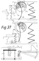
- a spring-loaded valve flap can also be opened temporarily (see Fig. 37).
- the opening of the adjustable spring-loaded valve inside the pot can now be prevented during the ascent of the cover plate and the possible opening for the air can be delayed to reduce suction.
- the central valve tappet is lifted out of its valve seat by the cover plate, but the ring of which it closes via a counter-taper.
- the bellows pot is lifted with the latter by pulling on the valve ring, the pulling action having an effect on the perforated pot via a membrane over a weaker adjustable compression spring.
- the weaker compression spring under the valve ring takes effect and lifts it into the upper taper of the valve tappet.
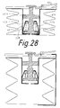
- a closed state only arises when the tension between the weaker compression spring and suction from below is balanced (see Fig. 28).
- the valve in the pot is kept closed by means of an electromagnet during the expansion of the bellows until it is fully developed.
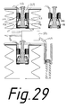
- the electromagnet receives the command to open the valve (or alternatively its function is stopped, see Fig. 29) via electrical contact closure (or power interruption) when the cover plate is at this high position.
- the ventilation valve in the pot can also be opened manually, regardless of the spring setting, for re-ventilation of the suction cup. If an electromagnet is used to actuate a ventilation valve, the skin in the suction bell can serve as a suction switch for the vacuum measurement, in which the skin tip level is reported in at least two different inevitable points of contact of the skin bell with housing parts and / or puncture tip or its carrier means in a kind of earth circuit .
- the electronic control center can stimulate the solenoid to open the valve in continuous or better in individual pulses when a skin level is reported;
- the skin contact that is still required is reported to the control center via the puncture tip itself, and possibly triggers an error message.
- the electromagnet is switched off until the measuring device reports success and the ventilation valve is closed.
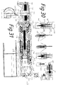
- the negative pressure is generated by glow wire heating of the housing surrounding the suction bell, a single double-barreled magnet can open both the valve to the suction bell and to the outside air (see Fig. 31).
- a horizontal piston pump is proposed for greater suction force with a smaller design.
- a single piston-cylinder pump with an oval shape is particularly suitable because a central pawl can be used to support drive springs for the piston (see Fig. 32).
- a telescopic sleeve slide system allows a reduction in overall length. From a collapsed state, the frame construction for the resilient skin support can also be extended with a single pulling movement and snap in this state (see Fig. 35, 36).
- an additional electromagnet is provided for unlocking the frame in a special case.
- the double-barreled magnet for the transverse puncture tip movement and for the ventilation must remain free for a fine functional play for the vacuum control (see Fig. 42).
- the resilient outer frame Before its lowering for puncture, the resilient outer frame must hold the central stamp against the strong compression spring for the piston, also the slide raster surrounding the punch is pulled out to trigger the piston.
- the outer frame can be constructed in a straight wall but also curved; the measuring device is preferably inserted into a rail between the bars of the frame; however, it can also be inserted laterally, for example into an elastic band on the opposite side of the punch opening (see Fig. 32).
- An intermediate cable can establish the electrical connection between the puncture device and measuring device shaft, provided the measuring device is not installed or attached (see Fig. 31).
- two cone screws are provided, on which a push button from the receptacle for the test strip under the suction cup roof finds resistance.
- the button can be inserted against a spring, sealed a distance, so that its second (separately and coupled depth-adjustable) cone bevel can be directed against the button if the first operation is unsuccessful.
- the skin gap or slit widening is accomplished in a variant in that the test strip - already shortened to a square plate - is moved in an upwardly convex arc in such a way that the puncture tip is moved a shorter distance than its fastening end on the test strip - possibly with a reversal of movement (see Fig. 34.40).
- the plunger can also be directed at a kink in the lower test strip and cause a deflection movement of the part of the puncture tip near the test strip, the actual tip being somewhat delayed and a shorter distance being moved (due to a lock for a fixed kink angle, see Fig. 41) ).
- the puncture tip can be delimited in a punctiform manner, which is favorable for minimal injury, but its shaft can be widened somewhat rectangularly towards the cutting direction for greater stability. (Before an electrolytic sharpening, the tip area is thus filled with a square material, see Fig.
- a holder can be provided for the test strip, which itself has a joint and the evasive movement lengthways the narrow side of the test strip (see Fig. 38, 39).
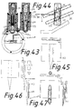
- Different pin cross-sections triangular, rectangular, octagonal
- Fig. 46 the shape variant of bending the puncture pin base out of the holding plate
- Fig. 45 a hollow channel
- Fig. 47 the addition of a cannula segment
- a test strip can not only be moved sideways along its narrow side, but also - especially after the jerk movement - also laterally and thus spread the wound or skin gap even better (see Fig. 44).
- the widening of the wound gap can be achieved in that the test strip is guided in an upwardly convex rail within its recording book, as a result of which the puncture tip and base move on other circular paths, the tip on a shorter or opposite to the base.
- an additional transverse displacement for example the combination of the method according to Pig.40 with that according to Pig.44 for widening the wound space, can also be useful, as well as the additional combination with test strip protrusions against the skin to fix the movement.
- the test strip can be swiveled with its receptacle along its narrow side or rotated eccentrically in the suction cup by means of a rotation segment.
- the packaging can also make use of a single split vaginal lamella, which encloses the test strip in a beak-like manner within an outer packaging envelope which can only be pulled off over the insertion area.
- the puncture tip itself can penetrate through a cross band of the lamella and wedge itself in by pushing the packaging sleeve deeper into the lamella against the test strip and to wedge it in place in order to promote the removal of the test strip from the shaft and the disposal (see Fig. 30 , Left).
- the function of the electromagnet (s) can be varied.
- a fork starting from a tube can act under magnetic influence on the outer flaps of a test strip - which serve to fix the skin - while a second electromagnet exerts the actual puncture ram function through the tube.
- Different magnetic segments or winding areas can also be supplied with current one after the other or with different strengths (see Fig. 30 right).
- the second electromagnet can also be chosen to be double-barreled and can be used with a release pull or push for the grid on the suction piston.
- the pump triggering can then be linked via the control center with the fulfillment of the condition of the earth fault by skin contact at the three switching points distributed over the edge of the suction cup.
- a pressure injector can also be connected to the puncturing device, for which a disposable gas pressure cartridge with a nozzle is presented as an example, which is operated with a gas-forming mixture.
- a disposable gas pressure cartridge with a nozzle is presented as an example, which is operated with a gas-forming mixture.
- permanent magnets and electromagnets can be used for transport and the necessary shapes can be rolled out (see Fig. 48). Intersecting transport lines can pick up the pins or sheets from the extrusion nozzle after cooling and separating the individual pieces until the plastic strip material for the test strip is rolled on.
- the example of a puncture device for multiple use without changing the test strip was added, which could be subjected to the same rules of negative pressure economy in use.
- the puncture pin is additionally tilted transversely to its impact movement, by kinking in the test strip, its guidance in a curved rail in the suction cup roof or simply by knocking against a swivel joint of the receptacle for the test strip and thus further away from the contaminating skin.
- the movement angle is determined (possibly changeable).
- Spreading of the skin can also be caused by non-moving or counter-moving extensions of the test strip, which extend to the skin in addition to the puncture tip, by at least two separate needles that have been driven apart and initially converge into a single tip, and are particularly effective transversely to the direction of the cut, for example, by the jaws engaging under the skin dent, which the Stretch out the skin area around the puncture tip.
- the area in which skin stains occur due to blood leakage from uninjured vessels can be kept smaller than in the case of strong suction over the entire diameter of the suction cup. It is not difficult to control the wedge that drives the jaws apart or the movement element via an electromagnet (see Fig.
- the device can also be used for blood collection, for example for blood cell counting and coagulation factor determination, the variant of a disposable suction bell with a cannula or puncture tip that can be swiveled around a joint is also proposed, as Gerhard Wagner already described for injection use as a small funnel after I wrote my registration in Kunststoff had withdrawn.
- a vacuum source for example a gas jet pump, which is operated with an acid-bicarbonate mixture or compressed gas cartridge
- a signal for re-ventilation can be obtained through blood circuit in the signal line (386); here for tearing off a gap in the wall. Since the device must be pocket-flat, it may be advantageous not to arrange the electromagnets in the suction bell, but in the suction space next to the suction bell.
- a dispenser can also be created for the very short test strips, similar to what BAYER has now released as a DEX for test strips without puncture tips. The dispenser is then brought into contact with the suction cup and the test strip is pressed upwards into its receptacle from below.
- the test strip with the puncture tip would only be returned to the dispenser in a second act after the skin puncture.
- the inclination of the puncture pin to widen the skin gap means that the length of the pin must be chosen longer, especially if the inclination has already taken place before the tip has destroyed blood capillaries.
- a puncture tip is moved transversely to the skin in the rotation process, it is expedient that it changes its height during its sector rotation, that is to say it moves on a spiral path. In this way, it is more likely to reach the network with the larger blood capillaries. Otherwise the tip would move at the same level with the skin.
- the swinging puncture pen moves radially to the top of the skin or skin dent.
- the object is achieved in that a steel tip, primarily made of VA steel, is used and the end portion of the test strip is incorporated or attached to it.
- the fine pencil which has to reach at least three millimeters below the surface of the skin in order to achieve a wider vascular network with its tip, can be obtained using an extrusion press, but can also be poured into molds. In the case of the advantageous production by means of an extrusion press, it is measured into corresponding pieces - for example by laser - (for example optically) and then divided.
- At the end of the test strip preferably in the middle area of the reactive test field with measuring reagents, it is either embedded in this test field, inserted between test fields if there are about two or more.
- the steel pin which should not exceed a millimeter in diameter in its widest extent penetrating the skin (a diameter of 0.5 millimeters and less is desirable), can also be glued to a finished, commercially available test strip.
- the elastic skin behind the puncture tip also gives way to a somewhat thicker pen, especially since there is no maximum skin tightening at the moment of penetration into the skin.
- the pen can also be attached to the test strip using an adhesive film.
- the tip can be sharpened according to the usual manufacturing method as in the manufacture of cannulas; but very advantageous is the electrolytic tip extraction in a bath with approx. 20% sulfuric acid and at a current of approx.
- the production line is arranged so that it dips into an acid bath on its transport route, at least the steel pin ends.
- the finished pin can also be pressed into a kind of hollow trough at the end of the test field, or it can be inserted into a tube provided, such as can be formed from plastic in the casting process.
- the method of pushing the puncture pin a short distance after the jerky movement, particularly when the skin is fixed in its vicinity can be combined with an inclined position of the pin, so as to locally exhaust the elasticity of the skin and open the wound gap.
- the puncture injury is intended to replace the skin injury or to outweigh it.
- Figure 1 shows a natural size in the middle right Horizontal or cross section through a puncture device.
- a pressure transmitter trigger in longitudinal section in three functional stages.
- To the right a longitudinal section through the suction cup, and at the bottom right by the bellows in the contracted state.
- Top right Longitudinal section details through the release mechanism for the Pressure sensor for the transverse movement of the puncture tip, far right Cross and longitudinal section detail through a variant.
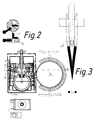
- Figure 2 relates to a device as in Fig.1. in which as a variant for further movement of the wound gap A special puncture tip via a braked plunger movement Device is provided.
- the 2: 1 scale there is a above Vertical section and including a cross-sectional detail along the Section line A - B of the lower cross section through the main part of the facility. All along the longitudinal detail below comes the slight eccentricity between the switching roller (58) and Compression spring for illustration.
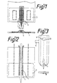
- Figure 3 shows in a scale of about 10: 1 in schematic Longitudinal section a special form of a test strip end with two Puncture needles at the end.
- FIG. 4 shows in natural size above the cross section of the device, which corresponds to that in FIG. 1 and is intended to serve as an orientation, at the top in two functional stages through longitudinal sections through the bellows. This is raised by a torsion spring using a wire bracket (not shown) (see Fig. 15 below).
- the cover plate (15) is extended on the left side by the hinge flap (65).
- the lower illustration shows the hinge flap after the slider (66) has been retracted from the knob of the hinge flap and folded up around its hinge to allow the hinged cover of the suction bell to pass by (see Fig. 5).
- the part of the cross section facing away from the suction cup is repeated and modified at the same time.
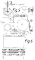
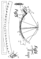
- FIG. 5 shows the hinged lid of a device according to FIG. 1 in a top view in natural size in a top view in a projection onto the floor plan of the suction bell in the middle left.
- To the right of the cross-sectional detail is a side view with a break open to show the position of the test strip (103) and the torsion spring (74) for the lid closure.
- the wedge from a spring plate bend on the release plate (53) is illustrated in the longitudinal section detail in the middle above.
- the cross-sectional detail (upper middle) corresponds to a top view of the cover plate (15).
- FIG. 6 shows variants of fastening a measuring device to the puncture device according to FIG. 1.
- a measuring device with a shaft (262) for inserting a carrier plate with the signal contacts is drawn.
- a shaft (262) for inserting a carrier plate with the signal contacts is drawn.
- FIG. 7 shows a cross-sectional detail above, a below Longitudinal detail through a device according to Fig.1 in natural Size. It should be the location and shape of the trigger plate (53) can be clarified. On the longitudinal detail is too recognize that a bridge of the trigger plate (53) below the Floor plate is passed through. Also the location of the Trigger plate outgoing spring tongue (55) clarified. All below the representation like that of the push button (222) - after one Trigger variant - outgoing blocking button (28) blocking in a hole the trigger plate (53) protrudes.
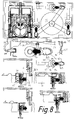
- FIG. 8 shows in natural size above a cross section through a device according to FIG. 1 when supplemented by a device for visual skin control and a variation of the trigger for the suction pump; it also shows the connection to the measuring device.
- the position of the spring tongue (55) which originates from the spring steel box frame (see Fig. 1), is shown again.
- longitudinal detail is given to explain the functional states of the release mechanism.
- FIG. 9 again shows natural longitudinal detail Size a variant of the trigger mechanism to Fig. 8 below with different functional stages.
- FIG. 10 shows the possibility of transferring the puncture tip movement transversely to the skin after being punctured by the impact of the plunger outside the suction cup on the test strip. and this both with a tip movement after the rotation (shown on the left) as well as after the oscillation (shown on the right).
- a tip movement after the rotation shown on the left
- an oscillation shown on the right
- FIG. 11 shows, on a scale of 2: 1 (with the steel pencil width much oversubscribed), two top views of a test strip (103) with a test field (104) and conduction paths with a puncture tip pierced into the skin (dash-dotted line).
- a side view To the right of this is a side view.
- the left top view corresponds to the stage after, the right one to that before the impact of the tappet tip.
- the steel pin is attached to a front central lamella of the test strip, is mostly behind the test field and moved to the right using the plunger (7).
- the top view of a test strip with the attached puncture tip for rotary use is shown at the top right. In the lower middle the variant of such a test strip. See note on page 160 below.
- FIG. 12 shows a longitudinal section overview to demonstrate a visual skin control on a scale of 1: 1.
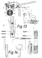
- FIG. 13 shows a suction cup with a device for puncture tip rotation at the top left in natural size, at the top in a longitudinal section details; including a top view of a perforated perforated plate (98), as can be inserted into the suction cup from below.
- the section line for the cross section runs along the line A - B of the longitudinal section.
- a longitudinal section detail of the left half of a suction cup is shown on a 2: 1 scale.
- test strip packaging variant on the far right, above before and below after being pushed together, above left with cross-sectional views along the cutting lines of the longitudinal section.
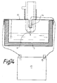
- FIG. 14 shows the end of a test strip (103) on a scale of about 10: 1 with a steel pin again, butting the Test strip is glued and first the dashed outline having. On the left is a side view, on the right a top view given.
- Figure 15 shows in the middle in natural size and light the cross-section shifted downwards through a puncture device according to the rotation principle.
- a longitudinal section reproduced when projecting the wire bracket for the Lifting the bellows with the cover plate), two above Bellows with parts of the cover plate as a longitudinal section detail.
- the longitudinal section at the top right shows a bellows in extended, which underneath in the compressed state and explains the suction regulation as in Fig. 4.
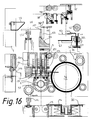
- FIG. 16 repeats the cross-section of FIG. 15 for an overview of the situation and explains some functional elements for the triggering functions thereof.
- the cross section of FIG. 15 is repeated for orientation.
- a longitudinal section detail is shown by the trigger according to FIG. 15 for the lateral cutting movement with the fixed grid sleeve (110).
- the left longitudinal section demonstrates the stage of locking, the right that unlocking.
- the cross-sectional detail above the left longitudinal section detail corresponds to the representation in the overall cross-section below.
- one of the two triggers (52) is shown in a longitudinal section detail under a cross section through the same, which are used to trigger the suction pump.
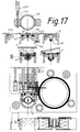
- Figure 17 shows the overall floor plan of Figure 15 (with the longitudinal section through the suction cup in natural size below) a cross-sectional detail through the rotor insert and End part of a slide bar in the scale 2: 1 suction cup (1) and including two further longitudinal section details through a suction cup with hinged lid in natural size (see Fig. 13, longitudinal section detail top left). Correspond to the row with the longitudinal section details a variant of the test strip attachment.
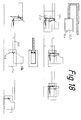
- Figure 18 shows schematically below a cross-sectional detail on the left (see overall cross section of Fig. 15) schematically three functional stages the push button operation in longitudinal sections.
- FIG. 19 represents a preferred solution to that already shown in FIG. 18 treated solution for a post-key. It will to the right of a longitudinal section is a cross section in different Functional stages and in an upper (hatched) and lower Variant shown.
- Figure 20 shows below on a scale of about 2: 1 with exaggeration a schematic section of the steel pin width Manufacturing chain for electrolytic sharpening and assembly of puncture tips on test strips in side view or (the Regarding electrolyte bath) in longitudinal section. A few chain links above and the interface for the test strip feed in scale 10: 1 above in a side view, below in a cross section.
- FIG. 21 shows a solution for the puncture tip movement transversely to the skin in a cross section at the top and in a longitudinal section at a scale of 2: 1, in which electromagnets are used within the suction cup.
- An example of the vibration method is given on the left, one for rotation on the right.
- Below - with omission of the suction cup - a cross-sectional detail with a variant of the magnet function design is given, namely in the excited state of both magnets.
- the two double profile line pairs represent a pulse sequence of the magnets
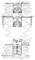
- Figure 22 shows two examples on a scale of 2: 1 in longitudinal section for suction strength control using valves in the pot of the Bellows, which is also the re-ventilation of the suction bell can serve.
- the first example above shows the bellows in two stages of expansion.
- FIG. 23 is a supplement to the equipment variant according to FIG. 1, based on the oscillation principle for the puncture tip. It illustrates how, after the tappet (7) impacts the test strip inside the suction bell (neither of which is shown), the tappet can be moved more slowly to widen the skin gap.
- the adjusting screw (54) can be seen on the schematic longitudinal section detail in natural size above. The cross-sectional detail below shows the attachment of the axis of rotation (19) for the flap in the base plate (16) and the window gap for the sliding distance of the sliding frame.
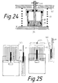
- FIG. 24 schematically shows a longitudinal section through a Cylinder-piston pump with flow option for the cover plate Suction regulation.
- FIG. 25 shows a top view on the left at a scale of about 10: 1 and on the right a longitudinal section through the middle of the top view on a test strip with attached puncture tip (black).
- the vertical section on the far left shows one over the puncture tip area for removing the test strip with the capillary (174) advanced foil sheath.
- On the right the stage after use (the Blood in the capillaries is not shown) and after insertion the foil sheath. Above a cross-section along the cutting line A - B.
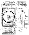
- FIG. 26 is based on FIG. 7 and provides a further solution for triggering the suction in connection with the problem of tensioning the strong compression spring (not shown) for the bellows.
- a cross section is shown above, including a longitudinal section and on the right a longitudinal section detail from the edge zone of the cross section with a schematic representation of the release mechanism by means of the spring steel box frame.
- the longitudinal section detail through the lock button for the release plate movement.
- the function of the spring tongue (55) in pairs is made understandable on the longitudinal section.
- the lower one of the longitudinal section details on the right shows the condition when the large compression spring is tightened after lowering the cover plate (15).
- FIG. 27 largely corresponds in its upper cross-sectional representation in natural size to FIG. 26.
- a vertical section detail using the re-key on the right the bend of the trigger plate, on the far right the locking grid for lowering the cover plate within the telescopic tubes, with a cross pin recognizable in cross-section on the left.
- a longitudinal section with the measuring device symbolically attached as a rectangle and dash-dotted line connections to the puncture device.
- the position of the tappet (7) to the right of it the vertical section through the regroup button and on the far right, a vertical section detail to illustrate the suspension of the spring steel box frame.
- FIG. 28 is structurally closely based on FIG. 22. Again, these are two longitudinal sections of different functional phases a pressure control valve inside the pot Bellows (64) as a suction pump in 2: 1 scale.
- FIG. 29 also shows two functional stages in the Longitudinal section, but in natural size a device for solving the same problem by means of an electro-immersion magnet (144).
- Figure 30 deals with the packaging problem of a test strip with puncture tip similar to Fig. 11 and 13.
- the scale is 4: 1.
- the puncture tip is strong again oversubscribed.
- On the left a top view, on the right a longitudinal section.
- a longitudinal section and a top view follow to the right a solution variant, on the far right a clarification making sure the puncture tip is in a cross bar of the packaging film.
- At the top right a special one Longitudinal section of an electromagnet and the diagram of its power supply.
- FIG. 31 shows an example of a puncture device in which heating wires are used as a suction pump.
- the representation is made in longitudinal section on a scale of 2: 1.
- To the right of this is the push-on sleeve for a measuring device.
- On the right above the longitudinal section is the small vertical section detail of the outer button.
- FIG. 32 shows a cross or horizontal section at the top including a device in a longitudinal section on a scale of 2: 1 using an oval piston-cylinder pump. Is below on a 4: 1 scale, the cross section through a re-cutting device clarifies. To the right of this is a vertical section with the slide on Measuring device and on the far right the top view of a connecting cable, each in 2: 1 scale.
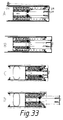
- Figure 33 gives four in cross-sectional detail on a scale of 1: 1 Functional stages A - D of a device according to FIG. 32 again.
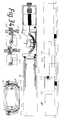
- FIG. 34 shows the schematic side view above and below it a longitudinal section through a device similar to that described in FIGS. 32 and 33.
- the cylinder or the base plate were shortened considerably by a sliding construction.
- the curved rail guide in the suction cup demonstrates a mechanism for opening the wound splitter.
- the locking of the pull-out rail against the spring tension in the piston is explained at the bottom left in two functional stages, in each case on the left in a vertical section and on the right in a longitudinal section along the outer edge of the puncture device.
- the cylinder On a vertical section on the right, with the omission of the tension spring and the piston, the cylinder is shown as the base plate (16), which is held by a kind of spring steel box frame.
- FIG. 35 again shows the variant of FIG. 2: 1 Device according to Fig. 32,33 in the manner as shown in Fig. 34. They are cross-sectional details in two different ways Functional stages and in different configurations of the suction cup area.
- FIG. 36 again gives an overall cross section (top) and a side view along the side wall of a device according to the Fig. 33-35 with a further variation of the locking of the Frame parts.
- FIG. 37 shows schematically on a scale of approximately 3: 1 in longitudinal section a triggering device for the plunger (7) of a mechanical device approximately according to FIG. 27.
- the detail at the bottom left in a vertical section shows how the set screws (286) via the cross pin (black) not only restrict the amount of movement in the sector slot of the wheel segment (284) but also limit the height movement of the cover plate (15) by means of a pair of cable pulls (288).
- the negative pressure is also regulated via a valve with a cable.
- On the right a lever variant for the trigger of the suction pump in two functional stages.
- FIG. 38 shows schematically in longitudinal section on a scale of 2: 1 a test strip (103) with a puncture tip in one swiveling receptacle.
- Figure 39 shows the possibility on a scale of 2: 1 in cross section on, a plunger (7) on an eccentric under the suction cup roof disc (289) rotatable about an axis - for example on a segment notch - let it work.
- Figure 40 shows schematically on a scale of 2: 1 in longitudinal section the possibility of guiding the receptacle (231) with the test strip along one upwards convex under the suction cup roof curved rail (237) range and direction of movement between the puncture tip and the shaft base.
- FIG. 41 shows a schematic longitudinal section on a scale 2: 1 a solution in which the test strip the joint (290) has around which it can be bent.
- the kink angle is, for example thereby limited and fixed, so that again the puncture pin is inclined.
- FIG. 42 shows a schematic longitudinal section through the Suction cup (1) on a scale of about 1: 1 is the preferred solution a control of the electromagnet (144) for the seat valve (208) via the earth contacts marked as three rings within the Suction cup.
- FIG. 43 shows a schematic longitudinal section on a scale 2: 1 through a suction cup from a puncture device with the Possibility to connect an injector, here a single-use injector with propellant charge.
- FIG. 44 shows schematically in a cross section on the scale of about 4: 1 a possibility of the puncture tip obliquely to Direction of action of the plunger (7) to widen the skin gap to move it.
- FIG. 45 shows a cross section at the top and a cross section at the bottom Top view on a scale of about 4: 1 with a test strip (103) welded steel foil plate and cavity in a hollow channel towards the puncture tip.
- FIG. 46 shows a top view and to the right of it in one Vertical section in 4: 1 scale a puncture tip variant, in which to stabilize against the impact movement of the puncture tip shaft at the point of exit from the end of the test strip is arched.
- FIG. 47 shows a longitudinal section on the left and a vertical section on the right on a 4: 1 scale, welding or gluing of a cannula segment on the test strip (103) with the test field (104).
- FIG. 48 shows additional details on a scale of about 4: 1 to the manufacturing process of the test strip with a puncture tip.
- a longitudinal section through a hexagonal, rotatable Drum with electromagnet.
- a transport link with permanent magnet for pin fixation including small cross-sectional detail through the hollow channel with pin.
- the cross section along section line A - B Left in the middle to the bottom a pair of rollers over an extrusion die for steel, to the right two reels to demonstrate Profiles for the roll surface with small cross sections from the pin groove in between.
- Figure 49 shows in natural size above and in the middle in Longitudinal section and below in cross section at the level of section line A - B of the middle longitudinal section the example of a puncture device without the need to change test strips manually.
- FIG. 50 shows three longitudinal sections through the puncture device along the section line C - D of the cross section in Fig. 49 below three functional stages A - C.
- Stage A corresponds to that in the upper longitudinal section of Fig. 49, stage C one in the lower longitudinal section in Fig. 49 under skin suction.
- FIG. 51 shows a longitudinal section on the right at a scale of 2: 1 through the cap (495) with one of the gear pairs for the test strip transport. To the left of it a vertical section detail the shaft for the mechanics of the test strip transport.
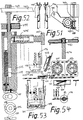
- FIG. 52 shows a 2: 1 scale puncture stylus (175) with special equipment for the rotational movement of a cutting tip in a test field that can be rotated through a small sector angle within a test strip band in a longitudinal section.
- Figure 53 gives 2: 1 details about a coupling a test field at the end of the puncture pen in a vertical and below in a longitudinal section (based on the longitudinal section of Fig. 52).
- Figure 54 shows a scale of 2: 1 again in longitudinal section above a representation of the locking of a pin (476, see Fig.50) with the bottom wall of the glucometer (176). Below this is a top view of a piece of test strip on a 2: 1 scale. The side edge perforations of the test strip (103) can be seen. Between the middle plan view in FIG. 54 and between the illustrations in FIG. 53, two test strip ends are shown, which are joined together by means of the hooks (504, 505). A longitudinal section below shows a cutting tip which, under tension, is bent to the left against one of the legs adjacent to the upper wall cladding of a test field. At the very bottom, in longitudinal section, a piece of test strips on a 2: 1 scale to show an alternative cut. On the left, two parallel wedge tappets are pressed against their test strips to apply test strips to their compression springs (not shown). To the right of this is a magnetic coil for the cutting movement of the cutting tip across the test strip transport.
- Figure 55 shows on the left in a schematic longitudinal section a suction bell (1) on a scale of 2: 1 a device similar to that the Fig.40 with the curved rail (237) for the guide the receptacle (231).
- Figure 56 shows a side view on a scale of 2: 1, with stronger Exaggeration of the width of the puncture pen, an example of a test strip with a puncture tip, as used for both Movement of the puncture tip after the swinging as well as after the Rotation principle can be applied.
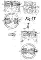
- FIG. 57 shows the side view of a test strip at the top, which laterally has slots in which the wire ring (317) It is introduced that extends down to the skin with its three supports.
- FIG. 58 shows, approximately on a scale of 1.5: 1, schematically in longitudinal sections a device for the semi-automatic test strip change as a preliminary stage of a fully automatic machine.
- the slide box (319) with the sliding cover is withdrawn and the pipe socket (324) is inserted from below into the suction cup until a collar stops.
- FIG. 59 shows a longitudinal section at the top left one Cross section through the detail of a suction cup (1) at the level of Diving magnets in 2: 1 scale.
- the detail on the right is on the right Dip solenoids for valve actuation in 4: 1 scale Longitudinal section drawn out.
- the bellows serving as a suction pump completely and concentrically enclosing the suction bell (1).
- the left half corresponds to the stage of tensioning the strong compression spring (70) while reducing the bellows (46), while the left half shows the state after the compression spring has relaxed while expanding the bellows.
- the lower longitudinal cuts broken open to the right of the middle, the upper corresponds to a suction position, the lower corresponds to the state of the bellows compression.
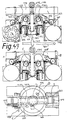
- Figure 61 shows a cross section in natural size above by a puncture device according to Fig. 60 at the level of the electromagnets in cross section.
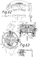
- Figure 62 shows one of the four segments in natural size of the release ring (344) according to Fig. 61 above in cross section. Below on the left in longitudinal section the detail of a chain of the segments. The side view in Rolling up a spring back for the release ring (above in cross section, when tilting the, on the right the longitudinal section detail of one Spring tongue.
- FIG. 63 shows a variant of the equipment of a suction bell for a puncture device on the left in cross section and on the right in longitudinal section on a scale of 2: 1.
- the longitudinal section shows how a cone tip on the left through a hole in the cover of the sheet metal ring (350) the raised skin reached; it serves as an electrical touch switch.
- a fragment of a claw is shown at the bottom left, which is useful when inserting and attaching the magnetic equipment to the suction cup.
- magnets here one
- FIG. 64 shows a cross section in natural size a puncture device similar to that in Fig. 60 to 63, in which but the more pocket-friendly rectangular shape was chosen.
- the suction cup with the magnet and puncture equipment is located centrally within the box-shaped bellows (46), which the Compression spring (70) surrounds.
- FIG. 65 shows a cross section on a scale of 1: 2 Setup as in Fig. 64, however, the suction cup is of two square bellows flanked by a respective compression spring. (Right is as an alternative through circles within the fold -balges the use of several round compression springs in series indicated).
- FIG. 66 shows a sketch on a scale of 1: 2, the combination of a puncture device with a suction bell inside the bellows, an electromagnet and battery and a supply device in the ring housing with a commercially available measuring device (for example a glucometer).
- a commercially available measuring device for example a glucometer.
- the detail at the bottom right outlines a cross section of an electromagnet that can be mounted as a rotor in the center of a suction cup and whose central axis carries the receptacle with the test strip (shown in dashed lines).
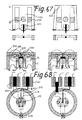
- FIG. 67 shows a cross-section at the top in a top view in the height of the section line A - B in the scale 3: 1 - at severe exaggeration of the puncture tip - the variant of a Test strip according to Fig. 11 with side flaps in the left the drawn stage are pushed apart by wedges, to widen the wound gap.
- FIG. 68 shows a longitudinal cross-section at the top and a cross-section at the bottom the detail of a suction cup with a special device for spreading the wound gap (in the case of severe exaggeration of the puncture tip) about 1.5: 1 on the left in the stage and right in the stage after the wound gap spread.
- Figure 69 shows a natural-sized longitudinal section Puncture device for multiple use also with different People again. A cross section under the suction cup by the same.
- FIG. 70 schematically shows a suction bell (1) in longitudinal section. for single use with surrounding vacuum storage (383), the industrial is evacuated. The tension of against the wearer of the Capillary-directed spring arch is through the electrical wires (384) held.
- FIG. 71 shows a longitudinal section through the lower part of a test strip at a scale of 1:15 that already sharpened Steel pin (1) made of a kind of tube (2) Plastic inserted or in the plastic mold when embedding the reaction fields got into such a tube.
- Cross section shows the variant of a hollow channel with protruding Edges behind which the pen is held.
- FIG. 72 corresponds to that of FIGS is also shown in longitudinal section.
- the plastic tube (2) continues in this case. It became a second one from above smaller pin introduced as a contact pin.
- For power line can there is an electrolyte liquid between the pin end (1) and the upper contact pin are located.
- FIG. 73 shows a commercially available test strip in the view from the back on a scale of about 4: 1, the Thickness (width) of the steel pin (1) was still greatly exaggerated. This is glued to the back of the test strip so that the tip area protrudes above the test strip. For fixing serves to reinforce the film (7), as on the cross section below is recognizable.
- the power supply for the electrolyte bath takes place via a line to the metal foil spot (8).
- FIG. 74 shows a basic arrangement for the manufacture of tips a steel pin (1).
- the tub (9) is up to a predetermined height filled with 20% sulfuric acid.
- Figure 75 shows a scale of about 1: 4 at the top and a roughly natural size at the bottom - in reality, of course (apart from the even smaller steel pins) it is even more generously dimensioned.
- a manufacturing process by sharpening the steel tip in the acid bath which is shown below as a natural cutout.
- FIG. 76 shows a longitudinal section through the end of a test strip on a scale of about 4: 1, a pointed steel pin (1), which is inserted through a hole across the course of the test strip (the surrounding test field has been omitted).
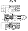
- FIG. 77 shows a vertical section at the top on a scale of 2: 1 of a medicament injector with suction bell (7), gas jet pump (24), battery (29) and control center (17) in natural size.
- the puncture agent equipment for diagnostic purposes corresponds to that of Fig. 59.
- the position of the screw thread for the propellant cartridge is indicated in the upper longitudinal section, in the lower one the equipment with the electromagnets.
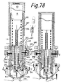
- FIG. 78 shows a longitudinal section on a scale of 1: 1 of a puncture device with a puncture tip on a test strip without the use of a suction cup. The phase before and the phase during the puncture are shown on the left.
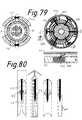
- FIG. 79 shows cross sections along the section lines A - B and A - C of the longitudinal section of FIG. 78, and at the bottom right a lateral roll-up as a detail of an adjustment mechanism for the length of the transverse movement of the pin.
- FIG. 80 shows a test strip on the left in packaging, on the right after use in longitudinal and vertical section, scale 2: 1.
- FIG. 81 repeats FIG. 77 in longitudinal section and supplements its description.
- the lower longitudinal section represents a variant which is equipped with magnets for an additional rotation and a lowering of the test strip in addition to its swiveling according to the oscillation principle.
- To the right of this is a 4: 1 scale test strip with a bayonet curvature of the puncture pen.
- FIG. 1 shows in natural size in the center right a horizontal or cross section through a puncture device. Slightly enlarged in the top right, the detail of a pressure sensor trigger in longitudinal section in three functional stages. At the bottom right, a schematic longitudinal section through the suction bell on the left and through the bellows of the suction pump on the right. Top left two schematic representations of the power transmission and control slide in two functional stages. Below, to the left of the suction bell in cross section, a longitudinal section through the suction bell, including one through the bellows in an extended state. Starting with the cross section, it can be seen that the plunger (7) has been pushed through the sealing ring (5) in the suction cup wall and with its rounded tip lies against the test strip (103).
- the adjustment screw (54) for limiting the plunger movement near its obstacle, the flap (18) that extends down onto the plunger in front of a portion of the adjustment screw.
- the flap - it is shown in dashed lines - is rotatable about the paired pin (19), which is attached symmetrically to the housing block of the base plate (16).
- the sliding frame (20) is mounted along the side walls of the housing block, the ends of which rest against the two compression springs (30), which are supported on the opposite side against the support plates (21) on the housing block. Starting from the sliding frame, a pipe sleeve is directed against the adjusting screw (22) that can be screwed onto the plunger.
- the knurled screw (23) following on the tappet has its abutment in the buffer (26), the wedge flank and springback of the tappet end which is illustrated on the left along the longitudinal section by means of a compression spring, and which in this case is symmetrically arranged in pairs.
- the holding arm for the locking button (28, see Fig. 7 below), which engages in a hole in the trigger plate (53), arises from the pushbutton (222) for a re-cut after unsuccessful use via the adjusting screw (54).
- the paired guide pin (31) is attached to the housing block and runs in a vertical guide slot of the push button.
- the pin (33) which starts from the sliding frame (20) and in which corresponding window cutouts for the guide pin (31) and the axle pin (19) are provided for its sliding movement, is guided in the oblique slot of the plate of the push button.
- the upper longitudinal section shows the stage in which the sliding frame was moved to the left by lowering the push button by means of the oblique slot.
- the two symmetrically arranged pushbuttons are connected to one another via a bridge.
- the auxiliary spring (34) under the pushbutton and supported against the base or housing plate was tensioned.
- the flap (18) had already been folded upwards with the cover lift around the axle pin by means of the pull string ((36, Fig. 4 center).
- the functional changes to the state of the push button lift can be seen from the comparison with the longitudinal section below
- the position of the tappet (7) with the sealing ring (5) and the compression springs (30) can be seen in the longitudinal section through the suction bell below.
- the mouth of the suction channel (32, see Fig. 7) was also outlined.
- the hinged cover (206) is drawn on the longitudinal section on the left and seals the interior of the suction cup against the sealing ring (38). It is suspended around the paired hinge joint (39) towards the suction cup (see Fig. 5, longitudinal detail on the top right).
- the test strip is symbolically replaced by a line to demonstrate that it pushes back on the plunger (7) when the lid is closed works.
- the sleeve (41) is pushed onto the end of the plunger, which expediently does not have a square diameter - approximately oval - the eccentric end plate of which has a knob directed against the test strip (103), shifting the stop point for the pressure transmitter downwards.
- the shaft (62) at the bottom of the lid center for attaching the test strip shows the lead contacts and lead ends for signal transmission.
- a return spring 43, see Fig. 4 center left
- the paired compression spring (30) is tensioned by means of the paired wedge slide (37), which is pushed off by a slide hook (44) extending from the cover plate (15, longitudinal section detail at the top right).
- the longitudinal section on the top right shows the stage before this displacement, on the right next to that of the complete displacement, blocking the wedge slide and thus the ram back movement.
- the tension spring (218) attached to the cover plate is tensioned from its end and the slide hook is held on the elastic tongue at the end of the wedge slide (37). Since the slide hook - on a pin (not shown) in a groove guide - cannot leave the sliding sleeve that extends from the cover plate, the strong compression spring (70) around the bellows (46) lifts the cover plate when the cover plate is lifted elastic tongue through the hook of the pusher hook, after which it shoots up under the action of the tension spring and releases the movement of the wedge pusher (on the far right in detail).
- the detail of the bellows (46) as a suction pump is shown in the longitudinal section at the bottom left and right, on the left in the state of the bellows expansion by the compression spring (70), on the right in the compressed state.
- the sleeve system is simplified to line width.
- the pot (41) covers the bellows (46) tightly at the top and has a central grommet with an external thread at the bottom. In the latter, the screw cap (45) with an internal thread is screwed in, the movement of which is inhibited by a pin on the edge of the tub after a sliding distance inside the centrally drilled trough of the cover plate (15).
- the wedge slider (37) can have a fork for a pin end with a (semi-) spherical or conical cross-section and a (wedge) bevel for a ledge hook (cross and longitudinal section details at the top right)
- Figure 2 relates to a device as in Fig.1. in which as a variant for further movement of the puncture tip to block the wound gap a special device via a braked tappet movement is provided.
- 1 scale there is a vertical section above and below a cross-sectional detail along the cutting line A - B of the lower cross section through the main part of the device shown.
- the lever arm (58) is with its crossbar in the end by a compression spring with counter bearing on pins from the Housing block of the base plate (16) in the opposite direction to the plunger movement held and cushioned.
- the longer angle arm on the other At the end, the knurled screw is used for the re-cut to the stop.
- the switching roller (59) which can be freely rotated around the lever arm, is in stored in a trough of the device block and has a segment slot on. The latter leaves a short crossbar on the lever arm if the switching roller is activated by the push button (222) pin engaging in an edge notch of the control roller is rotated during the downward movement of the push button.
- the Knurled screw that changes after the sudden recutting movement leaning against the angle arm can now be damped by the described Compression spring for the lever arm a little further towards the suction cup move.
- On the longitudinal detail comes at the very bottom the slight eccentricity between the switching roller (58) and the compression spring for illustration.
- the dashed ring around the suction bell corresponds the possibility of a leaf spring, which is then expedient is eccentrically supported against the knurled screw and can alternatively dampen their final movement.
- Figure 3 shows in a scale of about 10: 1 in schematic Longitudinal section a special form of a test strip end with two Puncture needles at the end. These puncture needles are set in two Slats of this test strip continue, into which they are in the tips are welded converging. A central wedge is made after the Puncture of the double tip into the skin with height fixation of the test strip lamellae (symbolized by the two rectangles) between the puncture needles and one (dashed shown) Bridge connection between the slats blown up.
- the cross section below along the section line A - B of the longitudinal section shows the skin gap formation for the blood leakage on the test field or fields (104), which is mounted here in the wedge (but can also be placed in the slats).
- FIG. 4 shows in natural size above the cross section of the device, which corresponds to that in FIG. 1 and is intended to serve as an orientation, at the top in two functional stages through longitudinal sections through the bellows. This is raised by a torsion spring using a wire bracket (not shown) (see Fig. 15 below).
- the suction strength is controlled by turning the screw bolt (63, which engages with a hexagon in a screw nut whose external thread engages in the internal thread of the socket grommet, which is firmly connected to the pot as the cover of the bellows. Rounded edges leave the hexagon of the bolt securely penetrate the hexagon of the screw nut
- the free movement for lifting the cover plate is set larger in the upper illustration than in the lower one.
- one of the three cover pins (213) within the support sleeve (64) attached to the base plate is slightly reduced from a rear plane and slightly reduced.
- the latter has a slot for the passage of the trigger plate (53, see Fig. 7), which moves to the left, releasing the movement of the cover pin.
- the cover plate (15) is extended by the hinge flap (65), the pointed end bar of which extends down onto the wedge slide (37, see Fig. 1) - parallel to the end beam directly at the end of the cover plate for the parallel sliding wedge.
- the lower illustration shows the hinge flap after the slider (66) has been retracted from the knob of the hinge flap and folded up around its hinge to allow the hinged cover of the suction bell to pass by (see Fig. 5).
- the trigger is guided centrally on a pin of the housing plate (16).
- a telescopic rod (69) is inserted through a hole in the latter and has at the end a leaf spring arch which is directed against a nose on the trigger (52, the trigger being secured against rotation.
- the connecting web (71) connects the rod ends of two such telescopic rods below of the bellows (721, see cross section below) If the telescopic linkage is lifted to the maximum by pressure from the connecting web, the paired trigger is raised and the release plate is shifted to the right, whereby the lid pin movement is released (longitudinal section detail on the top right) its leaf spring overtakes the nose on the trigger, the visual skin check can now be carried out analogously to Fig. 12. Below the longitudinal section detail, the cross-sections through the trigger and telescopic linkage pushed together.
- FIG. 5 shows the hinged lid of a device according to FIG. 1 in a top view in natural size in a top view in a projection onto the floor plan of the suction bell in the middle left.
- the transverse pair of axle pins (71) with the cover flaps - here slightly shifted inwards according to the interior variant Fig. 4 center left - frames the band of signal lines (72) - here three - from the shaft (62) with its clamping springs, which is oversized in width, to keep the leads on the end of the test strip in contact with the signal leads.
- To the right of the cross-sectional detail is a side view with an opening to show the position of the test strip (103) and the torsion spring (74) for the lid closure.
- the wedge from a spring plate bend on the release plate (53) in the longitudinal section detail in the middle above illustrates a variant of the suction release by displacing this wedge to the right from a start button (symbolized as a line).
- the cross-sectional detail (upper middle) corresponds to a top view of the cover plate (15).
- the hinge flap (65) is locked by moving the slide (66) to the left until its edge abuts its knob.
- the left-hand thrust takes place through the correspondingly mounted leaf spring (76), which is, however, more conveniently arranged under the cover plate and there against a pin at the end of the slide within a slot guide in the cover plate, whereby the knob described on the hinge flap can be omitted.
- the slide is guided in an internal slot.
- FIG. 6 shows variants of fastening a measuring device to the puncture device according to FIG. 1.
- a measuring device with a shaft (262) for inserting a carrier lamella with the signal contacts is drawn, which is inserted with the pair of fastening rods into a bar on the base plate (16) and can be swung under it.
- These include two detailed variants of detachable frame connections with the base plate (16).
- springs attached to the measuring device or its mounting frame snap into niches with undercuts at the edges.
- the fastening rods of the measuring device are pressed from the base plate into a lateral undercut of the joint niche by means of a leaf spring.
- the measuring device is first moved to the left against the leaf spring to release the connection.
- the detail in the middle shows how the undercut can be replaced by a spring plate cover, which also allows the resilient ski tongue for the fastening rods to protrude into the niche (the fastening rods were not shown here).
- FIG. 7 shows a cross-sectional detail at the top, a longitudinal-section detail below through a device according to FIG. 1 in natural size.
- the position and shape of the trigger plate (53) should be clarified. This is divided into several segments, in order to create freedom of movement in front of the functional elements crossing their course. In places where there is a particular shortage of space in the horizontal, the plate is reinforced by bending upwards. (Such an example offers the connection between the grid segment in engagement within the right lid pin and a support sleeve (64) behind the telescopic linkage (69) to the trigger (52, see Fig. 4 center right), which the trigger plate at his Raised to the left.
- the pair of spring tongues (55) running on both sides in the wall niches of the base plate ensure that the trigger plate springs back to the right into the locking position.
- the sealing ring (77) - it can be an elongated O-ring - frames the suction channel (32) which is partly formed by a groove on the underside of the base plate on the route between the bellows center and the suction cup wall. It is pressed against the base plate by the base plate (78). (The mounting screws for the floor panel have been omitted.) On the longitudinal section detail it can be seen that a bridge of the release plate (53) is passed below the floor panel. The position of the spring tongue (55) extending from the trigger plate within the niche in the base plate (dashed rectangle) is made clear once again.
- the pushbutton the raising of which is not supported by the auxiliary spring (34, see Fig. 1) in this case, must be pulled up by hand in this case immediately before the connecting bar (71, see Fig. 4) is put on the trigger to release the movement of the trigger plate.
- FIG. 8 shows in natural size above a cross section through a device according to FIG. 1 when supplemented by a device for visual skin control and a variation of the trigger for the suction pump; it also shows the connection to the measuring device, which is made mechanically by means of the pair of fastening rods (56) and electrically by means of the signal lines (72), which leads from the shaft under the hinged cover into the support plate (209). The latter is inserted into the shaft (262) of the measuring device instead of a test strip.
- the two telescopic rails are held together by the elliptical sheath segment (69).
- the guide grooves for the pins to limit the extension length in the longitudinal slots must therefore be rotated by 90 degrees.
- a mutual dovetail or meander jointing of the telescopic rails (269) would also be advantageous.
- the sleeve of the trigger (52) carries two cross pins opposite one another, a lower (88) which is raised by the front or right wedge slide flank (85) and an upper or left (84) which by the rear or left wedge slide flank (86) is lowered.
- a cover plate pin or here by a cover edge
- the spring force being stored in an arc (cf. Fig. 9, top right).
- this is only the case insofar as the right wedge slide surface is pushed up by the lower cross pin ((88) on the right wedge slide flank by lifting with the trigger in the final phase of lifting the telescopic linkage (69). If the lower pin leaves the right-hand wedge gate flank, overtaking it in a slot at the top (or at its top edge), the force stored in the spring arch can take effect and push the trigger (52) downwards by means of the left wedge gate valve.
- the schematic representation of the trigger mechanism according to Figure 8 in Figure 9 above shows the mode of operation and stages next to one Longitudinal section through the trigger (52) and a view of the wedge or spring slide in the longitudinal section detail even more clearly.
- the cover plate pin (the cover plate was omitted) the wedge of the wedge or spring slide (87) still not ousted.
- the trigger is lowered.
- the grid body (89) is in the locking position in relation to the lower telescopic rail (not shown).
- the cover plate pin In the top right stage, the cover plate pin is lowered and has displaced the wedge or spring slide on the left wedge end to the right.
- the shortening of the spring causes a build-up of force in the deformed spring arch. since at the same time the trigger (52) was raised so far that its lower right transverse pin displaced the front wedge flank of the wedge or spring slide to the left by lifting the (not shown) telescopic linkage from below.
- the release variant shown in the middle in longitudinal section details uses the release (52) to lock the release (sector rotation).
- the grid trough in the trigger is not an annular groove here but a directional bore (91).
- the wedge or spring slide (87) is mounted deeper in the base plate (16) and, when shifted to the right, causes the wedge flank to act in pairs on the lower edge of the sleeve of the release (stage on the right).
- the shift to the right again takes place via the action of a cover plate pin perpendicular to the wedge end of the wedge or spring slide.
- the bore of the grid (91) is rotated away from the axis of the grid body, the train for the grid in a different radial position can pass through the grid body when the telescopic linkage is pulled, so that it is not triggered.
- the bore is turned back into the position just above the grid body, so that finally at maximum Raising the telescopic linkage, which lies below the possibility of lifting the trigger, triggered the grid body from the telescopic rails.
- the end rod of the telescopic rod can be rotated in the foot part of the connecting web (71).
- FIG. 10 shows the possibility of transferring the puncture tip movement transversely to the skin after puncturing the skin by impacting the plunger outside the suction cup on the test strip, both with a tip movement according to the rotation (shown on the left) and after the oscillation method (shown on the right).
- the round locating pin rotates with the shaft (62) for the introduction of the test strip (103) in the roof area of the suction cup (1) within the sealing ring (5).
- the plunger (7) - here also a counter plunger for a re-cutting movement - abuts a segment with an internal thread, which is connected to a pin by a bridge, so that during the sector movement, the plunger rotates with a change in height of the puncture tip , wherein the steel pin runs the non-sharpened distance parallel to the test strip (103) and is glued to it.
- the further design such as limiting the angle of rotation or subsequent movement to widen the skin gap, results from the other descriptions.
- the top of the skin is shown in dash-dotted lines and is dented centrally by the test strip.
- the details on the right are longitudinal cuts if the cutting direction deviates by 90 degrees.
- the shaft into which the test strip is inserted can be pivoted inside the suction cup in the suction cup wall by the paired sealing ring (5) by means of lateral levers outside the suction cup by means of plungers (7) or counter-plungers. In the lower cut, the top of the skin is again drawn with dash-dotted lines.
- FIG. 11 shows, on a scale of 2: 1 (with the steel pencil width much oversubscribed), two top views of a test strip (103) with a test field (104) and conduction paths with a puncture tip pierced into the skin (dash-dotted line).
- a side view To the right of this is a side view.
- the left top view corresponds to the stage, the right one to that before the tappet impact.
- the steel pin is attached to a front middle lamella of the test strip, is mostly behind the test field and moved to the right by means of the plunger (7).
- the rear test strip lamella, the front one framing laterally, is more rigid or at least largely independent of the pivoting movement of the lamella with the puncture tip.
- the lower figure shows the top view of a solution with only a single test strip lamella, which is split by deep incisions along the central strip with the puncture tip and test field, the central strip remaining movable.
- the ends of the side lamella parts, which are set up against the skin, are pointed more triangularly.
- the top view of a test strip with the attached puncture tip for rotary use is shown at the top right.
- the puncture tip is mounted eccentrically. in the center is enough an intensification of the comparatively rigid test strip lamella next to the steel pencil right down to the skin (shown in dash-dot lines).
- FIG. 12 gives a more schematized longitudinal section overview for demonstrating a visual skin control on a scale of 1: 1.
- the telescopic linkage (69) below and around the bellows (46) compressed against its compression spring is pulled out all the way down and was placed on the skin.
- the bracket on the spring box frame is regulated by means of the spring tongues (55) on the adjusting screws (81) with its contour above that of the base plate (16) of the housing. Since the current loop (dash-dotted lines on the right) is closed by contacting conductive parts of the telescopic rod (shown schematically as a hook) in this end position, current from the battery (83) can supply the three light sources (17) electrically, only two of which are open a central area of skin is shown. The central skin area corresponds to the later puncture site.
- the spring bleaching box frame is now lowered against the skin on the holding bracket (79) and then the base plate and the suction bell and thereby the suction pump are triggered.
- FIG. 13 shows a suction cup with a device for puncture tip rotation at the top left in natural size, at the top in a longitudinal section details; including a top view of a perforated perforated plate (98), as can be inserted into the suction cup from below.
- the section line for the cross section runs along the line A - B of the longitudinal section.
- the rotor insert (97) with opposite pair of guide pins (99) is introduced via a vertical groove (98) in the suction cup wall with an internal step protruding over the suction cup edge (see detail on the right).
- the guide pin then runs in a horizontal annular groove, which shows a stepped bevel, along which the rotor insert with the slot for the test strip can be lowered during the sector movement by means of the plunger (omitted here analog to FIG. 15).
- Signal lines (72) for the metabolism measurement are wound for play in a recess under the hinged lid.
- Power supply lines for a light source (17) on the pinhole and the signal lines (100) for the associated sensor are rolled on the side of the perforated plate and are connected to a (not shown) photometer near the suction cup.
- a horizontal light beam (shown in dashed lines) penetrates a raised skin and checks the suitability of the skin that has penetrated into the central hole and is fixed against the puncture tip.
- the suction cup (1) can be pressed on with an elastic edge and the perforated plate pushed up into the suction cup until the skin penetrates the puncture tip.
- the skin is naturally raised only when the hinged lid is closed (206).
- it is shown open to demonstrate the closing torque under the influence of a tension spring on the right on the edge of the suction cup.
- a longitudinal section detail of the left half of a suction bell is shown on a scale of 2: 1 to show a leaf spring, over which a wedge protrusion pulls open and closes the lid and maintains the tilting moment in the end positions.
- the upper picture on the right shows such a test strip with a "mustache" on the left-hand side to prevent pole reversal when inserted into the shaft for fastening and signal acceptance.
- test strip corresponds to that of the company BAYER for their glucometer with a significant shortening of the test strip.
- a foil sheath (102) is pushed over the end of the test strip (103) and covers the puncture tip, the cross bar (106) under one of the lamellae against the Knoppe (107) bumps, which bulges towards the cross bar, as shown below in cross section (left) and longitudinal section (right).
- Test strips and foil sheath can be removed from their common sheath. The end of the test strip is then inserted into the slot in the hinged lid, with the cross bar pushing the test strip by the knob in front of it (arrow direction to the left).
- the foil sheath can then be removed.
- the foil sheath the two leaves or lamellae of which are expediently slightly beveled or mauled at the ends, is pushed up over the puncture tip along the end of the test strip and, by means of increased pressure, the crossbar of the foil sheath is pushed over the knob of the test strip.
- the test strip is pulled out of the shaft and can be thrown away through the film sheath while covering the puncture tip.
- a similar packaging solution is shown below on the left-hand side, but with the knob (107) of the test strip attached to the edge below half of the "key bit".
- the foil sheath here has a lamella with a shorter edge and one with a longer movable edge tongue with hook (108). As shown below, the foil sheath is pushed into the shaft in the direction of the arrow, the firmly short end of the foil sheath pushing against the knurled edge of the test strip and moving it along. To remove the test strip, the film sheath must be turned over 180 degrees on the test strip. The hook overtakes the knob and when withdrawn (downwards in the direction of the arrow) the used test strip is pulled out in the film sheath.
- the sawtooth profile for the knob as shown on the left, ensures that the connection cannot be detached for puncture tip and test field disposal.
- a foil sheath which still has a groove or slot for the puncture pen (see cross-sections at the level of the cutting lines on the left, including a longitudinal cut), is directed against two knobs on the test strip - it can be analogous to the The solution described above also abuts side edges against lateral contour jumps of the test strip - which enables the shaft to be inserted.
- the film sheath is pushed even more over the test strip and also over the knobs, as shown below, the two Leaves or lamellae of the foil sheath are spread under a stronger clamping effect, so that it is now possible to pull out the test strip.
- the end section in the film sheath can also be coated with an adhesive which guarantees the permanent connection between the test strip and the film sheath.
- the seat of which can also be interchanged between the sliding parts projection and hole or slot formation for receiving the projection can serve the same purpose of shifting the test strip. This was demonstrated below in plan view and longitudinal section as a fourth example on a 2: 1 scale.
- the one sheet of film was kept shorter so that it collided with the lower edge of the test strip (104) and could be used to insert the same into the shaft.
- the nub (107) is pushed up to the height of the hole (109) in the test strip to remove the test strip. In this way, the test strip can be pulled out of the slot inside the film sheath.
- FIG. 14 shows the end of a test strip (103) on a scale of about 10: 1 with a steel pin again, butting the Test strip is glued and first the dashed outline having.
- On the left is a side view, on the right its top view given.
- the steel blank can go out after extrusion the nozzle and separation, for example, pressed in a mold will. It shows two plate-shaped mutually offset by 90 degrees Extensions to the end of the pin: the lower one is smaller Creation of an approximately to 1mm long cutting edge behind the tip in the Electrolytic bath and the upper larger one for attachment to the Test strips, which correspond to the cutting direction of the cutting edge Takes into account.
- Figure 15 shows in the middle in natural size and slightly shifted down the cross section through a puncture device according to the principle of rotation.
- a longitudinal section when the wire bracket is projected to raise the bellows with the cover plate, above two bellows with parts of the cover plate as a longitudinal section detail.
- the suction cup (1) has two bores, which are provided with seals, through which plunger (7) and counter-plunger of the sliding beam (220) for moving the bars of the rotor insert (97) enter the interior of the suction cup.
- the paired compression spring (30) leans against the base plate (16) and is directed against the adjusting screw (54) for the plunger (7) or the other for the counter plunger.
- the stage shown is that of the spring tension which is caused for the plunger (7) by the wedge slide (37, cf. Fig. 1 top right) by lowering the wedge (112, see longitudinal section detail above). (This is done from a pin extending from an extension of the cover plate at the designated end point, which was expressed by means of a thick horizontal line.)
- the locking sleeve (110) is provided for locking the plunger (7) a latch recess of the ram locked near its u-shaped bend with leg towards the wedge slide. It is triggered by lifting the grid sleeve by lifting the cover plate (15) in a slot in the last end link of the push rod (111, see Fig. 16 above).
- the cover plate and the bellows (46) connected to it are raised via the wire bracket (207), which includes a roller with a niche arch, the axis of which is attached transversely to the cover plate (see top longitudinal section detail) due to the action of the paired torsion spring (149 ).
- the position of the wire bracket and the cover plate (15) correspond to an unfolded bellows (longitudinal section detail at the top); below it is shown compressed.
- the adjusting screws on the fine thread of the tappet (9) and the counter tappet or sliding bar (220) are drawn in the lower longitudinal section and placed so that they can just be reached by the finger on the upper edge of the base plate (16).
- the pull-out rail (113) along the wire bracket extends the spring arm for tensioning the torsion spring (149); it is only shown in a fragment.
- the wedge guide (221) has displaced the U-bend end of the sliding bar (220). It is part of the pushbutton (240). the structure and function of which is explained in more detail in FIGS. 16, 18 and 19.
- the paired trigger (24) corresponds in structure and function to that which is described in the longitudinal detail on the right of Fig.16, the second from above.
- the locking button (28) that penetrates into the release plate is connected to the push button (240) via the bridge arm (115).
- the lock button causes the release plate to move under the influence of its spring tongues (55, see Fig. 7) even when the paired trigger (24) is pressed by pressing the cover when the device is placed on the table or against the body to tension the torsion spring ) cannot move in order to release the cover pins (213) for expanding the bellows by raising the cover plate (216, see Fig. 4, longitudinal section detail at the top right).
- the longitudinal section detail above with the compressed bellows again shows the mechanism for suction regulation, as has already been explained in the longitudinal section details above in FIG.
- the compression spring (117) in the bellows serves to support the generation of suction or to relieve the torsion spring (149).
- FIG. 16 repeats the cross section of the position overview Fig. 15 and explains some functional elements for the trigger functions of the same.
- the cross section of FIG. 15 is repeated for orientation.
- a longitudinal section detail is shown by the trigger according to Fig. 15 for the lateral cutting movement with the fixed grid sleeve (110), the displaceable pin of which is displaced downwards in the center with its locking recess, so that the locking ball is moved to the left through the gap in the grid sleeve is displaced into the locking groove of the tappet (7, cross section at the bottom and blocks its movement. This blocking by moving downward occurs under the influence of the leaf spring (119).
- the locking pin for unlocking is raised by lifting the telescopic members to the right of the grid sleeve, the the last is attached to the cover plate (15) by means of cross pins which transmit their moment of motion within vertical guide slots of the sleeves.
- the left longitudinal section detail demonstrates the stage of locking, the right that unlocking.
- the cross-sectional detail above the left longitudinal section detail corresponds to the representation in the overall cross-section below.
- one of the two triggers (52) is shown in a longitudinal section detail with a cross section through it, which are used to trigger the suction pump.
- the trigger is held with its wedge flank by the leaf spring (120) below the hook extension of the trigger plate (53) which is attached to the cover plate (15).
- the release bolt (121) is screwed into the same adjusting nut (121) by means of a fine thread. It is adjusted in height by rotating the adjusting nut (122) in its hexagonal seat in a recess in the base plate.
- the adjusting nut lifts the trigger bolt, the wedge flank of which engages the tongue or hook extension of the trigger plate against its spring tongues (55, see Fig.) displaced to the left to trigger suction.
- a vertical section through the center of the suction cup (1) is shown on the left above the overall cross-section.
- Figure 17 shows above the overall floor plan of Fig. 15 (with the longitudinal section through the suction cup in natural size below) a cross-sectional detail through the rotor insert and end part of a slide bar in the scale of 2: 1 suction cup (1) and below two further longitudinal section details through one Suction cup with hinged lid in natural size (see Fig. 13, longitudinal section at the top left).
- the shaft (62) with the inserted test strip lies in the center of the rotor insert (97) on the upper longitudinal section.
- the pair of signal lines (72) above lie as loops in a recess of the rotor insert on top to allow the latter to rotate.
- the paired guide pin (124) which projects beyond the edge of the rotor insert, lies within a transverse groove or groove in the suction cup.
- Lateral leaf springs hold the suction cup downward from the base plate, an outer pin in a guide groove of the base plate forming a counter bearing downward.
- the detail of a left suction bell and rotor half on the left corresponds to a slight sector rotation of the same in order to show the vertical insertion groove (125) to the transverse channel, which is expedient for mounting or removing the rotor insert (preferably double-sided).
- Such a vertical groove can also be used to allow a rotor for test strip insertion into the shaft under the influence of the then particularly sensible leaf spring pressure from below in the suction cup.
- the longitudinal section on the right corresponds to an axis rotation of the suction cup by 90 degrees and shows the broad side of the test strip (103) with an eccentric puncture tip and a central holding tooth for skin fixation.
- the position of the plunger (7) and counter plunger are also given.
- the two longitudinal cuts of the lower row correspond to a variant in the corresponding cutting direction, in which the test strip, after lifting the end edge downward against a sealing ring, of the slide bar when the pushbutton is lowered.
- the locking pin is then suddenly under the tension of the leaf spring in the last phase of the push button lowering and releases the counter-plunger movement of the slide bar.
- the design of the end of the slide bar corresponds to that shown in the cross section in the middle above. Only two functional stages are shown, while the detailed illustration on the left, enlarged to a scale of 2: 1, the hinged lid (206) suspended over the suction bell is inserted into the shaft with the spring contacts for the signal lines (72) from above. The hinged lid is slightly raised here.
- a string is attached as a train connection (129) to the top of the slide bar, passed through the bore of the rotor insert in a hole and fixed by the end plate.
- the train connection which can also be carried out analogously by means of a rod, causes the retraction of the slide bar to cause the rotor insert to return to the starting position before its jerky sector rotation.
- Figure 18 shows schematically below a cross-sectional detail on the left (cf. overall cross-section of Figure 15) schematically three functional stages of the push button operation in longitudinal sections.
- the push button (222) has the frame (126) which, after being raised and in the first phase of its lowering, remains behind the downward movement by means of a clamping action, so that the frame before the end of the sliding bar (220) causes its movement (by the compression spring). locks.
- the frame is only lowered in a final movement phase. A braking of the lateral puncture tip movement by the steep flank of the push button is avoided.
- the frame is open towards the sliding bar and the latter is widened at the front and provided with two additional locking domes on the side.
- the pair of locking pins (127), each raised by a leaf spring on the underside of the push button, is pulled into the respective slide bar with a slight nose projection and releases its horizontal movement to the right under spring action (see Fig. 15).
- the cross-section in the middle right shows the U-bend of the slide bar and its assignment to the push button, while the longitudinal section at the bottom left shows the end profile of the head of the slide bar for a solution variant.
- the paired leaf spring (128) with end bend is fastened to the frame (126) of the pushbutton and fastened around and engages with the end bend on the lateral dome of the slide bar, comprising the latter. While the pushbutton can be lowered further, the frame remains fixed in height until the force build-up in the leaf spring is overcome by retreating (stage left). The slide bar can then pass the frame under the influence of its compression spring (not shown here) and the plunger assigned in parallel strikes the test strip.
- FIG. 19 represents a preferred solution to that already shown in FIG. 18 treated solution for a post key, which in their first lowering phase the compression spring (30) for the tappet (7, Fig. 15) tensions to the compression spring for the in an overlapping second Compress slide bars (220) over their wedge flank and then to let go suddenly. It is always to the right of a longitudinal section a cross section shown.
- a device according to Figure 15 is after lifting the hinged lid and removing the test strip from its protective cover inserted in the shaft and the hinged lid released.
- the hinged lid lift is not necessary.
- the device is pressed against a solid surface and thereby the strong compression spring (or torsion spring in the variant) next to the bellows of the suction pump stretched until it engages.
- the suction pump After visual inspection of the selected puncture site on the skin - Easiest by briefly pressing the suction cup ring against the skin and later setting up the device accordingly marked projection points - will trigger the suction pump after lifting the push button (while lifting the lock button from the trigger plate) and by pressing against the Skin triggered.
- the used test strip is after being pushed open the film sheath pulled out on the test strip and disposed of.
- Braking for tracking the puncture tip to generate skin gaps can be analogous to the vibration damping method for variants according to Fig. 1, for example by spring insertion or movement when closing the hinged lid or by pre-storage a sprung wedge in front of the plunger tip or the Attachment of a rotation spring, which is the rotation of the rotor insert counteracts.
- FIG. 20 shows a schematic section of a manufacturing chain for the electrolytic sharpening and assembly of puncture tips on test strips in a side view or (in relation to the electrolyte bath) in a longitudinal section, on a scale of about 2: 1, when the steel pin width is exaggerated. Above it a few chain links and the seam for the test strip feed in scale 10: 1 above in a side view, below in a cross section.
- Two chain links (130) made of highly heat-expandable material are held together by a clamp (171), which is held by a conveyor belt (132) or via (not shown) transport wheels, the pins or teeth of which are approximately in the space between two chain links under the guide pin ( 133), slowly moved to the left.
- the profiles between chain links and brackets are selected so that the chain can be bent upwards for endless guidance.
- the half-grooves on the outside of the chain links are opened using a sliding magazine (135, below in the vertical feed direction )
- Each steel pin (141) is fed in.
- the chain links are heated after the pin assembly and hold the pins in the hollow channels by thermal expansion via the heating wire (136).
- Tapered changes in height of a guide rail on which the guide pins rest cause the chain links over the Edge of the electrolyte bath raised and with the before heating the jewe Dip the lengthy steel pins on the rail edge into the electrolyte bath, the inflow and outflow of which were symbolized by circles.
- the cathode (139) was drawn as a line.
- the step of the tub rim on the electrolyte bath can be avoided by simply lowering the level, so that only a lowering movement is necessary).
- the rectangle on the right designates the contact zone of the steel pins, which have meanwhile been sharpened, in the heated chain links with the drum (142) or the film strip stretched out there, which is simultaneously moved along with the chain links, with a pointed steel pin in each case on a belt section (its width due to the transport speed is determined) is melted.
- Completed test strips can also be fed to a half-channel on the chain link via a magazine (similar to the sliding magazine).
- the line (143) denotes the power supply to the steel pins with anode effect for the electrolytic process.
- FIG. 21 shows a solution for puncture tip movement transversely to the skin in a cross-section at the top and in a longitudinal section at a scale of 2: 1, in which electromagnets are used within the suction cup and at least moving parts do not have to be passed through sealing rings in the suction cup.
- On the left is an example of the vibration method, on the right one for rotation.
- the electro-immersion magnets (144) and (145) are mounted below the roof of the suction bell (1) so that the free ends of their magnetic cores or anchors are attached with a knob via (best analog (47) Fig.1 pluggable, here firmly attached) end plates protrude downwards against the test strip (103) with the two side tabs for skin fixation (see Fig. 11 above).
- the dash-dot line (143) is used for power supply. (The battery and control center have been left out and are usually outside the suction cup).
- the magnet excitation occurs with a time delay, for which the pair of profile lines below shows a rectangular pulse series for the magnet (144, top line) for the magnet (145, bottom line): However, various current applications or the switching on and off of magnet windings are also suitable.
- the time-shifted magnetic shock is followed by an interrupted series of impulses, which corresponds to a slower advancement of the left magnetic armature with displacement of the puncture tip to the right and until the blood saturation is reported by the (omitted here Measuring device) to the control center, which then switches off both magnets.
- the signal lines (73) were drawn near the test strip. Below - with omission of the suction cup - a cross-sectional detail with a variant of the magnet function design is given, namely in the excited state of both magnets.
- the end plates on the magnet armatures are designed so that the electro-immersion magnet (144) has moved the central part of the test strip with the puncture tip to the right until it touches the end plate of the electro-immersion magnet (145) Excitation process in a permanent excitation, which can also be varied).
- the right electro-immersion magnet (145) hits the outer tabs of the test strip with the ends of its armature encompassing the armature of the left magnet and has shifted these with the skin to the left. This function corresponds to the lowest profile line with accumulated, i.e. interrupted - pulse reception adapted to the desired right shift of the magnet armature of the left magnet.
- a single magnet can also be provided for the test strip displacement, with or without (also possibly resilient) adjustable mechanical counter-bearing (such as a movable wedge).
- the cross section at the top right and the longitudinal section below show below the suction cup roof the rotating magnet (146) - a so-called stepper motor - with a pair of cables (143) for power supply, the center of which is designed as a magnet armature (fine hatching) and the shaft with a contact spring and signal lines for receiving of the test strip (103) in the center.
- the cross-sectional detail below in the middle explains that a sector slot (150) as a guide for the stop pin (147) connected to the rotor, because it is connected to the stationary part, offers an abutment for the rotational movement.
- an additional disk with a sector slot (148) is specified, which is arranged above the disk in the middle so as to be rotatable about an axis in the suction cup cover; depending on the depth of penetration of the set screw (149) sealed in the suction bell roof into a hole in this disc (148) exactly a fraction of a millimeter relative to the sector slot (150) and narrows the sector angle for the stop pin (147).
- the suction cup roof must be raised to the extent indicated by the dashed lines.
- FIG. 21 varies and again specifies the raster mechanism for the pulse generator on FIG. 20. It is a longitudinal section with the omission of some parts, which can easily be added from Fig. 20 and the others.
- the scale is 2: 1.
- a tension spring is attached to the recess in the cover plate by means of a pin, which is rounded into the tube formed by the cover leads to the reception of the lid pins and is attached to the latter with the other end.
- a cable (dash-dotted) runs inside the spring, which limits the lowering movement of the pin downwards exactly.
- FIG. 22 shows two examples on a scale of 2: 1 in longitudinal section of a suction strength control by means of valves in the bellows pot, which can also serve to re-vent the suction bell.
- the first example above shows the bellows in two stages of expansion.
- the pot (41) also forms the roof of the bellows (46).
- the valve tappet (154) slides in the pot, on the head plate of which the support ring (155) for the small compression spring (156) can rotate to the valve ring (157) within a thread between the lower edge of the valve tappet and the valve ring.
- the membrane (158) stretches from the bottom of the pot to the surface of the valve ring.
- a ring (162) with internal thread supported by a transverse pin in this pot can be seen as an alternative valve solution, in which the tubular valve pin with the side wall opening (163) is screwed into the head plate so as to be adjustable in height.
- the valve pin is encompassed by the sealing edge of the small bellows (164), which sits with a central opening in the suction channel (32) sealed around the cover plate (165).
- the small bellows has relatively rigid and elastic springy walls. At negative pressure within the same, its reduction towards its inner elasticity lowers its sealing edge along the valve pin and allows the wall opening (163) to get over the sealing edge of the small bellows with appropriate suction strength or height adjustment, with air entering it.
- the suction channel is here advantageously formed from a channel from above into the base plate, which may be sealed by means of the cover plate (165), possibly using a seal, which is sealed by a set of fastening screws (166). This arrangement can facilitate the assembly of the trigger plate (53, see Fig. 7, longitudinal section) and simplify its shape.
- FIG. 23 is a supplement to the equipment variant according to FIG. 1, based on the oscillation principle for the puncture tip. It illustrates how, after the tappet (7) impacts the test strip inside the suction bell (neither of which is shown), the tappet can be moved more slowly to widen the skin gap.
- the adjusting screw (54) which can be adjusted on the thread of the plunger (7) and after the spring (30) has (not yet) been triggered in the area of the wedge slide (37, Fig .1, longitudinal section at the top right) bounces against the front edge of the flap (18).
- the flap (18) is lifted by means of the stretched connection (36, see Fig.
- FIG. 24 schematically shows a longitudinal section through a Cylinder-piston pump with flow option for the cover plate Suction regulation.
- the sealing piston (169) is through its rod in the Cylinder (168) raised, the negative pressure via the suction channel (32) propagates towards the suction cup.
- Figuar 25 shows on a scale of approximately 10: 1 a top view on the left and a longitudinal section on the right through the middle of the top view of a test strip with a puncture tip attached (black).
- a capillary system for collecting and dispensing blood which is distributed meanderingly inside the test strip (103), so that a measuring equipment in the facility itself can also be omitted.
- the puncture tip (upper cross-sectional detail along section line A - B of the plan view on the right with the stage of the pushed-back puncture tip) can be stored in a bore (173) in the test strip.
- the vertical section on the far left shows a foil sheath with the knob (107), which is advanced over the puncture tip area to remove the test strip with the capillary (174), which now engages behind the blunt end of the puncture tip or the steel pin and an abutment for pulling the test strip out of the ( not shown) forms the shaft of the facility.
- FIG. 26 is based on FIG. 7 and provides a further solution for triggering the suction in connection with the problem of the tension of the strong compression spring (not shown) for the bellows.
- the area around the suction bell was designed in accordance with the example in FIG. 1, the housing block being able to be made narrower by shifting the compression spring for the tappet below the latter according to FIG. 4 to the cross-sectional detail in the center left.
- a cross-section is shown above, including a longitudinal section and on the right a longitudinal section detail from the edge zone of the cross-section with a schematic representation of the foil sheet or, as shown here, with wedge-shaped knobs (107) the test strip for insertion into the clamping of a shaft in front of it.
- the wedge edge passes over the test strip edge and the cross bar (172), which originates from one or different levels of both foil sheets of the foil sheath, pushes the releasably attached puncture tip in front of itself, so that the puncture tip no longer forms an obstacle when taking capillary blood .
- the puncture tip (upper cross-sectional detail along section line A - B of the plan view on the right with the stage of the pushed-back puncture tip) can be stored in a bore (173) of the test strip.
- the vertical section on the far left shows a foil sheath with the knob (107), which is advanced over the puncture tip area to remove the test strip with the capillary (174), which now engages behind the blunt end of the puncture tip or the steel pin and an abutment for pulling the test strip out of the (not shown) forms the shaft of the facility.
- FIG. 26 is based on FIG. 7 and provides a further solution for triggering the suction in connection with the problem of tensioning the Straken compression spring (not shown) for the bellows.
- the area around the suction bell was designed in accordance with the example in FIG. 1, the housing block being able to be made narrower by shifting the compression spring for the tappet below the latter according to FIG. 4 to the cross-sectional detail in the center left.
- a cross section is reproduced above, including a longitudinal section and on the right a longitudinal section detail from the edge zone of the cross section with a schematic representation of the release mechanism by means of the spring steel box frame. At the very bottom, the longitudinal section detail through the lock button for the release plate movement.
- the left shift takes place on the wedge (75, detail center right, see Fig. 6 top center) when lowering the cross pin (175) on the spring steel box frame - made more visible here as a pin - against it, but also when lowering the cross pin ( 177) onto the paired wedge flap (176), the wedges described being bent up out of the release plate together with its support reinforcement.
- a kind of swastika is created by drawing in two positions, which illustrates how the swivel hook, which cannot be turned clockwise when the cross pin is pushed against the wedge shoulder because the hook bumps against the retaining tab on the release plate at the top left .
- the wedge (75) is shown as having already been pushed back to the left, with the omitted lowered cross pins (75, 177).
- the cross pin (177) hooked under the paired wedge flank (176) has been triggered by the pressure of the cross pin (175) on the wedge (75)
- the cross pin (175) can turn the swivel hook counterclockwise and pass it.
- the telescopic sleeve for the cover plate and thus the suction pump are triggered.
- the spring steel box frame can, under the action of its spring tongue (181), one of which is drawn out to the right of the lower longitudinal section detail, but several are arranged symmetrically, can move up again when released.
- the locking button (28, lower longitudinal section detail) which is held by a compression spring based on the base plate (16) in a hole in the trigger plate (53), can be attached to the loop (182) before triggering the suction pump by lowering the spring box frame against the skin Train to be unlocked.
- the locking button (28) can, as can be seen on the cross section above, in a preferred variant also near the axis of rotation of the bracket (79, see Fig. 8) - be mounted as a locking button (228) and can be a pull string instead of the loop to a crossbar of the bracket, so that this is triggered by opening the bracket before lowering it in the vertical.
- the two legs of the mounting bracket that frame the base plate are united by an arch for grasping fingers.
- the string connection can be omitted if the upper end of the locking button (280) is designed as a clamping spring into which the crossbar of the mounting bracket is releasably latched.
- the trigger plate (53) can also be reduced to a U-bend that is open to the right and can also be cast using plastic, its side spring tongues can be replaced by knobs that lean against the pressure springs in the recesses or troughs of the base plate.
- the cross pin (175) can also be designed along a vertical groove in the spring steel box frame - which can also be replaced by plastic - by screwing against a clamping ring with variable height but lockable. The longitudinal cut below was made on the left through the middle of the suction bell. A variant for visual skin control was outlined.
- the circuit can also take place automatically when the edge of the suction cup touches the body (not shown), the radiation is directed obliquely onto the skin that has not yet been lifted and over the prism (183 ) through a lens-equipped viewing window in the suction cup cover.
- FIG. 27 largely corresponds in its upper cross-sectional representation in natural size to FIG. 26.
- the wedge (765) for the descending cross pin (177) either had to be resilient or the locking button (280) had to be raised briefly during the lowering of the cover plate to tension the compression spring (70).
- the sliding wedge (186) was added, which at the end of the trigger plate (53) is finally displaced to the left by the cross bolt (187) of a pin that descends from the cover plate (15) when it is lowered.
- this sliding wedge has a second wedge guide (188) which lifts the locking button against its compression spring out of the hole in the trigger plate and thus cancels its locking function.
- the switching pin and the associated wedge guide, which sits on a bend in the base plate, are created in pairs (longitudinal section detail in the middle along the section line A - B of the cross section).
- the switching pin (189) on the spring steel box frame (48) can be moved and screwed along a vertical slot for adjustment.
- the spring box frame is lowered against the compression spring in the niches of the base plate (16) by means of the holding bracket (79) after it has been erected from the horizontal.
- the loop (182) or string exerts tension on the locking button from the end of the locking button (28) to a fastening eye in the holding bracket above the axis of rotation and unlocks it.
- the sliding wedge (186) together with the locking button can also be omitted if the inadvertent lowering of the spring steel box frame is prevented by the retaining bracket in the folded state leaning against the pair of pins (191) on the side of the base or housing plate and then in the paired retaining clip (192 ) of the spring steel box frame snaps into place.
- the tappet (7) is actuated according to the variant in FIG. 4 (longitudinal section detail in the middle) by a pair of pistons which reinforce the guide and which is driven by the compression spring (30) (cross section above). The latter is placed here above the ram (longitudinal section through the suction cup (1) on the bottom left).
- the edges of the suction cups are rounded outwards for the skin to be drawn in, but they have a sharper edge ring that shows up well when pressure is applied to the skin for visual preliminary control, an effect that can be enhanced with color pigments or chalk.
- a notch on the top of the adjusting screw (22) is used to set the trimming length, which only requires a small sector rotation from the center position. The same applies to the adjusting screw (54) cross section above), which determines the actual cutting length before lifting the flap (18) with the lid flap lift.
- the frame (126) or slide is pulled up like a wall by the cover pin (213) when it is raised until it is inhibited from movement.
- the braking wedge surface of the sliding frame (20) is bridged.
- the variant of a spring-back for the suction bell with the entire base plate is shown, with a frame for pins or tongues directed against a compression spring in a niche of the base plate (16) instead of the spring plate box frame (48), a variant that is also suitable for the Spring back of the trigger plate (53) applies.
- the cross-section above shows the columns for the movement to unlock from the two telescopic devices).
- a longitudinal section detail using a re-cut or push button (222) with the upper edge protruding outwards for actuation In the top left in the middle is a longitudinal section detail using a re-cut or push button (222) with the upper edge protruding outwards for actuation.
- the guide pin (31) is fixed in the base plate and runs in a vertical slot of the push button.
- the pin (33) is attached to the push button and runs in an oblique slot with a horizontal leg in the slide frame.
- the spring steel box frame is pulled down with a window to allow the pushbutton to be lowered.
- a cross-sectional detail through a suction cup with a stop screw (193), on which the deflection length of the test strip end or the plunger movement can be set as a variant.
- Bearing balls (194, cross section) between the base plate and the spring metal box frame - with hemispherical bulges (not shown) for this - but also to the slide frame can prevent jamming if pressure is exerted on one side.
- a variant for attaching the glucometer (12) or another measuring device is presented. It takes place on the cover plate (15) by means of an elastic band (195) from one peripheral area to the other with clamping.
- the carrier lamella (216) with the measuring wires for signal transmission via spring clips is inserted into the shaft (216). Before pulling out the measuring device, the carrier lamellae are put back into the shaft (62) of the puncture device, whereby a spring (symbolized as a tension spring (! 96)) pulls the free band-shaped connecting cable inside the device.
- FIG. 28 is structurally closely based on FIG. 22. Again, there are two longitudinal sections of different functional phases of a pressure control valve inside the cup of a bellows (64) as a suction pump on a 2: 1 scale.
- the lever (42) for re-ventilation is mounted on the cover plate (15), which is also possible for the example in FIG. 22.
- the compression spring (156) holds the valve ring (1557) in the closed seat.
- the tension of the compression spring can be regulated by turning the valve tappet in its thread with the support ring for the spring. It is essential in this example that the widened button or head ring of the valve tappet projects beyond a hole in the cover plate through which it is pulled and that between the cover plate (which is down in the phase) and the pot (41), which seals to the upper edge of the bellows is, a switching gap remains free.
- the wide bracket symbolically indicates at the bottom right that the lifting movement of the cover plate is not determined by the elasticity of the bellows, but is determined from the outside by a stop on the base plate.
- valve tappet Under the influence of the pressure or rotation spring (not shown here) which acts on the cover plate, is - with suction from below into the pot under the membrane (158) the latter is lowered with the valve ring against the compression spring.
- the simultaneous and sudden lifting of the valve tappet causes the valve ring to move from the closed position in the upper cone of the valve pin to one in the lower cone ring with an opposite slope and therefore to close again (lower illustration).
- the phase of the valve closure shown below is not stable, since the compression spring lifts the valve ring again as soon as the tappet is no longer raised, ie pulled. The latter then moves upwards when the spring tension is high and the valve is opened.
- FIG. 29 also shows in two functional stages in longitudinal section, but in natural size, a device for solving the same problem.
- the electro-immersion magnet (144) takes on the role of locking the valve closure between the valve tappet (154) and the valve ring (157) during the deployment of the bellows by pulling up its pot (41), which serves as a lid.
- the valve ring contains iron, which is activated by the activated electro-immersion magnet (or can be repelled if the function reversal is selected). Again, it is the pressure of the compression spring (156), which is variable by rotation of the valve lifter, on which it depends, at which suction strength from below the bellows the valve ring is pulled down from the diaphragm (158) into the opening stage.
- the electronic control center (184) is supplied with energy via the battery (not shown), which in turn activates the electro-immersion magnet. In the example shown, this takes place until the moment when two contact contacts between the sleeves of the telescopic device on the cover plate close the current loop (197) by pulling out through the (not shown strong compression spring).
- the current interruption caused by the control center when the highest bellows expansion is present allows air to penetrate into the vacuum storage space between the valve tappet and the valve ring to the extent that the pressure spring tension permits.
- the extent of a drop in vacuum can also be determined by pulse control for the electro-immersion magnet. Valve flutter can be prevented by using the electro-immersion magnet.
- the detail of an electro-immersion magnet (145) is drawn out in the context of the valve.
- FIG. 30 deals with the packaging problem of a test strip with a puncture tip in a similar way to FIGS. 11 and 13.
- the scale is 4: 1.
- the puncture tip is again heavily oversubscribed.
- a top view is given on the left, the contours of a still closed packaging envelope (199) being drawn in dash-dotted lines, the two sheets of which are hermetically sealed at the contacting edges by an adhesive layer.
- Above is a longer, protruding tab (drawn as a square) on one leaf, which is pulled down to the opening. This pulling down is only possible to about half of the total length up to the position of the two sheets of the packaging envelope, as can be seen in the longitudinal section on the right. Otherwise there is a stronger connection to the foil sheet (200) by welding or stronger bonding.
- the top view shows two deep incisions in the test strip (103) to the side of the test field (104) with its conduction paths.
- Two side tabs are divided in this way (see Fig. 11), which can be held and moved independently of the center of the test strip with the puncture tip.
- the foil sheet (200) is also held together at the foot, ie without a continuous dividing line a left (201) and a right sheet (202) are split in.
- One half - in this position of the puncture tip almost in the center - lies on the left sheet (201) and is protected there in a groove tapering towards the point where the sheets join. Both sheets of the foil sheet clasp the test strip from different sides.
- the right sheet has a knob (107) which abuts the end of the test strip and promotes the introduction of the latter into the shaft of a puncture device.
- the following illustrations on the right show the stage before the test strip is pulled out of the shaft (not shown, lying on top) after the test field has been used up, after the packaging sleeve with the sheath of the foil sheet (which may have corresponding ends bent outwards) via puncture -tip and test strips were pushed.
- the pimple on the left sheet of the foil sheet passed the lower edge of the test strip by applying greater thrust from below, the puncture tip stepped deeper in its half-groove and is now jammed in its constriction.
- the puncture tip can also penetrate a transverse web (203) of the foil sheet (detail on the far right).
- the test strip is now pulled out of the shaft, the puncture tip being disposed of inside the packaging sleeve.
- a center line (311) leads from the puncture tip to the other end of the test strip for the earth fault signal in the electronic control unit.
- FIG. 31 shows an example of a puncture device in which heating wires are used as a suction pump.
- the representation is made in longitudinal section on a scale of 2: 1.
- a flat rectangular shape flattened at the edges with a slight curvature on the lower surface with the suction cup (1) is chosen, already because of the better support on the body.
- the box shown schematically below can - as shown with a dash-dotted arrow - the length of the puncture device.
- the box shown schematically below - as shown with a dash-dotted arrow - the length of the puncture device can still be pushed open with the overlapping plug-in frame (204) and can be the glucometer or other measuring device included.
- the battery (83) and the electronic control center (184) are located in a plastic insert with the sliding cover (205).
- the circuit can either be switched over to supply the heating wire (136), which is stretched out in spirals inside the housing with the cover plate (15) screwed on tightly, or to actuate the puncture.
- Switching off after the heated air has escaped through the seat valves (208, 209) closed by means of the paired compression spring pressure spring (207) can be carried out in a technically known manner, for example via a bimetal strip (not shown).
- the poppet valve (208) towards the suction bell is only opened when the electro-immersion magnet (210) is knocked when the safe contact of the suction bell has been reported to the control center by touching three earth contacts or contact contacts (211) regularly distributed on the edge of the suction bell.
- the line connections are often indicated by dash-dotted lines outside the housing, but are actually integrated into the housing wall.
- various plug pins (213) but also clamping springs (212) are used to transmit current and signals. After opening the seat valve (208), the air is largely sucked out of the suction bell and the skin is pulled up. Again via earth fault when touching the skin with the (attachable, see Fig.
- the measuring device can also be integrated in the puncture device, for example in the housing with the plug-in frame (204).
- the electro-immersion magnet (210) is reached with the opposite polarity and opens the seat valve (209).
- the ends of the poppet valves encase the armature like a sleeve).
- the housing with the heating wire can be made with the suction cup made of metal to take advantage of the germicidal heat effect and the oligodynamic effect.
- a thermal color indicator or thermometer must be attached to the housing to warn against excessive heat.
- a heat-insulating device cover for inserting the device appears appropriate.
- heat-insulating plastic can also be used as the housing material and the heated air can be gradually cooled.
- the variant of a lever mechanism is shown in cross-section under the electro-immersion magnets (144, 145) on a scale of 4: 1 to show the possibility of extending the sliding distance on the two side tabs of the test strip over the thrust distance of the magnet. In this way, skin tracking for widening the gap can possibly also be achieved by means of a single electro-immersion magnet for the transverse puncture tip movement in the suction bell.
- the magnet armature sleeve (215) has a sliding action on the joint (217) via a side plate, so that the crescent-shaped lever arm pivots around the fixed joint (218) in such a way that the lateral tab of the test strip (103) moves in the opposite direction to the displacement of the magnet armature sleeve (dashed position) is ousted.
- the device can be doubled symmetrically to move the other flap or the other side flap of the test strip with the skin on which its end is pressed.
- the line (143) for supplying power to the electro-immersion magnets (144, 145, 210) is also integrated in the wall or base plate (16) of the device and has not been pulled through to the battery (83) in more detail.
- the electro-immersion magnet (144) extends its armature in the plunger (7). that leads to the test strip part with the puncture tip in the center.
- the plunger is surrounded by a sleeve, which is also the armature of the electro-immersion magnet (145) and whose magnetic windings are successively excited in a disk-like horizontal manner along the armature of successive stratification, so that the movement of the lateral tabs of the test strip (103) is slowed down.
- a magnetic activity braking by reducing the number of wire windings excited in a magnet.
- FIG. 32 shows a device using an oval piston-cylinder pump in a cross-section or horizontal section below, in a longitudinal section on a scale of 2: 1.
- the cross-section through a re-cutting device is illustrated below on a 4: 1 scale.
- To the right of this is a vertical section with the measuring device pushed on, and on the far right the top view of a connecting cable, each in a 2: 1 scale.
- the double-barrel electromagnet (210) operates the seat valve 81 (208) for the ventilation of the suction bell (1), which is sealed to the housing part (228) but is detachably connected by screwing.
- the housing part (228) contains the battery (83) and the electronic control center (184) behind the sealed flap (229).
- the electromagnet acts on the receptacle (231) above the pivot point via the linkage (230) and causes the test strip (103, broken lines on the longitudinal section below) to tilt.
- gap space is left in the housing part, in which otherwise cavities have been avoided in order not to enlarge the suction space.
- the rotary knob (236) for switching on the device is also inserted into the housing part through a sealing ring.
- the small cross-sectional detail under the large one somewhat deeper than the cutting plane shown above shows the test strip (103) between two clamping springs, which also serve to derive the measuring currents.
- a contact spring (not shown) from the roof of the receptacle downwards conducts the currents from the line (as a point) between the puncture tip and the end of the test strip to the control center for the earth fault signal in the center of the socket. (The beginning of the line is shown in dash-dotted lines).
- the right arm of the boom is directed against the small cone on the push button (222), which limits its movement to the right.
- the receiving bushing (231) is covered by a bent plate and is fastened to it, which is laterally displaceable and pivotable about the curved rail (237).
- the base plate (16) or housing wall on the right of the suction bell is designed as an oval pump cylinder in which the hollow piston (232) can be displaced.
- the latter has the tube segment (233) inside, in which the switching body (234) is mounted in the transverse bore and which is surrounded by the switching segment (235).
- the latter is rebounded against the tube segment (233) by means of a leaf spring so that its annular groove is moved away from the switching body and this is locked in the annular groove of the central stamp (238).
- the self-rolling pull cable (239) is placed in pairs between the switching segment and the ends of the release fork (241). The ends of the release fork are guided along two slots (242) in the central stamp.
- the strong tension spring (270) for the piston movement is clamped between the pin (243) (and piston ring segments) and the holder (244) at the end of the pump cylinder.
- the spring steel box frame (175) - which here can also be made of plastic in combination with separate compression springs - shows, as can be seen in the longitudinal section below, the paired wedge nose (245), which act on the crossbars of the release fork (242) and this Pull to the right when the spring steel box frame is lowered against its four symmetrically distributed compression springs (247).
- the tension cable is tensioned and by moving the switching segment to the right the lock between the central punch and the tube segment is released and the tension spring is effective on the piston.
- a slot is provided in the switching segment for the pin (243) that bridges the gap between the tube segment and the piston.
- the dashed oval ring in the center of the cross section is only intended to make the oval shape of the pump cylinder clear.
- the nose projection (250) in the center of the cross-connection of the sheet metal box frame acts against a wedge shoulder of the central punch end, holding it in place and releasing its movement when the frame is lowered (in a variant which can also be used here, the process for Fig. 36 is explained again).
- the battery (83) is inserted from above and sealed.
- the cross-sectional detail at the bottom left in scale 4: 1 shows the push button (222) which is screwed under the plate plate to the cap (251) and is sealed against the base plate (16) of the housing by a sealing ring.
- the cap can be lowered into a ring recess of the base plate against a small compression spring.
- the end of the push button is conical and the smaller cone (252) is screwed into a hole at the end.
- the end of the linkage (230) is directed against this smaller cone.
- the depth setting of the large cone on the pushbutton for re-cutting can be changed by rotating the plate of the pushbutton.
- This plate and the cap can also be rotated together and activated via the rotary knob (236) of the electromagnet, so that the smaller cone is fixed during the rotation of the push button for height adjustment, which then determines the free space for the movement of the boom. If the push button is pressed, its larger cone gets into the vicinity of the rod and limits its rightward shift during the puncture (the space between the cap and the base plate is too narrow).
- the vertical section detail on a scale of 2: 1 to the right of the center shows that the edge contour of the spring steel box frame (175) at its upper edge backs away from the nose projection (250) of the central stamp. The adjoining shoulder rests on the wedge bevels at the end of the central stamp.
- U-shaped bend on parts of the upper edge of the spring steel box frame provide the rail (253) stop at the measuring device that was put on hold.
- the ends of the compression springs are connected to the cylinder of the suction pump and the housing part and cause their lowering, supported against the spring steel box frame, when pressure is applied to the measuring device from above.
- the carrier lamella (209) can be inserted into the shaft (62) of the puncture device, while the carrier lamella of the other end of the connecting cable (254) is inserted into the shaft (262) of the measuring device.
- the connection cable is shown in a top view on the right - with a shortened cable - with the support slats being marked accordingly in shape and color. Different cables can be produced for different carrier lamellae for the shaft entry into measuring devices from different manufacturers, whereby the connections can vary.
- FIG. 33 shows four functional stages A - D of a device according to FIG. 32 in cross-sectional detail on a scale of 2: 1.
- the central punch is locked to the tubular segment of the piston and the tension spring is released after the central punch has moved to the left until it stops and returns, which is caused by the spring plate frame holding the wedge end of the central punch.
- the pull cable between the release fork and the switching sleeve is tightened.
- functional stage B the linkage on the central punch was pulled by lowering the spring steel box frame, thus pulling the shift sleeve to the right and unlocking the piston; the piston is on the way to the right while releasing the spring.
- FIG. 34 shows the schematic side view above and below it a longitudinal section through a device similar to that described in FIGS. 32 and 33.
- the cylinder or the base plate (16) was shortened considerably and for pulling out the strong tension spring (270) it was attached to the end of a frame leg (255), which overlaps with the shortened spring steel box frame (175) and extends it to the right.
- the paired and mutually rebounded handle-like pull-out bracket (276) indicated in the side view, the hook ends (black) of which are guided in rails of the spring steel box frame, can be dispensed with by appropriate shaping for grip at the ends of the frame legs.
- a vertical section and a longitudinal section detail show one option for locking the two frame parts pulled apart against the tension spring in the released (left) and locked state (right).
- the representation is supplemented by that for Fig. 35.
- the double-plate grid bolt (259) is inserted through a vertical slot (260) in the frame leg (255) and runs in the longitudinal slot (261) of the spring steel box frame (175). in the course of the support on the latter, the axis of the grid pin rests on a leaf spring fastened there with a leg, the bent-up side plates (263) of which encompass the spring steel box frame.
- the leaf spring with the side straps drives the bolt downwards (right illustration and side view above).
- the cylinder On a vertical section on the right, with the omission of the tension spring and the piston, the cylinder is shown as the base plate (16), which is pressed down by a kind of spring steel box frame (175, extended in line) via the mediation of paired compression springs.
- the compression springs can also be expediently replaced by paired torsion springs (254), which act via levers that have their axle bearings on the end plates of the cylinder or on the device part lying on the narrow side of the device. (The dashed ellipse ring corresponds to an elevated starting position.)
- Spring sheet metal box frame (175) and frame leg (255) are bent parallel to the pump cylinder.
- FIG. 35 again shows on a scale of 2: 1 the variant of the device according to FIGS. 32, 33 in the manner as shown in FIG. 34.
- These are cross-sectional details in two different functional stages and in different configurations of the suction cup area; the piston, switching sleeve and central stamp were also left out (see Fig. 32). A longitudinal detail is inserted at the top left. The position of one of the two pull-out brackets (256, see Fig. 34) is shown. However, the cross strut (265) between the pair of frame legs (255), which must be curved due to the piston and the central stamp, can also be used as an extension means.
- FIG. 36 shows an overall cross section (above) and a side view along the side wall of a device according to FIGS. 33-35 with a further variation in the locking of the frame parts.
- the spring-loaded locking lever (271) on the spring steel box frame (175) engages with its wedge nose in a groove of the frame leg (255), which is arranged here as an outer sliding member.
- the cable (272) runs over rollers to the electromagnet (144), which lies outside the sealing space in the housing part (228) and also actuates the locking lever on the opposite side. (Instead of cables, lever connections can also be used).
- the electromagnet (210) can be activated by electrical contact (for example an earth leakage line) along the narrow side of the frame leg by hand contact.
- the notification of skin contact at the three earth contacts (211) on the edge of the suction bell via the signal processing in the electronic control center (184) has a blocking effect on this function.
- the pushbutton (222, see Fig. 32) for the re-cutting upwards next to the suction cup cover, the paired locking lever271) can be moved upwards more cheaply.
- the device After unlocking the frame parts, the device can be pushed together to its shortest length.
- the sliding frame parts replace the spring steel box frame.
- the compression springs (247) each lie in a rail on the housing part or cylinder wall, clamped between an angle piece of the "spring sheet metal box frame" (175) and a base plate (273) connected to the housing part or cylinder, see vertical section below left.
- the screw (274) can change the tension state of the compression spring due to pressure.
- the wedge nose (276) acts on both sides of this hook on the cross bar of the release fork (241); this happens both when they are raised and when they are lowered. Since during the lifting of the frame leg under the action of the compression springs (247) the projection (276) remains under pressure from the manual spring tensioning or sliding movement (table edge), only the lowering function has a functional unlocking effect on the pump function.
- the compression springs (247) can be shifted in pairs into the spring bearing (277) outside the suction space in the housing part or into the spring bearing (278) on the cross piece of the frame leg.
- the lower end of the compression spring of the spring bearing (278) finds its opposite seat on the downward bent knee of the holder (244) for the tension spring, which is height-adjustable in the paired rail (279) of the frame leg.
- a corresponding splint (281) must then also be provided for the "spring steel box frame" without horizontal movement. All the important trigger functions are combined here: the triggering of the suction pump by manually pressing the frame parts against the skin while lowering.
- the control of the negative pressure via the earth fault contacts on the edge of the suction cup but also inside the suction cup (see Fig. 42) with the negative pressure control via the poppet valve (208) along with the transverse skin puncture as well as the unlocking of the frame parts to reduce the external dimension of the device after re-ventilation by message Blood saturation of the test field via the measuring device via the shaft (62).
- the dust or quartz filter (282) has to be added, which is inserted into a vertical hole in the suction channel (32) between the cylinder-piston chamber and the suction bell. It consists of a drum (see longitudinal section detail in the middle) with fine grid walls, which should be covered as sticky as possible to catch the finest quartz grains on the skin.
- Figure 37 shows schematically on a scale of about 3: 1 in longitudinal section a release device for the plunger (7) of a mechanical device according to Fig. 27 (including, for example, Fig. 1).
- a pin acts against the wedge slide (37) and has displaced this (upper illustration) to the left.
- the wedge slider remains in this position because the slide (283) got stuck on the wedge nose of the slide while rotating the wheel segment (284) counterclockwise with its small leaf spring.
- the torsion spring (285) was tensioned.
- the extent of the sector rotation can be influenced by the adjusting screw (286), the cross pin of which engages in a sector slot of the wheel segment and whose angular lock nut is inserted from below into a gap in the cover plate (15).
- the slide (283) attached to the wedge tappet is pulled down by the tension spring (287) and gives the tappet movement to the right under the influence of the compression spring (not shown) (30 .Fig.1) free.
- a locking segment that can be pivoted about an axis on the plunger can also be used, as the detail on the bottom right shows.
- the detail at the bottom left in the vertical section shows how the set screws (286) via the cross pin (black) not only restrict the amount of movement in the sector slot of the wheel segment (284) but also limit the height movement of the cover plate (15) by a pair of cable pulls (288).
- the trigger point for the tappet is thus regulated simultaneously with the expansion of the bellows (not shown) by restricting the expansion of the compression spring (70).
- the cable When the cable is finally tensioned, it pulls the valve tappet (154) out of its seat against the small tension spring, so that air can penetrate through the base plate into the space closed (shown here openly).
- the counter-taper of the valve pin closes the valve bore.
- the degree of air pressure increase through valve opening can be regulated by screwing a central pin in the thread of the valve pin with the suspension of the tension spring.
- the principle corresponds to that described for Fig. 28. It is also possible to achieve the goal of reducing the suction to protect the skin after initially having a strong pull on the skin.
- the valve In the 4: 1 scale, the valve is sketched again in the longitudinal section at the bottom center.
- FIG. 38 shows schematically in longitudinal section on a scale of 2: 1 the possibility of using a test strip (103) Puncture tip from its narrow side using a plunger (7) - possibly against a light return spring or against the spring action of the skin - to move to the right by the The receptacle (231) for the test strip is pivoted about an axis becomes.
- Figure 39 shows on a scale of 2: 1 in cross section the possibility of allowing a tappet (7) to act on a disc (289) which can be rotated about an axis eccentrically under the suction cup roof, for example on a segment notch. (Again, this may happen against a light return spring.)
- the test strip with the puncture tip is initially moved almost only transversely to the suction bell and along the tappet axis and then laterally. (The latter movement, carried out slowly, encourages the opening of the skin to allow blood to escape.)
- Figure 40 shows schematically on a scale of 2: 1 in longitudinal section the possibility of guiding the receptacle (231) with the test strip along a rail (237) which is curved upwards under the suction cup roof so that the puncture tip is influenced by a Tappet movement to the right covers a smaller distance along the skin into which it must have penetrated than the base of the puncture tip, which penetrated into the upper layers of the skin.
- the pivot point for the satellite movement is shifted to the left below the tip and the movement of the tip and pen base coincides.
- the pivot point is relocated to the right in the middle of the pen and the tip and base move in opposite directions, to the opening of the skin crevices at the same time as the capillary destruction.
- FIG. 41 shows a solution in a schematic longitudinal section on a scale of 2: 1, in which the test strip has the joint (290) around which it can be bent.
- the articulation angle is limited and determined, for example, in that the joint acts on a plunger (7) on a disc (289) which can be rotated about an axis eccentrically under the suction cup roof, for example on a segment notch. (Again, this may happen against a light return spring.)
- the test strip with the puncture tip is initially moved almost only to the suction cup and along the plunger axis and then laterally. (The latter movement, carried out slowly, encourages the opening of the skin to allow blood to escape.)
- Figure 40 shows schematically on a scale of 2: 1 in longitudinal section the possibility of guiding the receptacle (231) with the test strip along a rail (237) which is curved upwards under the suction cup roof so that the puncture tip is influenced by a Tappet movement to the right covers a smaller distance along the skin into which it must have penetrated than the base of the puncture tip, which penetrated into the upper layers of the skin.
- the pivot point for the satellite movement is shifted to the left below the tip and the movement of the tip and pen base coincides.
- the pivot point is moved to the right in the middle of the pen and the tip and base move in opposite directions. to open skin gaps at the same time as the capillary destruction.
- FIG. 41 shows a schematic longitudinal section on a scale 2: 1 a solution in which the test strip the joint (290) has around which it can be bent.
- the kink angle is, for example limited and determined that the joint of a film loop on the side bridged back to the plunger which tightens further movement.
- the push into the joint causes the puncture tip base to move more in the (dash-dotted) skin and less opposite to the tip, but then tracked the same way becomes. (See the detail of the one seen from the side 4: 1 scale test strip on the right.)
- FIG. 42 shows in a schematic longitudinal section through the suction bell (1) on a scale of about 1: 1 the preferred solution for controlling the electromagnet (144) for the seat valve (208) via the earth contacts shown as three rings within the suction bell.
- the two lower contact points are placed on rods that protrude into the suction cup (in reality they correspond to skin contact points, as is the result of a suction cup contour drawn on the right as an example (in steps, for example).
- From the lines to the electronic control center (184) to The battery (83) and the electromagnet are only drawn in.
- the test strip (103) is only rounded off towards the puncture tip, for example, from the tip a line leads to a contact point in the receptacle (231) and reports the perforation of the skin there.
- the suction channel (32) from the valve chamber to the suction bell is only shown schematically; in reality it is much shorter.
- FIG. 43 shows in a schematic longitudinal section on a scale of 2: 1 through a suction bell from a puncture device, as was previously shown, that an injector can be connected to the same.
- an injector can be connected to the same.
- it is a disposable inject with a nozzle, which is operated by a propellant.
- the receiving sleeve (291) for the inject is clamped with the hooks (292) by pressing against a sealing ring by means of retaining screws.
- the cartridge (293) is screwed into the receiving sleeve, the O-ring (294) downward and the sealing lip (265) securing the seal of the bayonet catch (296) into which each new cartridge is screwed.
- FIG. 44 shows schematically in a cross section on a scale of approximately 4: 1 a possibility of moving the puncture tip obliquely to the direction of action of the plunger (7) for widening the skin gap through it.
- the receptacle (231) with the clamping springs for the test strip - which lie against the test strip at different heights and can therefore also serve as a contact spring for cables - is hooked along the hook which extends upwards and behind the paired rail (302) Movable suction cup roof.
- the finely dashed rail below shows, the first part of the rail leg, in the area of which the jerky movement occurs, can be guided parallel to the plunger.
- This construction is particularly advantageous with an elongated puncture tip shaft, which is arranged parallel to the plunger action direction.
- a rail curvature as shown in Fig. 32 and 40 and explained - i.e. by their diagonal position - the skin spreading effect can be increased.
- FIG. 45 shows a cross section at the top and a cross section at the bottom Top view on a scale of about 4: 1 with a test strip (103) welded steel foil plate and cavity in a hollow channel towards the puncture tip.
- the film plate can be narrowed according to the dashed lines.
- the curvature of the hollow gutter is said to provide stability against the impact movement increase and promote blood drainage.
- FIG. 46 shows a top view and to the right of it in a vertical section on a scale of 4: 1, a puncture tip variant in which, in order to stabilize against the impact movement of the puncture tip shaft, it is curved at the point of exit from the end of the test strip.
- the contact strip of the steel sheet with the test strip can be narrowed down to the fine dashed lines.
- To the right of this is the variant of adding a puncture tip of optional cross-sectional shape in longitudinal section (cross-sections through the shaft of the puncture tip near the test tire (103) end for square, hexagonal and triangular design).
- a test field (104) with chemicals was also drawn in.
- FIG. 47 shows a longitudinal section on the left and a vertical section on the right on a 4: 1 scale, welding or gluing of a cannula segment on the test strip (10.3) with the test field (104).
- the putty (303) between the cannula segment and the test strip will probably be cheaper due to the weld or heat bonding with the plastic of the test strip.
- the size is the Puncture tip (and also of the cannula segment) strong again drawn in exaggeratedly, since the penetrating into the skin Diameter should be less than 0.5 mm and more likely 0.3 mm.
- FIG. 48 shows, on a scale of about 4: 1, additional details about the manufacturing process of the test strip with a puncture tip.
- a hexagonal drum Above the longitudinal section through a hexagonal drum, the edges of which, with half-grooves for steel pins, rest against the inside of electromagnets, the power supply of which has been omitted.
- the steel pin is formed in phase A by the hot casting compound emerging from the nozzle (304), which is quenched in the cooling bath, provided that it is not hot-rolled. Segments of the two forces are drawn in for phase C, the surface shape of which is explained in more detail in two roll-ups at the bottom right.
- the aim of the rolling result is drawn out above in a longitudinal section detail (left) and vertical section detail (right) with cross sections below along the cutting line A - B.
- the shaft of the puncture tip should be elongated, but end in a single tip (without cutting edge). This has the advantage of minimal skin damage and scar. It can be seen that for an electrolytic tip production the material of the narrow side has to be filled up to a square cross section in the area of the actual puncture tip.
- the upper pair of rollers underneath - for the production of a similar puncture tip with a holding plate - the denomination and a recess in the shape at one end, whereby the sheet metal plate is given the same wall thickness (side view detail above) with a spatula-like extension in the other dimension.
- the extruded steel rod is divided into the individual pins by means of the laser (307), which acts in a direction perpendicular to the image plane. These are immediately picked up by the hollow channel (the tube guide for the rod has been omitted) and fixed there by the electromagnet.
- the electromagnets (308) can take over the pins from the hollow channel with inactivation of the drum magnets and add them in the vertical direction to channels or already a plastic film tape.
- the transport function in relation to the steel pins can also be performed by links with a permanent magnet (306) in cooperation with electromagnets (because they are stronger) which lift from there from the hollow channel (309).
- the rolling process shown for stage C can in principle also apply to the rolling (or stamping) of pins onto the film strip.
- the small detail on the right shows a pen cross section enclosed between two foil sheets and heated by a microwave radiator (310).
- the drum with the half grooves for the pens is rotated and serves for faster pen distribution.
- the electromagnet (308) can be withdrawn along the outside of a rail.
- Suitable as suction pistons for devices according to Fig. 32 ff. Are those ground in the cylinder, those with sealing rings, but preferably those with a projecting edge strip at the end, which bulges the elastic (replaceable) cylinder wall somewhat (as is usual with plastic syringes).
- FIG. 49 shows the example of a puncture device without the need for a manual test strip change at the top and in the middle in longitudinal section and below in cross section at the section line A - B of the middle longitudinal section.
- the reproduction is in natural size, with the upper illustration referring to the stage before and the one below refers to the stage during the puncture.
- the arrangement is concentric.
- the powerful compression spring for vacuum generation is avoided here; the negative pressure is created here above the suction cup using the centrally perforated cup sleeve or rolling membrane (458), which spans between the upper edge of the outer support cylinder (459) and the mushroom-shaped piston (460), with which the fabric-coated part of the non-rolling parts Roll membrane is firmly arrested.
- This is done via the piston (460) via a shell screwed onto the latter, on the support cylinder by means of adhesive.
- the envelope fold shown does not correspond to the stage of skin suction. The fold bulges inward under the influence of suction (middle illustration).
- a tape serves as a test strip (103) on which the test fields are regularly lined up.
- the edge perforations (see Fig. 54 middle) of the test strip are used by the gear pairs (461), which are rotated counterclockwise when the glucometer (176) is lifted over the tabs (463. See Fig. 51).
- Belt conveyance is only possible, however, if the cover cylinder (465) is lifted against the leaf springs (466, Fig.
- the handle is expediently pivotable as a closed bracket (not shown) within a bore in the rod (469).
- the gear pairs (461) are each in a cap (495) which can be swiveled upwards about an axis of the roof bulge (468) of the cover cylinder and can be locked to the cover cylinder by a (simplified symbolized) slide bolt (467).
- Within the roof bulge are two further pairs of gearwheels (470) via which the test strip with its edge perforations is guided on its way over the rail (471) around the end of the puncture pen.
- Each of the two pairs of gears is attached to the cap of the piston (460) by means of the support (472).
- the pump chamber is sealed over the roller diaphragm around the puncture stylus by means of the sealing ring (5) in the cover cylinder and by means of the sealing ring (373) between the suction bell and piston (460).
- the test strip with its unused test fields lies in the right drum (473) around the axis (474) with a (not shown) clamping slot for inserting the beginning of the tape.
- the end of the test strip or tape lies in the clamping slot on the axis of the left drum.
- the torsion spring (477) is drawn in, as well as the crank (478), which can be extended by means of a telescopic extension, in order to tension the torsion spring between the drum and the crank, so that it supports the transport of the test strip in the counterclockwise direction ..
- the crank handle can be used for Movement lock - as not shown - are pushed against the support cylinder wall).
- the glucometer represents - only in terms of housing - a special construction to save height.
- the central shaft (479) allows the glucometer to be lowered around the roof bulge (468). Additional shaft recesses are provided for the grid pin (475) and the grid angle of the brackets (463) and their connecting rods (480).
- the position of the two pins (476) with their locking tabs on the bottom of the glucometer is also shown. Their function is described with Fig.50.
- the drum housing is firmly connected to the support cylinder (459).
- the adjusting screw (481) allows the depth of insertion of the puncture stylus into the suction cup to be regulated.
- the connecting rods (480) are used to disconnect the test strip transport (see Fig. 51 left).
- FIG. 50 shows three functional stages A - C on three longitudinal sections through the puncture device along the section line C - D of the cross section in FIG. 49 below.
- the stage A corresponds to that in the upper longitudinal section of Fig. 49, the stage C to that in the lower longitudinal section in Fig. 49 under skin suction.
- the rods in the puncture pen including the handle have been omitted.
- the main focus was on the representation of the two pins (476), which transmit the lowering movement of the glucometer to the piston (460).
- the pins are sealed with the piston through the shells and the rolling diaphragm, and are displaceable in the cover cylinder through the seals (482).
- stage B shows the lowering of the suction cup on the skin by lowering the puncture stylus from the handle.
- a device for visual inspection of the puncture site is only sketched in the middle illustration. There are (dashed line connections to the glucometer battery via a switch (not shown) there for switching on the current).
- the light source (17) throws light through a lens onto the skin area intended for puncture. The light reflected from there can be observed through the lens in the inclined tube in the wall of the support cylinder.
- the puncture stylus (175) and suction cup (1) are connected to one another in a sealed manner via the rubber membrane (484).
- the clamping ring (485) ensures the membrane is attached to the puncture stylus.
- the lowering of the stylus, exaggerated here, within the suction cup, into which the skin is sucked up, serves to demonstrate that the pressure of the suction cup can be caused by the rubber membrane and can be varied by the depth of penetration of the stylus.
- the patient cannot press on the support ring to interfere with or influence the skin slipping into the inner zone around the suction cup.
- stage C after lowering the glucometer, the piston (460) was lowered using the pins (476).
- FIG. 52 shows a 2: 1 scale puncture stylus (175) with special equipment for the rotational movement of a cutting tip in a test field that can be rotated through a small sector angle within a test strip band in a longitudinal section.
- the puncture stylus has an oval shape and a nose of the rod (469) is firmly connected to the upper end of the plunger (489), the lower section of which is guided by a sealing ring after the caliber jump. It is now the lower, thinner end of the plunger that meets the sectoral bevel (490) of a disk rotating at the end of the stylus against the torsion spring (491).
- the pin (492) from the stylus into a sector groove of the disk limits the rotation space.
- FIG. 53 gives details of a test field being coupled to the end of the puncture pen in a vertical section at the top and in a longitudinal section below (based on the longitudinal section of FIG. 52).
- the disc (499, without showing the wedge slope for the plunger) has thorns, the angular design of which favor the passage of the test strip.
- the rubber cushion has a central gap for the electrical contact above the center of the adjoining plate of the cutting tip - when glued to it. Another hole at the tip is closed by a soft plastic membrane (500). This is opened by the heating wire loop (501, at the bottom of the longitudinal section) via a surge of current from the glucometer connected by electrical lines with a corresponding control device. The air then escapes from the rubber cushion and the cutting tip penetrates the raised skin that penetrates between the rails. With a corresponding mechanical arrangement, the cutting tip can also open the same by pressing on the soft plastic membrane.
- Figure 54 shows again in scale 2: 1 in longitudinal section above a representation of the locking of a pin (476, see Fig. 50) with the bottom wall of the glucometer (176).
- the hand lever can be moved on the hook by the finger and the spout (483) with the locking nose can be moved so that the latter can be pushed through the gap in the bottom wall.
- This gap will expediently be arranged at an angle of 45 degrees to the lever position shown for a left-hand locking.
- a top view of a piece of test strip on a 2: 1 scale One can see the lateral perforations on the side of the test strip (103), which make it possible to use long-established methods for transportation in the photo industry.
- Two test fields (104) lie on a disc that can be rotated in a border.
- the circles represent metal contact points (if required by measurement technology).
- the central (black filled) contacts correspond to the gap in the rubber cushion (removed here) or some other filling material, which could also be removed from the cutting tip (285) by exposing a separate test strip - exposing it.
- You can see the wave profile of the rotating test disk whereby the inner circle within the wave profile could also be protected by a destructible soft plastic membrane.
- the test disk can also be secured against detachment by a protruding edge or individual marks (as shown on the oblique illustration on the left in Fig. 53) and already aligned industrially in the sector angle.
- a longitudinal section below shows a cutting tip which, under tension, is bent to the left against a leg lying against the upper wall of a test field. The position is secured by a transverse axis (on the right in the vertical). If the soft plastic membrane (500) is destroyed, the cutting tip (285) snaps into the vertical position shown in dashed lines for the puncture. Only now is the skin sucked in.
- a piece of test strips on a 2: 1 scale to show an alternative cut.
- two parallel wedge tappets are pressed against the test strip with pressure (not shown) on their compression springs.
- the distance between the tips is chosen so that one of them comes to rest at the beginning of a perforation and, when penetrating the same, causes a test strip shift in one of the directions - with a corresponding spring-back tolerance.
- a cross section of a magnetic coil (99) which enables the cutting movement in a jerky manner and transversely to the test strip transport with a corresponding spring back tolerance of the rail guide (498).
- two test strip ends are shown, which are joined together by means of the hooks (504, 505).
- the cover cylinder can also be removed from the support cylinder after the side spring (466, Fig. 50) has been pushed out.
- a drum (433) with the one test strip is inserted against a leaf spring on the housing and the test strip is pulled out of the side slot of the drum after its clamp has been removed.
- the test strip is passed over the gearwheel pairs (472), a loop for the puncture stylus remaining between the two.
- the left empty drum is pushed out of its housing and the free end of the test strip is inserted into the axle slot.
- the empty drum is inserted into its housing, the cover cylinder is attached, the stylus is inserted and the glucometer is attached and locked.
- a hook is pushed out of the slot of the drum axis and the hook of the unused tape is connected to it without the device having to be opened.
- the suction cup (1) is lowered on the handle, the position of the test field and its number on the underside and that outside the right seal between the cover and support cylinder (printed between the test fields) are compared.
- the cover (462) is screwed onto the suction cup. It has a nozzle-like fine ventilation hole so that the puncture stylus can now be pulled up on the handle.
- Figure 55 shows on the left in a schematic longitudinal section through a suction bell (1) on a scale of 2: 1 a device similar to that of Figure 40 with the curved rail (237) for guiding the receptacle (231).
- the (dashed) disc (312) can be rotated about the axis (313), which engages with the nose or the projection (314) in the raised skin.
- the plunger (7) moves the upper end of the test strip (103) to the right by means of the electromagnet (144), while a lower lever arm, which is displaceable in a bore in the plunger, acts against a compression spring on a bar on the disk and thus the projection moving in the opposite direction to the puncture tip movement and delayed and slowed down.
- the skin gap above the puncture tip is widened.
- a vertical section is shown for the variant in which the square pin - for example using a laser cut - was cut lengthways into two equal halves and embedded in two parallel plastic strips (one in the disc).
- the double pin is thus inserted with its (dashed) end into the electrolyte bath and receives a common tip. Only after this tip has been moved sideways for the puncture is the wax seal (315) on the axis released via electrical frictional heat (the lines are dash-dotted) via the sliding contact (316) and thus a rotational movement of the pins against one another released under the influence of the compression spring.
- the reporting of the blood saturation of the test field by the measuring instrument for chemical analysis in the test field of the test tire to the control center causes the magnet to be switched off (also in analogous cases).
- FIG. 56 shows an example of how it can be used both for movement of the puncture tip according to the oscillation principle and according to the rotation principle, with a side flap reaching down onto the raised skin (not shown here).
- the deep incision between the side flap and the part with the test field (dash-dotted) signal lines and the puncture tip allows the spring to rebound against the movement of the puncture tip, which is particularly important when the test strip is rotated around its center line. It is a side view on a scale of 2: 1, greatly exaggerating the width of the puncture tip.
- FIG. 57 shows the side view of a test strip at the top, which laterally has slots in which the wire ring (317) Introduced with three supports on the skin extends down.
- the eccentric puncture tip can rotate be rotated while the supports stop and the skin hold tight.
- Useful for almost two-dimensional packaging is the restriction to two opposite supports on the Wire ring.
- FIG. 58 shows, approximately on a scale of 1.5: 1, schematically in longitudinal sections a device for the semi-automatic test strip change as a preliminary stage of a fully automatic machine.
- the test strips (103) are kept at a distance in the stack by the bridge pins or strips (318, below in cross-sectional detail), the strip end being inserted in an outwardly sealed housing slot of the oval slide box (319).
- This valve body is running inside the sealing ring (320) of a shaft that opens into the suction cup space.
- the slide box is connected to the sliding cover (322) above the suction bell via the gallows (321) and a spring.
- the lower end of the test strip is rounded and is overlapped on the side by a rag
- this sliding cover is closed and the magazine is approached until the receptacle (231) abuts.
- the latter can be lowered via the balance bar via the magnet, which is fed by the battery, and its shortened peripheral area can be heated by frictional heat.
- the suction bell can now be placed on the skin and the suction pump (not shown opposite the suction channel (32) can be actuated.
- the collecting pot (325) can be moved in the latter. It has the swivel joint for the pliers (326) on a cross strut, which is closed behind the ledge projection (328) of the test strip by the pressure effect of the paired spring-loaded angle arm (327) (see vertical section detail at the bottom left).
- the used test strip is also pulled and released from the pliers handle so that it falls into the collection pot.
- the protective cap is removed from the new puncture tip on the tab (329).
- FIG. 59 shows a longitudinal section at the top left, including a cross section through the detail of a suction bell (1) at the level of the immersion magnets on a scale of 2: 1.
- the detail of the right immersion magnet for valve actuation on a scale of 4: 1 is drawn out in a longitudinal section.
- the same detail at the moment of puncture tip deflection is again at the bottom right in the longitudinal and below in cross section.
- the immersion magnet (144) has an impact effect and in doing so shifts the axis of rotation (339) for the receiving bush (231) of the test strip (103) to the right in a jerky manner, the puncture tip remaining slightly to the left in the movement (see longitudinal detail at the bottom right) and that Wound gap spreads, so that blood more easily gets into the fine gap between the test strip and thus into the test field (not shown, since test strips for the "Elite” glucometer from BAYER are commercially available).
- the downward conical locking pin (340) can be turned down in its threaded bush by means of a square and serves to limit the movement of the magnet armature. It is shown in the 4: 1 scale at the bottom right in both cross and longitudinal sections.
- the detail at the bottom left shows a magnetic armature with a screwed-on nut (341), on which the kink angle in the axis of rotation can be limited.
- the weak leaf spring (342) causes the receptacle to return to the vertical.
- the seat valve (208) for ventilation and thus vacuum control in the suction bell is opened by activating the immersion magnet (145) via the lines (143) at the top left, but is closed during activation of the immersion magnet (144) (bottom left).
- the detail at the top right shows the suction channel (32) that opens into the airspace.
- FIG. 60 shows longitudinal sections through a puncture device of natural size, the bellows serving as a suction pump completely and concentrically enclosing the suction bell (1).
- the left half corresponds to the stage of tensioning the strong compression spring (70) while reducing the bellows (46), while the left half shows the state after the compression spring has relaxed while expanding the bellows.
- a total of four pins emanate from the base plate (16), each of which is surrounded by a tube that extends from the cover plate (15).
- the function of the trigger ring (344) is illustrated below. Inside the suction cup, the stage of skin suction is shown as it corresponds to the expansion of the bellows.
- the short test strip is inserted from below into the bracket of the receptacle (231) and has contact there with the signal lines (345) to the measuring device for metabolic parameters (see cross-section Fig. 61) and with a signal line which contacts the tip or cannula ( see Fig. 63 right) to the control center (184, see cross section Fig. 61).
- Further skin contact detectors (so-called “earth contacts”) emerge as a pointed and blunt cone from the illustration in Fig. 61 and have been omitted here.
- the axis of rotation (339) for the mounting socket is attached to the suction cup roof.
- the plunger magnet (144) acts with its armature against the receptacle and thus against the test strip and causes the puncture tip to move transversely.
- the test tip can be tracked after the opening of the vessel to widen the gap when the energy supply from the battery (83, see cross-section Fig. 61) is slowed down by withdrawing the stop plate (346) by means of the electromagnet (347) (see cross-section Fig. 63).
- Suction regulation and re-ventilation of the suction bell takes place via the ventilation duct (411) through the seat valve (208) when the immersion magnet (145) is activated, the armature of which is then pulled to the left against a return spring on the plunger of the seat valve.
- the return spring can also be replaced by that for the magnet armature.
- the suction channel continues into a groove (348, Fig. 59 bottom right) on the base plate below, which runs radially.
- the suction cup roof has a central opening in the bellows space, but can also be omitted as a whole and replaced by a gallows for fastening the axis of rotation.
- the suction cup is surrounded in a circular manner by the housing ring (349) for the battery, measuring device and electronic control unit - for example for valve control.
- the sheet metal ring (350) is inserted over the sealing ring at the bottom in the suction bell housing; its lower edge is bent for a better sliding of the skin outwards and then upwards. Of the two lower longitudinal sections, the upper one shows the stage during bellows expansion, the lower one that of compression.
- the trigger ring (344) is displaceable along the tongue (351), which is elastically connected to the base plate (16).
- a knob-like end bend slides the wedge projection (353) on top of the tab (352) on the cover plate during the manual lowering of the cover plate (15).
- the cut of the detail on the right is radially offset from that on the left by 23 degrees (see cross-section Fig. 61).
- a small nose on the upper inner edge of the release ring slides along the wedge profile (354) of the corresponding tab from the cover plate and causes the corresponding tongue to be bent outwards (cf. detail in the center right in Fig. 61). This is done simultaneously on the four tongues evenly distributed over the disk of the base plate and causes the knob-like end bends to leave the wedge projections on the tabs.
- Optical skin control can precede suction.
- light rays from a light source (17, Pig. 59)
- a measuring probe for signal processing in a measuring device in the ring housing (349) can be projected by a measuring probe for signal processing in a measuring device in the ring housing (349), but also through the lens or Opening (355) in the suction cup roof through the lens (356) for visual direct control of the skin.
- the bellows (46) is fastened to the base plate both in a sealed manner and on the cover plate.
- FIG. 61 shows a cross section through a puncture device according to FIG. 60 in natural size.
- the suction cup (1) with the test strip in the center of the receptacle, flanked by the solenoids.
- the light source (17) and the lens (356) for the optical skin control are located in the gap between the lifting magnets.
- Behind the poppet valve for suction cup ventilation are the suction channel and the radial channels (348) for air intake.
- the battery (83), measuring device (s) with display or window (357) are located on the base plate in the ring housing.
- the outer end is formed by the release ring (344), the slots of which enclose the tongues (351) of the base plate and, with the knob-like end bends, rest on the respective wedge projection (353) of the tabs (352) of the cover plate in the event of bellows compression.
- the tension spring (359) holds the same together between the four segments of the release ring.
- the tube (343) extending from the cover plate, each of which partially includes a pin on the base plate, is also available in four.
- the bellows compression state is below to see a longitudinal section through the facility.
- the detail of a vertical view into the gutter (348) which overlaps continues the suction channel and the seat valve in the suction bell.
- the cutting plane is through the wedge projection on the left the tab of the top plate and the end bend of the tongue laid by the base plate, while the cut is on the right sectorally shifted and the wedge profile (354) shows from which the nose of the trigger ring (344) is pushed, the Tongues with the outside.
- the seat valve (208) is above the longitudinal section as a detail in Shown closed, which makes it through the small compression spring is held in the bend of the suction channel (32). The opening takes place by pulling the magnet armature to the left.
- the base plate the skin has a slight curvature (not shown), what the body system and the air extraction against spring tension against a pad relieved.
- Figure 62 shows in natural size one of the four segments of the trigger ring (344).
- the slot which surrounds the tongue (351) is widened somewhat to the left and thus allows the trigger ring to be rotated slightly in the clockwise direction.
- the recess (360) for the passage of a projection of the tab was turned aside.
- the trigger ring is locked to the tab and cannot be lowered (unintentionally). This is only possible after turning the trigger ring clockwise.
- the dashed tangent is intended to illustrate the straight attachment line of the tongue (351) at the bend to the base plate.
- connection of the tongue with the base plate is divided in two as a variant and in turn is straightforward.
- the dashed cross-section of the base of the tongue Above the dashed cross-section of the base of the tongue, its double foot, which unites at the top (not shown), is folded into the image plane at a right angle.
- the tube (343) is drawn twice to indicate the position of the upper trigger ring segment.
- the tension spring (349) can also be replaced, for example, by elastic chain links, as shown in detail below on the left. Two meandering chain links, approximately made of plastic, are shown bracketed together.)
- FIG. 63 shows a variant of the equipment of a suction bell for a puncture device on the left in cross-section and on the right in longitudinal section on a scale of 2: 1.
- the lifting or plunging magnet (144) strikes the stop plate (361) against an oblique metal tongue, which has relatively strong resistance offers.
- This metal tongue is fastened on the carriage (362), which can be withdrawn by the electro-immersion magnet (210) via the bridge rod (363, top longitudinal section detail through the immersion magnet 210).
- the adjusting screw (364) slotted at the end regulates the steepness of the steel or metal tongue by bumping, depending on how far it is turned forwards or backwards.
- the electromagnet as a double-acting one, can open the seat valve (365) in the bellows chamber in the opposite direction and thus the air pressure in the suction bell, which had been reduced by the actuation of the immersion magnet (145) by the seat valve (208) via the suction channel (32).
- the use of a unidirectional magnet is also an option, for example via a lever transmission with reversal of movement in the area of the bridge rod. If the carriage (362) is retracted in its socket for re-cutting, that is, for repeating an unsuccessful transverse movement of the puncture tip, an increase in the vacuum in the suction lock is also expedient.
- the seat valves are also controlled under the influence of the feedback from the touch switches and the puncture device.
- the longitudinal section shows how a cone tip reaches the raised skin through a hole in the cover of the sheet metal ring (350) on the left.
- a truncated cone comes into contact with the highest crest of the skin through a hole in the lid. If the latter contact is no longer reported, the opening of the seat valve (208) must be carried out sparingly as the control center is programmed.
- the enlargement of the detail below the puncture tip to a scale of 4: 1 shows that, as an example, a cannula segment was attached to the test strip (using heat, for example). The upper blunt end of the cannula directs blood directly to the test field (104).
- the sheet metal ring (350) is equipped with a test strip which has the axis of rotation (339) along a cover slot.
- the cutting edge of the cannula is aligned along this slot in the cutting direction.
- the clamping spring (358) is used to tap the signal lines, on the broad side of which there are corresponding insulation zones between the two outer contact conductors from the test field and the middle one in line connection with the cannula (in analogy to the usual procedure when using test strips, for example in glucometers).
- the clamping spring is suspended in the suction cup roof, the deflection to the right via the impact of the stop plate (361) on the test strip.
- Such sheet metal rings with an integrated puncture tip allow the puncture device to be used in various patients without the risk of infection, since they are replaced after each use.
- the compression spring (371) which is available in multiples and distributed over the circumference, holds the sheet metal ring downwards, with an upper edge offset preventing it from falling out downwards.
- the magnets and the slide bushing are braced with each other in a ring shape. Above the magnets there are at least two retaining tongues (366) which are inserted in a rotating manner between wedge-shaped sloping plate segment slots in the suction cup roof.
- the sliding contacts are used for making electrical contacts, the three of which are shown on the cross section with the cable end.
- a fragment of a claw is shown at the bottom left, which is useful when inserting and attaching the magnetic equipment to the suction cup.
- magnets here one
- the plunger screwed to the magnet armature can be withdrawn from the suction cup wall against a compression spring in the case of a double-acting electromagnet or can be unscrewed manually.
- FIG. 64 shows a cross-section in natural size through a puncture device similar to that in FIGS. 60 to 63, but in which the more pocket-friendly rectangular shape was chosen.
- the suction cup with the magnet and puncture equipment is located centrally within the box-shaped bellows (46) which surrounds the compression spring (70). (The appropriate corner rounding was not completed in the drawing.)
- the sliding bolt (367) which is arranged on each longitudinal side and can be displaced along the cover plate, is held in a locked spaced position by a compression spring between each pair, as is also shown below from a longitudinal section along the lower pair of sliding bolts.
- the sliding latch extends over the upper edge in a gallows-like manner, which is interrupted here and has two transverse slots (368) on each longitudinal side on the downward-extending tab (352) - here box-like frame - through which through the pair of cross bolts holds the sliding latch on the tab, as is clear to the right of the longitudinal section on a vertical section detail along the section line A - B of the cross section.
- the column (370) extends from the base plate (16), the edge of which protrudes beyond the tab, and ends in a transverse axis which runs in an oblique slot in the sliding bolt.
- the sliding locks are turned inwards due to the curve design in the oblique slot until they return to the starting position in the transverse end leg under the influence of the compression springs and the base plate and cover plate lock each other.
- the string (372) connects each pair of slide bars on one long side to one another. The two strings are connected in the middle via the band (371), which was drawn in an interrupted manner.
- the suction cup (1) is placed on the skin after a test strip with a puncture tip or cannula segment has been inserted into the receptacle in its easily removable cover from below, the user reaches under the band from below and draws the two pairs of slide latches closer together via the pulling action , whereby the cross axis of the column releases the suction pump release.
- the battery, control center and measuring device and display are housed on two containers connected to one another via lines (see cross-section Fig. 61) on both sides of the suction bell, as can be seen in the cross-section above; a data storage device and a printer can also be present or connected via a socket.
- the valve and the magnets also work accordingly, overlapping edge overhang (374) prevents the functional parts from swinging out laterally during bellows compression. Telescopic links can also be used, especially if the height of the device is to be reduced.
- the control line (375) to the control unit is short-circuited by the passage of the transverse axis on the column (370) on sliding contacts of the side wall or tab of the cover plate if the transverse axis is at least metallically conductive on its surface.
- the signal can be used to trigger the immersion magnet (144, Fig. 63).
- the transverse movement of the puncture tip can also be triggered by other switches, such as a length-adjustable pull switch depending on the bellows folding and thus on the vacuum build-up in the suction cup.
- FIG. 65 shows a cross section on a scale of 1: 2 Setup as in Fig. 64, however, the suction cup is of two square bellows flanked by a respective compression spring. (Right is as an alternative by circles inside the bellows the use of several round compression springs indicated in series).
- the suction channel (32) must be created in pairs in the base plate be.
- the measuring device and the battery lie between the bellows. Of the Locking mechanism has been omitted here.
- FIG. 66 shows a sketch on a scale of 1: 2, the combination of a puncture device with a suction bell inside the bellows, an electromagnet and battery and a supply device in the ring housing with a commercially available measuring device (for example a glucometer).
- the measured values are fed to a kind of socket on the bellows roof via a conduction band and from there (possibly also directly without a socket) to the measuring device via a connecting cable, which is pushed onto the roof of the bellows, for example in a rail.
- the battery and the control center can also be accommodated outside the bellows, for example in the vicinity of the measuring device or even as its components.
- the detail at the bottom right outlines a cross section of an electromagnet that can be mounted as a rotor in the center of a suction cup and whose central axis carries the receptacle with the test strip (shown in dashed lines).
- the test strip can be equipped with a slightly eccentric puncture tip or cannula segment opposite the skin.
- FIG. 67 shows a top view in a cross section at the height of the section line A - B on a scale of 3: 1 - if the puncture tip is greatly exaggerated - the variant of a test strip according to FIG. 11.
- the test strip (103) has two lateral tabs, which - in the variant shown here with two - have projections or teeth which penetrate into the skin surface and are separated from the actual test strip with the test field (104) by a gap.
- One arm of the wedge slide (330) penetrates into this gap in a direction transverse to the test strip and pushes the adjacent flap and thus also the skin from the side of the puncture tip.
- FIG. 68 shows the detail of a suction cup with a special device for spreading the wound gap (in the case of excessive exaggeration of the puncture tip) on a scale of approximately 1.5: 1 on the left in the stage before and on the right in the stage after Wound gap spread.
- the skin (dash-dotted) was pulled up into a crest via the suction channel (32) by means of a suction pump (not shown) into the dome, and from the end of the test strip (103) and the claw (334) surrounding it in pairs dented from above.
- the claw is continued in a sleeve, which is attached to a pin (335).
- the pin (335) continues into an upper transverse flap, which in a groove under the roof cap (336) transversely or frontally to the image plane against the weak return spring (337 ) is movable and takes the claw with it.
- the spreading of the two claw halves takes place via the advance of the wedge slide (332) by means of the electro-immersion magnet (144) with a return effect, the range of motion of which can be limited and thus regulated by the adjusting screw (338) sealed to the suction bell.
- special types of excitation of the magnet can also be used, see Fig.
- the pushing apart of the claw pair results in a stretching of the skin, which is undercut by the protruding edge of the claw and thus held.
- the protruding edge and the subsequent rounding also exert pressure on the blood vessels of the skin in this area.
- the electro-immersion magnet (144) is preferably only activated when the electro-immersion magnet (145), via the linkage ((230), the receptacle (231) with the test strip - and thus also the puncture tip in the same (or opposite direction) with the wedge slide (332)
- the blood is then pressed by the pressure of the claw in the direction of the wound gap and sucked up there via a capillary gap in the front of the test strip towards the test field (longitudinal section on the top right)
- the negative pressure can be reduced in the manner described in Fig.
- Figure 69 shows in a longitudinal section in natural size a puncture device for multiple use even with different people.
- the pot (381) preferably made of plastic, for example polystyrene, contains in its thinned roof center a rectangular support lamella, which does not carry a test field here, but a cannula, the clearing of which continues into a tortuous capillary tube. These parts have already been removed from sterile packaging and inserted into the suction cup, where the pot is held in place by buffers on resilient rods.
- the rim of the pot is placed on the skin and the cap (376) is turned over the handle, the center rod of which is the pot seal (377) and thus powdered sodium bicarbonate and sulfuric acid (about 10%) packed in plastic films Push in the skewer (378).
- Co2 gas There is violent development of Co2 gas as soon as an acid bag is opened after opening a bicarbonate bag.
- the compressed gas flows through a channel into the gas jet pump (379), which sucks the air out of the suction bell and through a gap in the pot over the skin. The latter then rises to the tip of the cannula.
- the switch button is actuated, the battery (83) activates the immersion magnet (144), which drives the cannula against the stop.
- the blood rising from the injury collects in the capillary tube.
- FIG. 70 schematically shows in longitudinal section a suction bell (1) for single use with a surrounding vacuum accumulator (383) which is industrially evacuated.
- the tension of the spring arch directed against the support of the capillary is held by the electrical wires (384).
- the housing with the battery (83) can be rotated into a central depression of the vacuum accumulator and first melts contacts with that of the heating wire loop over a membrane gap (385) in the suction cup roof after the protective membrane has been removed and the suction cup placed on the skin.
- the rotation of the battery housing creates a contact with the electrical wires (383), which are destroyed, so that the spring arch swings the puncture tip against the stop (382).
- the invention is intended not only to limit the negative pressure effect on the skin; even the puncture wound and scar should be kept as small as possible.
- EP 0 798 004 A1 published on October 1, 1997, I had already recognized in Fig. 20 the manufacturing and application-related advantages that lie in a transversely moved puncture tip on another cutting edge, which would also have to be aligned after the movement, to avoid.
- Fig. 33 the addition of a metal tip to the test strip has already been proposed, in Fig. 8 a cannula has been specially modified. The possibilities of widening the wound gap by moving the tip were discussed in Fig. 35, in Fig. 40 the blood is guided into the test field via a type of cannula (which could be made of different materials).
- the puncture pin is additionally tilted transversely to its impact movement, by kinking in the test strip, its guidance in a curved rail in the suction cup roof or simply by knocking against a swivel joint of the receptacle for the test strip and thus further away from the contaminating skin.
- the movement angle is determined (possibly changeable).
- Spreading of the skin can also be caused by non-moving or counter-moving extensions of the test strip, which extend to the skin in addition to the puncture tip, by means of at least two separate needles which are initially separated into a single tip and which are particularly effective transversely to the direction of the cut, for example by cheeks engaging under the skin dent. which stretch the skin area around the puncture tip.
- the small scar is particularly important for patients with frequent and regular need for use. Since the device can also be used for blood collection, for example for blood cell counting and coagulation factor determination, the variant of a disposable suction bell with a cannula or puncture tip that can be swiveled around a joint is also proposed, as Gerhard Wagner already described for injection use as a small funnel after I wrote my registration in Kunststoff had withdrawn.
- the suction bell inside a bellows for suction generation or, clinically for multiple use, the combination of disposable suction bell within a suction bell with a vacuum source, for example a gas jet pump, which is operated with an acid-bicarbonate mixture or compressed gas cartridge, is particularly favorable in terms of production costs.
- a signal for re-ventilation can be obtained through blood circuit in the signal line (386); here for tearing off a gap in the wall.
- FIG. 71 shows a longitudinal section through the lower part of a test strip at a scale of 1:15 den already sharpened steel pin (1), made into a kind of tube (2) Plastic inserted or in the plastic mold at the The reaction fields were embedded in such a tube. Of the Cross section shows the variant of a hollow channel with protruding Edges behind which the pen is held. Between Test fields (3) and the pin as neutral conductor there is the line connection (4). The dashed squares correspond to sensors (5) on the part of the measuring device, whose contacts directly on Test fields and neutral conductors are set up. (Both can go through metallized plastic or metal foils to the outside be completed. (The metal can be vacuumed through a electrical discharge method vapor deposited the test strip will.
- FIG. 72 corresponds to that of FIG and is also shown in longitudinal section.
- the plastic tube (2) continues in this case. It became a second one from above smaller pin introduced as a contact pin.
- For power line can between the end of the pin (1) and the upper contact pin Electrolyte fluid.
- the pen with the Liquid can also be inserted into wires and with the steel pin be contacted below.
- the dashed lines in the test fields correspond to the lines for the forwarding to the measuring tap for the measuring device.
- FIG. 73 shows a commercially available test strip in the View from the back on a scale of about 4: 1, with the Thickness (width) of the steel pin (1) was still greatly exaggerated.
- This is glued to the back of the test strip so that the tip area protrudes above the test strip.
- For fastening serves to reinforce the film (7), as on the cross section below is recognizable, which in the variant in longitudinal section not only on the final width of the test field (dashed circle) or the shaft length of the pen is limited.
- This is a Metal foil (copper or aluminum) for current tapping from above.
- One of the cable routes is connected to the contact shoulder (6), the other ends in a metallized spot (8) on the top of the strip.
- FIG. 74 shows a basic arrangement for the manufacture of tips a steel pin (1).
- the tub (9) is up to a predetermined height filled with 20% sulfuric acid.
- She has the lid (10) with a slot for the insertion of the test strip (corresponding Fig.3).
- a spring tongue (12) extending from the lid brings the Steel pin in contact with the lead to the positive pole of the battery (11), while a second wire from the negative pole of the battery isolated in the sulfuric acid bath under the lid.
- the electrolytic decomposition process leads to the sharpening of the Stahlspitzes, the result of which is shown.
- Figure 75 shows a scale of about 1: 4 at the top and a roughly natural size at the bottom - in reality, of course (apart from the even smaller steel pins) it is even more generously dimensioned.
- a manufacturing process by sharpening the steel tip in the acid bath which is shown below in a natural way as a section.
- On the left the detail of a test strip with packaging films not yet closed in a vertical section.
- the band is turned anti-clockwise and is estimated on the surface with polyethylene against acid and already contains the steel pins that were welded on by heat from a magazine slide (12).
- test fields and lead foils are stamped on.
- the vertical section detail of a test strip on the left shows the variant of a power supply via the clamp (12) and a metal foil (see Fig. 3) on the steel pin.
- the surface of the metal foil or other supply line in the lower section of the later test strip would have been made acid-proof - for example by a polyethylene coating - the steel pin up to the tip area.
- the test or reaction fields are added on a (not shown) further radius of the wheel (14) in each case near the pin.
- the packaging films can also be applied to the tape in a circular process, however, preferably after the punching out - with the test strip sticky at the moment unrolling the remaining matrix tape first one and then the other.
- the power supply from the battery (11) to steel pins and acid bath basically corresponds to that in Fig. 4.
- the line contact to the positive pole of the battery is made for each steel pin, which is only shown for demonstration in four cases by the dashed lines between the conductive foil from each tip to the center of the wheel (14), which extends peripherally up to the band .
- a device with the shaft (15) for feeding the steel pins to the foil strip is shown; it is shown tilted down 90 degrees from the vertical.
- the row of pins is conveyed towards the belt by the slide (16) which is driven by the electric motor (18) through the clutch wheel (17).
- the drive signals come from a control center, not shown, which monitors the process via two contacts with pin contact via a short circuit.
- the plastic layer of the film strip which was applied via the device (21), is softened by the heating device (20) - for example a light source - for sticking on the pin.
- the heating device (20) for example a light source - for sticking on the pin.
- the device (22) which leads to the device with the shaft (15) analogous pre-punched protective films or preferably analogous to the device (21), a plastic film is applied, foil and steel pin up to its intended part with a protective film against acid and provided electrical insulation.
- the rotational speed of the wheel (14) was regulated accordingly along with other devices - the punch (23) finally reached where the test strip was punched out against a cutting pad (not shown).
- the latter is fed to a second roll (not shown) with a second packaging tape and then to a further punch, which stamps out the individual test strips with a larger outline.
- the roll-up of the front and rear packaging film from the top and bottom, shown in the vertical section on the left, is a variant of possible protective measures already applied to the substances before the acid bath, which is less recommended.
- FIG. 76 shows a longitudinal section through the end of a test strip on a scale of about 4: 1, a pointed steel pin (1), which is inserted through a hole across the course of the test strip (the surrounding test field has been omitted).
- the pin has a head-like widening for attachment under gluing.
- the film (7) secures the pin attachment, for example, and can be used for line purposes. It is in turn expediently replaced by a film order.
- the detailed sketch below shows that the steel pin - here with a head, but also without one - can be embedded in the test strip itself with its blunt end, even later.
- silver or gold can be applied to the foil as a conductive path in the manner of a printed circuit, replacing the metals mentioned copper or aluminum.
- the idea of the invention should not be limited to the examples shown, but should also extend to combinations in particular with known principles of pen, test strip and packaging production.
- FIG. 77 shows a vertical section at the top on a 2: 1 scale of a medicament injector with a suction cup (1) and gas jet pump (24).
- the battery (29) and control center (17) are on the left.
- the valve control should not be discussed here, especially since it is simplified by the invention.
- the top longitudinal section shows the position of the screw thread for the propellant cartridge (which can also be connected without medication and nozzle), in the bottom the equipment with the electromagnets.
- the cartridge (12), in longitudinal section, has a scale of about 2: 1.
- the cartridge is screwed into the suction bell (turned 90 degrees) at the end near the nozzle by means of a bayonet coupling.
- the interior is divided into two separate compartments by the partition (820).
- Both sections are equipped with a hollow piston (14) with bicarbonate granulate and with an acid bubble (with about 20% sulfuric acid) and with heating wire loops.
- First the propellant charge is started behind the screw cap (756).
- the compressed gas is fed through a bore in the cartridge casing into the sealing sleeve (821) and from there (dashed by a schematic connection) via the pressure line (413) to the gas jet pump.
- the propellant charge behind the medication is started via power supply and the medication is injected into the skin through the (exaggerated size) nozzle.
- the propellant charge under the screw cap (756) can be replaced.
- FIG. 78 shows a longitudinal section on a scale of 1: 1 of a puncture device with a puncture tip on a test strip without the use of a suction cup.
- the phase before and the phase during the puncture are shown on the left.
- the piston (390) is inserted into the sleeve (389).
- the latter encloses the tube segment (391), which encloses the piston sliding holder (392) for the receptacle book (231) for the test strip (103).
- the latter can be swiveled around an axis (black).
- the tube segment (393), which is displaceable on the sleeve, has a claw (394) which can be pivoted about a joint and which is pressed by means of a leaf spring against the rounded tip of the sleeve end on two opposite supports. (The supports are shown rotated by 90 degrees). Above the sleeve, the cap (395) is displaceable, which is shown shortened with the insert for battery (83) and glucometer (12) or measuring device fastened in it. At the bottom of it, the powerful compression spring (396) is firmly connected both to the bayonet screwed insert and to the piston (390).
- the grommet (397) can be moved a distance via a guide pin and hits the transverse end of the piston with the lower end. As shown on the left, its displacement is inhibited by the locking pin (398), which engages in a funnel-shaped borehole in the piston and is moved by the leaf spring (399) in the hollow groove of the ring bolt (400) towards the piston.
- Another locking pin (401) can be seen on the right-hand side. It starts from the sliding segment (402) and engages in a longitudinal groove in the piston.
- the elastic string (403) stretches between the sliding segment and the screw ring (404), which is adjustable in height.
- the swinging boom (406) runs in a slot in the slide holder and is pressed against the leaf spring (407) by a roller guide on the spline (408) when the slide holder is lowered to the right. (The peak of this displacement under tension of the leaf spring can be seen in the illustration on the right.)
- the wedge profile starting from the sleeve (389) continues upwards with the bar (409) in the sleeve (see Fig. 79, right).
- the round tip of the sleeve at the bottom has a central slot for the puncture pin and releases the vibration around the axis of the receiving bush (231). From there, the clamping springs take the signal impulses from the test strip surface and pass them on via the signal lines to the measuring instrument.
- Only one signal line (216) is shown on the left, which provides the signals for insertion in the cap via a sliding contact - for example, when the signal line is cast on the round part surfaces as a longitudinal strip, as is also common today with mudguards on bicycles - via a receptacle, tube segment, piston and sleeve and convey from there to the measuring instrument.
- the display can be located on the cap surface, for example.
- the tongue of the piston which here extends downward with the lower end of the leaf spring (more expediently but moved radially), engages with a resilient claw in a slot in the sleeve.
- the weak tension spring (41 ) leads the inner tube segment (391) back upwards.
- the manual pressure on the cap is released.
- the pair of claws slide over the tip of the sleeve, pushing the skin away, the weak tension spring (410) also takes effect and pulls the puncture pin back.
- the pen width is again greatly oversubscribed; the facility can also be built smaller.
- FIG. 79 shows cross sections along the section lines A - B and A - C of the longitudinal section of FIG. 78.
- the supports of the pair of claws (394) are shown according to their position, the lower edge is drawn in with a dashed contour, which lies on the skin. In between there is a thinned and elastic part that can give way if the elasticity of the skin is exhausted. It can be seen that the spreading of the skin takes place transversely to the oscillation of the puncture pin, as can also be seen from the position of the oscillating gallows (406), in the center of the test strips and above that the axis of the receiving bushing (231).
- the cross section on the right along the section line C - D of the longitudinal section shows that the locking pins (399, 401) are designed as triplets and are evenly distributed in the radial direction.
- the head of the locking pin (399) lies against the leaf spring (398).
- the strip (409) projecting from the sleeve (389) into the grooves of the piston (390) is also visible.
- the leaf spring (398) leaves the locking pin (399) so that the piston can be pulled out.
- the funnel bore in the piston must have an appropriate angle).
- the winding of the ring bolt from the side under the cross section shows the position under the screw ring (405).
- the latter and the screw ring could also be designed as permanent magnets which are torn apart under the impact downwards.
- the string could be made of such material or replaced by a spring.
- a puncture device can of course also bring about the transverse movement of the puncture tip here by means of an electromagnet; any such device can also be equipped with a heating device in order to promote the blood circulation to the skin after the vascular injury and thus the blood leakage.
- FIG. 80 once again varies the packaging solution for a test strip with a puncture tip, which can not only be used in a device according to FIGS. 78 and 79. It is a longitudinal section on the left-hand side and a vertical section on the right-hand side, the pair of figures on the left showing the state before and the right one after use.
- the scale is about 2: 1 with a strong exaggeration of the strength of the puncture pen.
- the test strip (103) has an oval shape and is located in an oval upper cutout of the film sheath (102), an amply dimensioned hole or a rectangular cutout being provided for the protection of the pin.
- the upper edge of the film sheath - here consisting of a single sheet - and the lower edge of the test strip are expediently held together by light gluing or a predetermined breaking line (if made from a single piece of plastic or cardboard).
- the outline of the double-leaf glued packaging envelope is shown in dashed lines, the two leaves of which are grasped at the upper ends projecting at an angle and pulled apart.
- the illustration on the right shows that the foil sheath was turned over to remove the test strip from the slot in the receiving socket. With its fork cutout, it was pushed against the puncture tip so that it penetrated into a gap narrowing (or into a tapering blind hole and jammed. By pulling the foil sheath, the test strip can be pulled out of the shaft and then disposed of.
- FIG. 81 repeats FIG. 77 in longitudinal section and supplements its description.
- the lower longitudinal section represents a variant which is equipped with magnets for an additional rotation and a lowering of the test strip in addition to its swiveling according to the oscillation principle.
- the dome pin (414) which closes the ventilation duct (411) - here a hose - can be pulled back against a pressure spring on the right hand button to re-vent the suction bell.
- the ventilation is carried out by opening the seat valve (208) by means of the electro-immersion magnet (145).
- the ventilation duct ends in a hole next to the suction bell.
- the rotating magnet (146) or stepper motor is mounted on the suction cup roof, the rotor armature of which is firmly connected to the receptacle and mediates a sector rotation of the puncture pin can.
- the electromagnet (412) in the extension of the rotor armature, which can complete the device, has previously lowered the receptacle and reinforced the puncture.
- the puncture pin shows a bayonet-shaped kink.
- the rotation should be as slow and damped as possible, for example by means of a simple magnet with spring damping, which moves a cross lever to the magnet armature. Simply inserting the bayonet curvature of the pen into the skin causes it to spread out.
- the test strip (103) with the test field (104) and the dash-dotted signal lines is shown on a scale of 4: 1 when the puncture pen is exaggerated. Dash-dotted is also the skin into which the pen is inserted. With the illustrated length ratios for the bayonet curvature, the skin plexus is opened by vibration or rotation of the puncture tip if it has not yet penetrated so deeply into the skin (dashed line).
- FIG. 63 the diagram of a solution for suction regulation in longitudinal section according to FIG. 63 is shown in a variant which uses a suction pump instead of a valve for a vacuum storage space. Their function is stopped and, if a new vacuum is required within the suction bell, activated again via the control center (186.
- the pump representation of Fig. 24 was used.
- the control center Powered by the battery (83), the control center initiates a targeted activation of the rotating magnet (146.) If there are signals from the suction bell area that indicate that the top of the skin has dropped too much (see Fig. 42) or if blood saturation is not reported on time by a measuring device, for example ) or stepper motor, which causes the threaded bush (416).
- the sealing piston (169) is raised within the cylinder (168) by the strong compression spring (70), which lifts the cover plate (15).
- the suction cup (1) is connected to the base plate (16); a gallows connects them to the rotating magnet.
- the equipment of the suction cup otherwise corresponds to that which was discussed about the longitudinal section.
- the truncated cone can be rotated on a thread of the piston plunger by means of a threaded spindle, which can be rotated by the stepper motor (417) via the control center.
- the truncated cone can ultimately also be replaced by a simple thread and the rotary magnet (146) can be omitted.
- the pump piston can also be subsequently and dosedly lowered and the vacuum in the suction bell can be reduced (in reverse rotation - with sufficient motor power or via an intermediate gearbox - but also increased again).
- the last example given should also refer to the possibility of an electrically controlled vacuum regulation at all.
- the wedge which drives the two puncture needles apart, can only be actuated transversely to the skin after a common jerky movement in order to drive the puncture tips apart. It is more expedient to pull the tips apart jerkily, injuring the skin vessel plexus.
- a three-dimensional arrangement of three puncture pins could guarantee an opening of almost any size for the drainage of significant amounts of blood.
- the reserve force of a suction pump can also be used for the same purpose.
- the suction pump is operated a distance or again if the air pressure in the suction bell threatens to drop too much (for example as a result of excessive body hair).
- the claws could also be arranged within a cap-like border at a corresponding distance from the edges. Even without the application of negative pressure, the skin would build up into a dome when the border was pressed in the space inside and the claws could in turn form the dent in the center, which was pulled apart to tighten the skin. External claws could also promote the wrinkling of the skin between them by moving the skin edges inwards towards the puncture pen.
- the design and functional features described and shown here should also be protected in modifications and in mutual exchange and combination.
- Fig. 59-66 The suction channel (32) is functionally necessary; in Figures 60-66, the suction cup roof can be omitted instead. In Fig. 11, the dashed line between the surface of the skin and the puncture tip delimits the resulting skin gap.
Landscapes
- Health & Medical Sciences (AREA)
- Life Sciences & Earth Sciences (AREA)
- Engineering & Computer Science (AREA)
- Heart & Thoracic Surgery (AREA)
- Animal Behavior & Ethology (AREA)
- Hematology (AREA)
- Veterinary Medicine (AREA)
- Public Health (AREA)
- General Health & Medical Sciences (AREA)
- Biomedical Technology (AREA)
- Molecular Biology (AREA)
- Medical Informatics (AREA)
- Physics & Mathematics (AREA)
- Surgery (AREA)
- Pathology (AREA)
- Biophysics (AREA)
- Dermatology (AREA)
- Manufacturing & Machinery (AREA)
- Pain & Pain Management (AREA)
- Vascular Medicine (AREA)
- Anesthesiology (AREA)
- Diabetes (AREA)
- Measurement Of The Respiration, Hearing Ability, Form, And Blood Characteristics Of Living Organisms (AREA)
Priority Applications (1)
| Application Number | Priority Date | Filing Date | Title |
|---|---|---|---|
| EP98250038A EP0861670A3 (fr) | 1997-02-01 | 1998-02-01 | Pontion à point d'un stylet ou bande de test pour prendre des échantillons de sang de la peau d'un etre vivant, procédé preferé d'utilisation et fabrication |
Applications Claiming Priority (19)
| Application Number | Priority Date | Filing Date | Title |
|---|---|---|---|
| DE19705091A DE19705091A1 (de) | 1996-03-29 | 1997-02-01 | Einrichtungsbezogenes Verfahren und Punktionseinrichtung für die Blutgewinnung aus der Haut eines Lebewesens und angeschlossene Stoffwechselmessung |
| DE19705091 | 1997-02-01 | ||
| EP97250104A EP0798004A1 (fr) | 1996-03-29 | 1997-03-29 | Dispositif et méthode associée pour la commande du métabolisme d'un corps vivant |
| EP97250104 | 1997-03-29 | ||
| DE19722852A DE19722852A1 (de) | 1997-02-01 | 1997-05-23 | Punktionseinrichtung und einrichtungsbezogenes Verfahren zur Blutgewinnung aus der Haut mittels Querbewegung der Schneide mit einer federgespeicherten Doppelfunktionshandhabung bei Flachform |
| DE19722852 | 1997-05-23 | ||
| DE19722934 | 1997-05-27 | ||
| DE19722934A DE19722934A1 (de) | 1997-05-27 | 1997-05-27 | Punktionseinrichtung und einrichtungsbezogenes Verfahren zur Blutgewinnung aus der Haut mittels Querbewegung der Schneide mit einer federgespeicherten Doppelfunktionshandhabung bei Flachform II |
| DE19723730A DE19723730A1 (de) | 1997-06-01 | 1997-06-01 | Punktionseinrichtung und einrichtungsbezogenes Verfahren für die Blutgewinnung aus der Haut eines Lebewesens in einer Saugglocke mit möglicher ständiger Verbindung der Meßvorrichtung |
| DE19723730 | 1997-06-01 | ||
| DE19745600 | 1997-10-07 | ||
| DE19745600A DE19745600A1 (de) | 1997-06-01 | 1997-10-07 | Punktionsspitze für die Blutentnahme in Verbindung mit einem Teststreifen und ein Herstellungsverfahren |
| DE19749965 | 1997-11-04 | ||
| DE19749965 | 1997-11-04 | ||
| DE19754332 | 1997-11-23 | ||
| DE19754332 | 1997-11-23 | ||
| DE19758402 | 1997-12-30 | ||
| DE19758402 | 1997-12-30 | ||
| EP98250038A EP0861670A3 (fr) | 1997-02-01 | 1998-02-01 | Pontion à point d'un stylet ou bande de test pour prendre des échantillons de sang de la peau d'un etre vivant, procédé preferé d'utilisation et fabrication |
Publications (2)
| Publication Number | Publication Date |
|---|---|
| EP0861670A2 true EP0861670A2 (fr) | 1998-09-02 |
| EP0861670A3 EP0861670A3 (fr) | 1999-06-02 |
Family
ID=27579208
Family Applications (1)
| Application Number | Title | Priority Date | Filing Date |
|---|---|---|---|
| EP98250038A Withdrawn EP0861670A3 (fr) | 1997-02-01 | 1998-02-01 | Pontion à point d'un stylet ou bande de test pour prendre des échantillons de sang de la peau d'un etre vivant, procédé preferé d'utilisation et fabrication |
Country Status (1)
| Country | Link |
|---|---|
| EP (1) | EP0861670A3 (fr) |
Cited By (12)
| Publication number | Priority date | Publication date | Assignee | Title |
|---|---|---|---|---|
| WO2005011496A1 (fr) * | 2003-07-31 | 2005-02-10 | Matsushita Electric Industrial Co., Ltd. | Instrument de percement, cartouche a aiguille de percement, ensemble d'instrument de percement et instrument pour jeter l'aiguille de percement |
| US8015685B2 (en) | 2003-04-04 | 2011-09-13 | Roche Diagnostics Operations, Inc. | Method for producing a puncturing and measuring device |
| CN110192871A (zh) * | 2019-03-20 | 2019-09-03 | 南昌大学第二附属医院 | 便携式动态静脉采血仪 |
| CN110268271A (zh) * | 2017-01-19 | 2019-09-20 | 烟台澳斯邦生物工程有限公司 | 用于测定的系统、方法和样品载体 |
| CN111638362A (zh) * | 2020-04-14 | 2020-09-08 | 贵州保乐康医疗科技有限公司 | 一种多功能血糖仪 |
| CN113075371A (zh) * | 2021-03-22 | 2021-07-06 | 重庆医药高等专科学校 | 一种药物崩解仪 |
| CN113081191A (zh) * | 2021-03-19 | 2021-07-09 | 宁波市第一医院 | 一种穿刺缝合器 |
| CN114705844A (zh) * | 2022-06-07 | 2022-07-05 | 黑龙江中医药大学 | 一种用于心梗诊断的肌红蛋白检测试剂盒 |
| CN115430474A (zh) * | 2022-11-08 | 2022-12-06 | 山东康华生物医疗科技股份有限公司 | 一种金标仪用试剂储存架 |
| CN116725534A (zh) * | 2023-08-11 | 2023-09-12 | 海口海关技术中心 | 一种便于快速检测的实验猴病原检测设备 |
| CN118476828A (zh) * | 2024-07-16 | 2024-08-13 | 四川省医学科学院·四川省人民医院 | 一种收集多房棘球蚴囊液的简易设备 |
| CN120093365A (zh) * | 2025-04-10 | 2025-06-06 | 蚌埠医学院第一附属医院(蚌埠医学院附属肿瘤医院) | 一种急诊外科手术用皮肤牵拉装置 |
Family Cites Families (5)
| Publication number | Priority date | Publication date | Assignee | Title |
|---|---|---|---|---|
| SE360973B (fr) * | 1970-09-23 | 1973-10-15 | Forsheda Ideutveckling Ab | |
| US4627445A (en) * | 1985-04-08 | 1986-12-09 | Garid, Inc. | Glucose medical monitoring system |
| GB2222251A (en) * | 1987-09-08 | 1990-02-28 | Wolfgang Wagner | Device for metabolism control |
| GB8919437D0 (en) * | 1988-08-03 | 1989-10-11 | Wagner Wolfgang | A device for a control of metabolism by measurement and-if desired-injection,especially of the diabetes |
| EP0798004A1 (fr) * | 1996-03-29 | 1997-10-01 | Wagner, Wolfgang, Dr.med. | Dispositif et méthode associée pour la commande du métabolisme d'un corps vivant |
-
1998
- 1998-02-01 EP EP98250038A patent/EP0861670A3/fr not_active Withdrawn
Cited By (18)
| Publication number | Priority date | Publication date | Assignee | Title |
|---|---|---|---|---|
| US8015685B2 (en) | 2003-04-04 | 2011-09-13 | Roche Diagnostics Operations, Inc. | Method for producing a puncturing and measuring device |
| WO2005011496A1 (fr) * | 2003-07-31 | 2005-02-10 | Matsushita Electric Industrial Co., Ltd. | Instrument de percement, cartouche a aiguille de percement, ensemble d'instrument de percement et instrument pour jeter l'aiguille de percement |
| US8029525B2 (en) | 2003-07-31 | 2011-10-04 | Panasonic Corporation | Puncture instrument, puncture needle cartridge, puncture instrument set, and puncture needle disposal instrument |
| US8181779B2 (en) | 2003-07-31 | 2012-05-22 | Panasonic Corporation | Puncture instrument set and puncture needle disposal instrument |
| CN110268271A (zh) * | 2017-01-19 | 2019-09-20 | 烟台澳斯邦生物工程有限公司 | 用于测定的系统、方法和样品载体 |
| CN110192871A (zh) * | 2019-03-20 | 2019-09-03 | 南昌大学第二附属医院 | 便携式动态静脉采血仪 |
| CN110192871B (zh) * | 2019-03-20 | 2023-10-03 | 南昌大学第二附属医院 | 便携式动态静脉采血仪 |
| CN111638362B (zh) * | 2020-04-14 | 2023-05-09 | 贵州保乐康医疗科技有限公司 | 一种多功能血糖仪 |
| CN111638362A (zh) * | 2020-04-14 | 2020-09-08 | 贵州保乐康医疗科技有限公司 | 一种多功能血糖仪 |
| CN113081191A (zh) * | 2021-03-19 | 2021-07-09 | 宁波市第一医院 | 一种穿刺缝合器 |
| CN113075371B (zh) * | 2021-03-22 | 2022-11-18 | 重庆医药高等专科学校 | 一种药物崩解仪 |
| CN113075371A (zh) * | 2021-03-22 | 2021-07-06 | 重庆医药高等专科学校 | 一种药物崩解仪 |
| CN114705844A (zh) * | 2022-06-07 | 2022-07-05 | 黑龙江中医药大学 | 一种用于心梗诊断的肌红蛋白检测试剂盒 |
| CN115430474A (zh) * | 2022-11-08 | 2022-12-06 | 山东康华生物医疗科技股份有限公司 | 一种金标仪用试剂储存架 |
| CN116725534A (zh) * | 2023-08-11 | 2023-09-12 | 海口海关技术中心 | 一种便于快速检测的实验猴病原检测设备 |
| CN116725534B (zh) * | 2023-08-11 | 2024-03-19 | 海口海关技术中心 | 一种便于快速检测的实验猴病原检测设备 |
| CN118476828A (zh) * | 2024-07-16 | 2024-08-13 | 四川省医学科学院·四川省人民医院 | 一种收集多房棘球蚴囊液的简易设备 |
| CN120093365A (zh) * | 2025-04-10 | 2025-06-06 | 蚌埠医学院第一附属医院(蚌埠医学院附属肿瘤医院) | 一种急诊外科手术用皮肤牵拉装置 |
Also Published As
| Publication number | Publication date |
|---|---|
| EP0861670A3 (fr) | 1999-06-02 |
Similar Documents
| Publication | Publication Date | Title |
|---|---|---|
| EP0036443B1 (fr) | Appareil à inciser pour une prise de sang en vue d'un diagnostic | |
| EP1648540B1 (fr) | Dispositif d'injection | |
| DE1938870C3 (de) | Vorrichtung zur Blutentnahme aus der Fingerkuppe | |
| EP1152714B1 (fr) | Injecteur pour implanter un cristallin artificiel plie, contenant pour stocker et transporter ledit injecteur, et procede pour appliquer ledit cristallin en le pliant | |
| EP0798004A1 (fr) | Dispositif et méthode associée pour la commande du métabolisme d'un corps vivant | |
| EP1333756B1 (fr) | Systeme de prelevement de sang | |
| DE3249678C2 (de) | Instrument zum Einsetzen einer chirurgischen Befestigungseinrichtung in Körpergewebe | |
| DE60018018T2 (de) | Elektronische Lanzette | |
| DE102004058164B4 (de) | Stechvorrichtung zur Entnahme von Blut und Verfahren zur Herstellung dafür | |
| EP1865846B1 (fr) | Systeme de piqure destine au prelevement d'un liquide organique | |
| DE69435018T2 (de) | Chirurgische Vorrichtung zum Anbringen chirurgischer Klammern | |
| EP2987765A1 (fr) | Dispositif d'ouverture precontrainte pour recipient monomere | |
| DE3334858C2 (de) | Chirurgisches Klammerinstrument | |
| EP0861670A2 (fr) | Pontion à point d'un stylet ou bande de test pour prendre des échantillons de sang de la peau d'un etre vivant, procédé preferé d'utilisation et fabrication | |
| DE2803345B1 (de) | Blutprobenentnahmegeraet | |
| DE202011109359U1 (de) | Automatische Injektionsspritze | |
| DE69936509T2 (de) | Stossgedämpftes biopsie gerät | |
| DE102010026497A1 (de) | Verfahren zum Öffnen eines Behälters, Behälteröffnungssystem und Vakuumzementiersystem | |
| DE10231564B3 (de) | Sammel- und Entsorgungsbehälter, insbesondere für Kanülen | |
| DE19705091A1 (de) | Einrichtungsbezogenes Verfahren und Punktionseinrichtung für die Blutgewinnung aus der Haut eines Lebewesens und angeschlossene Stoffwechselmessung | |
| DE19833868A1 (de) | Blutgewinnungseinrichtung | |
| EP0479217A1 (fr) | Seringue à usage unique avec moyens de sécurité pour éviter sa réutilisation | |
| EP0301165A2 (fr) | Dispositif pour le métabolisme | |
| DE19647683A1 (de) | Einrichtung und einrichtungsbezogenes Verfahren zur Stoffwechselkontrolle eines Lebewesens | |
| DE3925940A1 (de) | Einrichtung zur stoffwechselkontrolle, insbesondere der zuckerkrankheit |
Legal Events
| Date | Code | Title | Description |
|---|---|---|---|
| PUAI | Public reference made under article 153(3) epc to a published international application that has entered the european phase |
Free format text: ORIGINAL CODE: 0009012 |
|
| AK | Designated contracting states |
Kind code of ref document: A2 Designated state(s): AT BE CH DE DK ES FI FR GB GR IE IT LI LU MC NL PT SE |
|
| AX | Request for extension of the european patent |
Free format text: AL;LT;LV;MK;RO;SI |
|
| PUAL | Search report despatched |
Free format text: ORIGINAL CODE: 0009013 |
|
| AK | Designated contracting states |
Kind code of ref document: A3 Designated state(s): AT BE CH DE DK ES FI FR GB GR IE IT LI LU MC NL PT SE |
|
| AX | Request for extension of the european patent |
Free format text: AL;LT;LV;MK;RO;SI |
|
| AKX | Designation fees paid |
Free format text: AT BE CH DE DK ES FI FR GB GR IE IT LI LU MC NL PT SE |
|
| STAA | Information on the status of an ep patent application or granted ep patent |
Free format text: STATUS: THE APPLICATION IS DEEMED TO BE WITHDRAWN |
|
| 18D | Application deemed to be withdrawn |
Effective date: 19991203 |