EP0861691A1 - Auswechselbare Auskleidung für den Glockenkörper eines Rotationszerstäubers - Google Patents
Auswechselbare Auskleidung für den Glockenkörper eines Rotationszerstäubers Download PDFInfo
- Publication number
- EP0861691A1 EP0861691A1 EP97122069A EP97122069A EP0861691A1 EP 0861691 A1 EP0861691 A1 EP 0861691A1 EP 97122069 A EP97122069 A EP 97122069A EP 97122069 A EP97122069 A EP 97122069A EP 0861691 A1 EP0861691 A1 EP 0861691A1
- Authority
- EP
- European Patent Office
- Prior art keywords
- dispensing device
- air
- turbine
- constructed
- powder
- Prior art date
- Legal status (The legal status is an assumption and is not a legal conclusion. Google has not performed a legal analysis and makes no representation as to the accuracy of the status listed.)
- Granted
Links
Images


Classifications
-
- B—PERFORMING OPERATIONS; TRANSPORTING
- B05—SPRAYING OR ATOMISING IN GENERAL; APPLYING FLUENT MATERIALS TO SURFACES, IN GENERAL
- B05B—SPRAYING APPARATUS; ATOMISING APPARATUS; NOZZLES
- B05B3/00—Spraying or sprinkling apparatus with moving outlet elements or moving deflecting elements
- B05B3/02—Spraying or sprinkling apparatus with moving outlet elements or moving deflecting elements with rotating elements
- B05B3/10—Spraying or sprinkling apparatus with moving outlet elements or moving deflecting elements with rotating elements discharging over substantially the whole periphery of the rotating member
- B05B3/1064—Spraying or sprinkling apparatus with moving outlet elements or moving deflecting elements with rotating elements discharging over substantially the whole periphery of the rotating member the liquid or other fluent material to be sprayed being axially supplied to the rotating member through a hollow rotating shaft
-
- B—PERFORMING OPERATIONS; TRANSPORTING
- B05—SPRAYING OR ATOMISING IN GENERAL; APPLYING FLUENT MATERIALS TO SURFACES, IN GENERAL
- B05B—SPRAYING APPARATUS; ATOMISING APPARATUS; NOZZLES
- B05B3/00—Spraying or sprinkling apparatus with moving outlet elements or moving deflecting elements
- B05B3/02—Spraying or sprinkling apparatus with moving outlet elements or moving deflecting elements with rotating elements
- B05B3/10—Spraying or sprinkling apparatus with moving outlet elements or moving deflecting elements with rotating elements discharging over substantially the whole periphery of the rotating member
- B05B3/1007—Spraying or sprinkling apparatus with moving outlet elements or moving deflecting elements with rotating elements discharging over substantially the whole periphery of the rotating member characterised by the rotating member
- B05B3/1014—Spraying or sprinkling apparatus with moving outlet elements or moving deflecting elements with rotating elements discharging over substantially the whole periphery of the rotating member characterised by the rotating member with a spraying edge, e.g. like a cup or a bell
-
- B—PERFORMING OPERATIONS; TRANSPORTING
- B05—SPRAYING OR ATOMISING IN GENERAL; APPLYING FLUENT MATERIALS TO SURFACES, IN GENERAL
- B05B—SPRAYING APPARATUS; ATOMISING APPARATUS; NOZZLES
- B05B3/00—Spraying or sprinkling apparatus with moving outlet elements or moving deflecting elements
- B05B3/02—Spraying or sprinkling apparatus with moving outlet elements or moving deflecting elements with rotating elements
- B05B3/10—Spraying or sprinkling apparatus with moving outlet elements or moving deflecting elements with rotating elements discharging over substantially the whole periphery of the rotating member
- B05B3/1035—Driving means; Parts thereof, e.g. turbine, shaft, bearings
-
- B—PERFORMING OPERATIONS; TRANSPORTING
- B05—SPRAYING OR ATOMISING IN GENERAL; APPLYING FLUENT MATERIALS TO SURFACES, IN GENERAL
- B05B—SPRAYING APPARATUS; ATOMISING APPARATUS; NOZZLES
- B05B5/00—Electrostatic spraying apparatus; Spraying apparatus with means for charging the spray electrically; Apparatus for spraying liquids or other fluent materials by other electric means
- B05B5/025—Discharge apparatus, e.g. electrostatic spray guns
- B05B5/04—Discharge apparatus, e.g. electrostatic spray guns characterised by having rotary outlet or deflecting elements, i.e. spraying being also effected by centrifugal forces
- B05B5/0418—Discharge apparatus, e.g. electrostatic spray guns characterised by having rotary outlet or deflecting elements, i.e. spraying being also effected by centrifugal forces designed for spraying particulate material
-
- B—PERFORMING OPERATIONS; TRANSPORTING
- B05—SPRAYING OR ATOMISING IN GENERAL; APPLYING FLUENT MATERIALS TO SURFACES, IN GENERAL
- B05B—SPRAYING APPARATUS; ATOMISING APPARATUS; NOZZLES
- B05B3/00—Spraying or sprinkling apparatus with moving outlet elements or moving deflecting elements
- B05B3/02—Spraying or sprinkling apparatus with moving outlet elements or moving deflecting elements with rotating elements
- B05B3/10—Spraying or sprinkling apparatus with moving outlet elements or moving deflecting elements with rotating elements discharging over substantially the whole periphery of the rotating member
- B05B3/1092—Means for supplying shaping gas
-
- B—PERFORMING OPERATIONS; TRANSPORTING
- B05—SPRAYING OR ATOMISING IN GENERAL; APPLYING FLUENT MATERIALS TO SURFACES, IN GENERAL
- B05B—SPRAYING APPARATUS; ATOMISING APPARATUS; NOZZLES
- B05B5/00—Electrostatic spraying apparatus; Spraying apparatus with means for charging the spray electrically; Apparatus for spraying liquids or other fluent materials by other electric means
- B05B5/025—Discharge apparatus, e.g. electrostatic spray guns
- B05B5/04—Discharge apparatus, e.g. electrostatic spray guns characterised by having rotary outlet or deflecting elements, i.e. spraying being also effected by centrifugal forces
- B05B5/0426—Means for supplying shaping gas
Definitions
- This invention relates to rotary coating material dispensers. It is disclosed in the context of a rotary dispenser for a stream of fluidized powder coating material. However, it is believed to have utility in other applications as well.
- a dispensing device for a coating material includes an outer portion including a first, inner surface.
- the outer portion has a central passageway for mounting the outer portion on a rotary shaft for rotating the dispensing device.
- the dispensing device further includes an inner portion having a second, outer surface shaped complementarily to the first surface and a somewhat bell- or cup-shaped third, inner surface. Means are provided for retaining the inner portion in the outer portion with the first and second surfaces in engagement.
- the outer portion is constructed from a first material having mechanical strength to withstand the stresses attending rotation of the dispensing device but being relatively less inert to the movement of coating material across it.
- the inner portion is constructed from a second material relatively more inert to the movement of coating material across the third surface.
- the first and second portions both extend to a circular discharge edge of the dispensing device.
- the apparatus comprises a third portion having a fourth surface cooperating with the circular discharge edge to define an annular discharge slot.
- the third portion is constructed from the second material.
- the means for retaining the inner portion in the outer portion comprises means for retaining the third portion in spaced apart relation to the second portion to define the annular discharge slot.
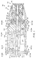
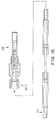
- a rotary powder dispenser 38 includes a manifold 40.
- Manifold 40 illustratively is constructed from, for example, Acetron® GP general purpose acetal available from DSM Engineering Plastic Products, Incorporated, Reading, Pennsylvania 19612-4235.
- An air turbine motor assembly 42 is mounted from a front side 44 of manifold 40 and extends forward therefrom.
- Motor assembly 42 includes a turbine motor housing 46 constructed from, for example 150SA or 550SA Delrin® material, a high voltage contact plate 48 constructed from, for example, aluminum, a turbine air nozzle plate 50 constructed from, for example, aluminum, an air turbine shaft 52 having a central axial passageway 54 therethrough, a thrust bearing spacer 56 and a turbine rotor 58.
- the turbine motor assembly 42 can be, for example a part D1245-07 available from Westwind Air Bearings, Inc., 745 Phoenix Drive, Ann Arbor, Michigan 48108.
- A, for example, glass reinforced Delrin® feed tube 59 extends down the center of passageway 54.
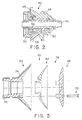
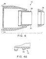
- a powder bell cup assembly 60 is threaded onto front end 62 of shaft 52.
- Powder bell cup assembly 60 includes a bell cup 64 constructed from, for example, filled or unfilled polyetheretherketone (PEEK), a bell cup insert or liner 66 constructed from, for example, Teflon® or Delrin® material, and a diffuser 68 also constructed from, for example, Teflon® or Delrin® material, all held together by three equally circumferentially spaced slotted flat head screws 70.
- Diffuser 68 illustratively is configured as illustrated and described in U.S.S.N. 08/377,816 filed January 25, 1995.
- the outer surfaces 74 of bell cup 64 are treated as described in U.S.S.N.
- a somewhat projectile-shaped front shroud 74 having a shaping air ring cap 76 houses the forward part of manifold 40, turbine motor assembly 42, and most of powder bell cup assembly 60 except the forwardmost portions thereof, including the powder discharge slot 78 defined between liner 66 and diffuser 68.
- Radially outwardly and axially extending ribs 80 provided on shroud 74 help define between shroud 74 and shaping air-ring cap 76 an annular shaping air slot which is provided with shaping air through passageways 81, 82, 84 provided in manifold 40, turbine housing 46, and front shroud 74, respectively.
- the complementary, mating surfaces 86, 88 of shroud 74 and manifold 40 are labyrinthine in configuration to provide longer pathways across the surfaces of these two components. This reduces the likelihood of tracking of the high magnitude electrical potential which is impressed upon, for example, high voltage contact plate 48 during operation of dispenser 38 back to, for example, grounded dispenser 38 support.
- a rear manifold plate assembly 90 includes a rear manifold mounting flange 92 attached by three equally circumferentially spaced screws 94 to a rear manifold mounting plate 96.
- the rearward surface 98 of plate 96 is finished flat and smooth.
- a generally right circular cylindrical rear shroud 100 is captured at its rearward extent in an annular groove 102 provided by adjacent surfaces of plate 96 and flange 92 and at its forward extent in an annular groove 104 provided on the rearwardly facing side of manifold 40.
- Appropriate fittings and lines connect the respective fluidized PowDeR (fittings 96-1 and 40-1 and line 91), powder cloud SHaPing air (fittings 96-3 and 40-3 and line 95), turbine DRiVing air (fittings 96-2 and 40-2 and line 93), turbine BeaRinG air 1 and 2 (fittings 96-4-1, 96-4-2, 40-4-1 and 40-4-2 and lines 97 and 103) and turbine BRaKing air ports (fittings 96-5 and 40-5 and line 101) on plate 96 and manifold 40.
- Turbine air EXHaust ports 1 and 2 (ports 96-6) in plate 96 vent turbine exhaust air from within rear shroud 100. This air is exhausted from turbine 42 through mufflers 106 fitted to the two EXHaust ports (40-6) on manifold 40.
- FiberOptic speed control fittings (40-7 and 96-7) are provided on both manifold 40 and plate 96.
- the FiberOptic speed control fitting 96-7 on plate 96 is intersected by a threaded bore 108 which extends into plate 96 from its edge 110.
- a cap screw is threaded into bore 108 to provide for the precise location of an optical fiber terminal 114 at the flat surface 98 of plate 96. This facilitates matching of the optical fiber terminal 114 to a lens mounted in a flat plate onto which plate 96 is mounted by bolts 116 for quick and easy replacement. This mechanism avoids the time consuming necessity of aligning terminal 114 with the lens if dispenser 38 should have to be removed for any reason including replacement by a similarly designed dispenser.
- the fluidised PowDeR (96-1), powder cloud SHaPing air (96-3), turbine DRiVing (air 96-2), turbine BeaRinG air (96-4-1 and 96-4-2) and turbine BRaKing air (96-5) ports on surface 98 are provided with surrounding O-ring seals 99.
- a generally right rectangular cylindrical boss 120 is provided on the forward or inside surface 122 of plate 96.
- a generally right circular cylindrical relief 124 is provided on the rearward surface of manifold 40 directly opposite boss 120.
- An ITW Ransburg MICRO-PAKTM high voltage transformer and cascade-type voltage multiplier 126 is captured between boss 120 and relief 124.
- the floor 128 of relief 124 is labyrinthine to complement the configuration of high magnitude potential output end 130 of high voltage multiplier 126. Again, this configuration provides longer pathways across the surfaces of multiplier 126 and manifold 40 from the high magnitude potential terminal 131 of multiplier 126 to ground.
- Manifold 40, turbine motor assembly 42 and front shroud 74 are supported from rear manifold plate 96 by four equally circumferentially spaced support rods 132 which have threaded ends for threading into complementarily threaded holes 133 provides therefor in manifold 40.
- Support rods 132 are attached to plate 96 by cap screws 135.
- the 2 BRG port couples the air bearing to a pressure sensing switch, not shown. If the switch senses the loss of pressure in the air bearing, the flows of fluidized powder coating material and driving air are halted and the turbine 42 is permitted to coast to a stop in an effort to save the turbine 42.
- Low alternating current voltage for example 12VAC-30VAC
- LowVoltage connector 96-8 is supplied through the LowVoltage connector 96-8 on plate 96 to the low voltage terminals of multiplier 126.
- LowVoltage connector 96-8 is also held in place by a cap screw (not shown) threaded into a bore 137 in the edge 110 of plate 96. Bore 137 intersects the bore into which connector 96-8 is fitted.
- A, for example, phosphor bronze, wire 136 has several coils of compression spring 138 formed at one end thereof. The end 140 of wire 136 opposite spring 138 fits into the cavity in multiplier 126 in which terminal 131 is provided. The spring 138 is compressed in contact with high voltage contact plate 48 during assembly of turbine 42 to manifold 40.
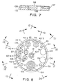
- BeaRinG air for turbine 42 is supplied from fitting 40-4-1 through passageways 144 to the air bearing 145 of turbine 42. This bearing air is sensed through passageways 146 by the above mentioned air BeaRinG pressure sensing switch connected to fitting 40-4-2. If BeaRinG air pressure is present at fitting 40-4-2, DRiVing air for turbine 42 flows forward through fitting 40-2 and passageways 150 from which it flows through the turbine 42 nozzles 152 and against the blades of the turbine rotor 58 to rotate rotor 58 and the powder bell cup assembly 60 mounted on the end 62 of shaft 52.
- Turbine 42 rotation rate signals are coupled back through, for example, a DeVilbiss Ransburg model LSMC 5003 inductive-to-fiber optic signal transmitter 156 which generates a pulse of light each time it senses the passage of a small magnetic disk (not shown) mounted in the rearwardly facing surface of rotor 58 facing transmitter 156.
- This signal is transmitted through fiber optic coupler 114 to surface 98 of plate 96 for further transmission through, for example, another similar fiber optic coupler (not shown) to turbine 42 speed control equipment (not shown) which controls the supply of DRiVing air to fitting 96-2, thereby controlling the turbine 42 rotation rate.
- BRaKing air to slow the turbine 42 rotation rate is supplied from fitting 40-5 through passageways 160 to a braking air nozzle 162 which directs braking air, when it is supplied to fitting 40-5 at braking air buckets formed in the rearwardly facing surface of rotor 58.
- Exhaust air from the low pressure side 164 of turbine 42 is exhausted through passageways 40-6 and mufflers 106 into rear shroud 100. From shroud 100, the exhaust air is vented through the 1 EXHaust and 2 EXHaust ports in plate 96. In this way, the turbine 42 exhaust is conducted in a direction away from the area radially directly outwardly from slot 78 where the dispensed powder cloud is formed and sustained, rather than being exhausted in a direction generally toward the powder cloud.
- the powder cloud is shaped by SHaPing air supplied through fitting 96-3, line 95, fitting 40-3 and passageways 81, 82 and 84.
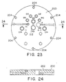
- a mating plate 200 has a flat forward surface 202 facing the rearward surface 98 of plate 96. Threaded openings 204 are circumferentially equally spaced around surface 202 for receiving cap screws 206 in flange 92. Tightening of cap screws 206 in openings 204 compresses the O-rings 99 between surfaces 98 and 202 around mating fluidized PowDeR, DRiVing air, SHaPing air, BeaRinG air 1 and 2, BRaKing air, FiberOptic and EXHaust air 1 and 2 openings in both of plates 96 and 200.
- This constructions effectively seals each of these passageways anytime the two plate 96, 200 are so secured to each other, and permits the quick and easy disconnection, reconnection and, if necessary or desirable, replacement of dispenser 38 with another dispenser of like or similar configuration.
- fitting 96-1 includes a nipple 210 provided with an additional O-ring seal 99.
- the nipple 210 of fitting 96-1 slides into, and is sealed by this additional O-ring 99 within, a relief 212 provided for the nipple 210 in surface 202 of plate 200.
- Plate 200 is mounted on any desired type of mounting, such as a stand, reciprocator, booth wall or the like, which presents powder bell cup assembly 60 at a suitable position adjacent articles to be coated by powder coating material to be dispensed therefrom.
Landscapes
- Electrostatic Spraying Apparatus (AREA)
- Coating Apparatus (AREA)
- Nozzles (AREA)
Applications Claiming Priority (2)
| Application Number | Priority Date | Filing Date | Title |
|---|---|---|---|
| US794869 | 1997-02-05 | ||
| US08/794,869 US6328224B1 (en) | 1997-02-05 | 1997-02-05 | Replaceable liner for powder coating apparatus |
Publications (2)
| Publication Number | Publication Date |
|---|---|
| EP0861691A1 true EP0861691A1 (de) | 1998-09-02 |
| EP0861691B1 EP0861691B1 (de) | 2004-03-10 |
Family
ID=25163931
Family Applications (1)
| Application Number | Title | Priority Date | Filing Date |
|---|---|---|---|
| EP97122069A Expired - Lifetime EP0861691B1 (de) | 1997-02-05 | 1997-12-15 | Auswechselbare Auskleidung für den Glockenkörper eines Rotationszerstäubers |
Country Status (5)
| Country | Link |
|---|---|
| US (1) | US6328224B1 (de) |
| EP (1) | EP0861691B1 (de) |
| JP (1) | JPH10216568A (de) |
| CA (1) | CA2226201C (de) |
| DE (1) | DE69728030T2 (de) |
Cited By (2)
| Publication number | Priority date | Publication date | Assignee | Title |
|---|---|---|---|---|
| DE10053294C1 (de) * | 2000-10-27 | 2002-07-04 | Eisenmann Lacktechnik Kg | Hochrotationszerstäuber zur Aufbringung von Pulverlack |
| WO2005110005A1 (en) * | 2004-05-18 | 2005-11-24 | Lind Finance & Development Ab | Painting bell |
Families Citing this family (19)
| Publication number | Priority date | Publication date | Assignee | Title |
|---|---|---|---|---|
| US6793150B2 (en) | 2002-06-03 | 2004-09-21 | Illinois Tool Works, Inc. | Bell cup post |
| US6889921B2 (en) * | 2002-09-30 | 2005-05-10 | Illinois Tool Works Inc. | Bell cup skirt |
| US7128277B2 (en) | 2003-07-29 | 2006-10-31 | Illinois Tool Works Inc. | Powder bell with secondary charging electrode |
| US20050023385A1 (en) * | 2003-07-29 | 2005-02-03 | Kui-Chiu Kwok | Powder robot gun |
| US20050056212A1 (en) * | 2003-09-15 | 2005-03-17 | Schaupp John F. | Split shroud for coating dispensing equipment |
| FR2860996B1 (fr) * | 2003-10-20 | 2005-12-16 | Sames Technologies | Projecteur rotatif de produit de revetement et installation de projection de produit de revetement comprenant un tel projecteur |
| US20050173556A1 (en) * | 2004-02-09 | 2005-08-11 | Kui-Chiu Kwok | Coating dispensing nozzle |
| CN100512975C (zh) * | 2005-06-02 | 2009-07-15 | Abb株式会社 | 旋转喷雾头式涂装机 |
| GB0625583D0 (en) * | 2006-12-21 | 2007-01-31 | Itw Ltd | Paint spray apparatus |
| FR2915115B1 (fr) * | 2007-04-23 | 2010-09-10 | Sames Technologies | Organe de pulverisation,dispositif de projection comportant un tel organe,installation de projection et methode de nettoyage d'un tel organe |
| US8371517B2 (en) * | 2007-06-29 | 2013-02-12 | Illinois Tool Works Inc. | Powder gun deflector |
| US8602326B2 (en) * | 2007-07-03 | 2013-12-10 | David M. Seitz | Spray device having a parabolic flow surface |
| US8096264B2 (en) | 2007-11-30 | 2012-01-17 | Illinois Tool Works Inc. | Repulsion ring |
| US10155233B2 (en) * | 2008-04-09 | 2018-12-18 | Carlisle Fluid Technologies, Inc. | Splash plate retention method and apparatus |
| US10150123B2 (en) | 2012-04-12 | 2018-12-11 | Nordson Corporation | Powder spray gun comprising a wear resistant electrode support |
| US10857560B2 (en) | 2015-09-17 | 2020-12-08 | Honda Motor Co., Ltd. | Rotary atomization type painting device and atomization head |
| CN112059198A (zh) * | 2020-09-24 | 2020-12-11 | 江苏威拉里新材料科技有限公司 | 一种金属真空气雾化设备用下锥筒 |
| US12458994B2 (en) * | 2021-01-14 | 2025-11-04 | Fanuc America Corporation | Wear resistant distributor post |
| CN114392854A (zh) * | 2022-01-21 | 2022-04-26 | 艾卡(南通)智能科技有限公司 | 一种成型空气环 |
Citations (7)
| Publication number | Priority date | Publication date | Assignee | Title |
|---|---|---|---|---|
| GB726559A (en) * | 1953-02-13 | 1955-03-23 | Kestner Evaporator And Enginee | Improvements in or relating to rotary spraying devices |
| GB1107060A (en) * | 1965-06-24 | 1968-03-20 | Inducal Berlin Veb | Spray gun |
| EP0104394A2 (de) * | 1982-08-28 | 1984-04-04 | Hermann Behr & Sohn GmbH & Co. | Einrichtung zum Vernebeln flüssiger Farbe |
| US4785995A (en) * | 1986-03-18 | 1988-11-22 | Mazda Motor Corporation | Methods and apparatus for conducting electrostatic spray coating |
| EP0450877A2 (de) * | 1990-03-30 | 1991-10-09 | Nordson Corporation | Rotationszerstäuber mit integrierter Farbwechselvorrichtung und Fluiddruckregler |
| DE4335507A1 (de) * | 1993-10-19 | 1995-04-27 | Hestermann Gerhard | Pulversprühorgan |
| JPH08155348A (ja) * | 1994-11-30 | 1996-06-18 | Trinity Ind Corp | 静電塗装機 |
Family Cites Families (27)
| Publication number | Priority date | Publication date | Assignee | Title |
|---|---|---|---|---|
| US2690901A (en) * | 1951-01-22 | 1954-10-05 | Gunite Concrete And Constructi | Undulated nozzle tip |
| US2989241A (en) * | 1956-07-16 | 1961-06-20 | Ransburg Electro Coating Corp | Apparatus for electrostatic spray coating |
| US3111179A (en) * | 1960-07-26 | 1963-11-19 | A And B Metal Mfg Company Inc | Jet nozzle |
| NL277060A (de) | 1961-04-14 | |||
| US4114564A (en) | 1963-06-13 | 1978-09-19 | Ransburg Corporation | Electrostatic coating apparatus |
| US3870232A (en) | 1972-05-26 | 1975-03-11 | Air Ind | Nozzle for projecting powdered solid products |
| DE2446022C3 (de) | 1974-09-26 | 1985-10-24 | ESB Elektrostatische Spritz- und Beflockungsgesellschaft G.F. Vöhringer GmbH, 7758 Meersburg | Vorrichtung zum elektrostatischen Beschichten von Gegenständen mit flüssigem oder pulverförmigem Beschichtungsmaterial |
| US4110486A (en) | 1975-01-16 | 1978-08-29 | Adrien Lacchia | Electrostatic powder coating method |
| DE2519831A1 (de) | 1975-05-03 | 1976-11-11 | Platsch Zerstaeubung Albin | Vorrichtung zur puderbestaeubung |
| CH622972A5 (en) | 1977-09-09 | 1981-05-15 | Gema Ag | Device for electrostatic powder coating of objects |
| CH623751A5 (de) | 1977-12-23 | 1981-06-30 | Gema Ag | |
| ES468633A1 (es) | 1978-04-07 | 1978-12-01 | Rosal Vila Juan | Mejoras introducidas en los aparatos para el recubrimiento con polvo electrostatico de objetos. |
| US4381079A (en) | 1980-11-03 | 1983-04-26 | Ransburg Corporation | Atomizing device motor |
| US4447008A (en) | 1980-11-03 | 1984-05-08 | Ransburg Corporation | Atomizing device motor |
| CH670138A5 (en) * | 1985-08-07 | 1989-05-12 | Stoody Deloro Stellite Inc | Closure for cone valves acting as fluid regulator - has replaceable hard metal wear parts to prolong life of fitting |
| EP0236794B1 (de) | 1986-03-13 | 1991-01-02 | ITW Gema AG | Elektrostatische Sprüheinrichtung für Beschichtungspulver |
| FR2605533A1 (fr) | 1986-10-28 | 1988-04-29 | Sames Sa | Projecteur de produit pulverulent en suspension dans l'air |
| US4815241A (en) * | 1986-11-24 | 1989-03-28 | Whitemetal Inc. | Wet jet blast nozzle |
| DE3904437A1 (de) | 1989-02-14 | 1990-08-16 | Gema Ransburg Ag | Spruehpistole zum elektrostatischen spruehbeschichten |
| DE3904438A1 (de) | 1989-02-14 | 1990-08-16 | Gema Ransburg Ag | Spruehbeschichtungsgeraet zum elektrostatischen spruehbeschichten |
| FR2648937B1 (fr) | 1989-06-26 | 1991-09-27 | Avenay Partners | Outil d'organisation et/ou de planification |
| GB9015609D0 (en) * | 1990-07-16 | 1990-09-05 | De Beers Ind Diamond | Tool insert |
| DE69132062T2 (de) | 1990-12-27 | 2000-09-07 | Matsuo Sangyo Co. Ltd., Osaka | Vorrichtung zur Zuführung von Pulverfarben |
| FR2692173B1 (fr) | 1992-06-10 | 1994-09-02 | Sames Sa | Dispositif de projection électrostatique d'un produit de revêtement en poudre à tête d'ionisation tournante. |
| US5633306A (en) * | 1992-12-03 | 1997-05-27 | Ransburg Corporation | Nonincendive rotary atomizer |
| US5634598A (en) * | 1994-09-20 | 1997-06-03 | Minerals Technologies, Inc. | Abrasion resistant lined sweep nozzle |
| US5632448A (en) | 1995-01-25 | 1997-05-27 | Ransburg Corporation | Rotary powder applicator |
-
1997
- 1997-02-05 US US08/794,869 patent/US6328224B1/en not_active Expired - Fee Related
- 1997-12-15 EP EP97122069A patent/EP0861691B1/de not_active Expired - Lifetime
- 1997-12-15 DE DE69728030T patent/DE69728030T2/de not_active Expired - Fee Related
-
1998
- 1998-01-05 CA CA002226201A patent/CA2226201C/en not_active Expired - Fee Related
- 1998-02-05 JP JP10024409A patent/JPH10216568A/ja active Pending
Patent Citations (7)
| Publication number | Priority date | Publication date | Assignee | Title |
|---|---|---|---|---|
| GB726559A (en) * | 1953-02-13 | 1955-03-23 | Kestner Evaporator And Enginee | Improvements in or relating to rotary spraying devices |
| GB1107060A (en) * | 1965-06-24 | 1968-03-20 | Inducal Berlin Veb | Spray gun |
| EP0104394A2 (de) * | 1982-08-28 | 1984-04-04 | Hermann Behr & Sohn GmbH & Co. | Einrichtung zum Vernebeln flüssiger Farbe |
| US4785995A (en) * | 1986-03-18 | 1988-11-22 | Mazda Motor Corporation | Methods and apparatus for conducting electrostatic spray coating |
| EP0450877A2 (de) * | 1990-03-30 | 1991-10-09 | Nordson Corporation | Rotationszerstäuber mit integrierter Farbwechselvorrichtung und Fluiddruckregler |
| DE4335507A1 (de) * | 1993-10-19 | 1995-04-27 | Hestermann Gerhard | Pulversprühorgan |
| JPH08155348A (ja) * | 1994-11-30 | 1996-06-18 | Trinity Ind Corp | 静電塗装機 |
Non-Patent Citations (1)
| Title |
|---|
| PATENT ABSTRACTS OF JAPAN vol. 096, no. 010 31 October 1996 (1996-10-31) * |
Cited By (2)
| Publication number | Priority date | Publication date | Assignee | Title |
|---|---|---|---|---|
| DE10053294C1 (de) * | 2000-10-27 | 2002-07-04 | Eisenmann Lacktechnik Kg | Hochrotationszerstäuber zur Aufbringung von Pulverlack |
| WO2005110005A1 (en) * | 2004-05-18 | 2005-11-24 | Lind Finance & Development Ab | Painting bell |
Also Published As
| Publication number | Publication date |
|---|---|
| DE69728030D1 (de) | 2004-04-15 |
| JPH10216568A (ja) | 1998-08-18 |
| DE69728030T2 (de) | 2004-07-22 |
| EP0861691B1 (de) | 2004-03-10 |
| CA2226201A1 (en) | 1998-08-05 |
| MX9800495A (es) | 1998-08-30 |
| CA2226201C (en) | 2003-03-18 |
| US6328224B1 (en) | 2001-12-11 |
Similar Documents
| Publication | Publication Date | Title |
|---|---|---|
| EP0861691B1 (de) | Auswechselbare Auskleidung für den Glockenkörper eines Rotationszerstäubers | |
| CA2225088C (en) | Quick disconnect for powder coating apparatus | |
| US5632448A (en) | Rotary powder applicator | |
| US4776520A (en) | Rotary atomizer | |
| US4936510A (en) | Rotary automizer with air cap and retainer | |
| US4997130A (en) | Air bearing rotary atomizer | |
| EP0379373B1 (de) | Elektrostatisches Sprühbeschichtungsgerät mit Rotationszerstäuber | |
| CA1223119A (en) | Rotary atomizer coater | |
| US7128277B2 (en) | Powder bell with secondary charging electrode | |
| EP0828565B1 (de) | Pulverzerstäuber mit rotierendem sprühkopf | |
| EP0250942A2 (de) | Rotierender Zerstäuber mit Luftlager | |
| US7721976B2 (en) | High speed rotating atomizer assembly | |
| EP0509101A1 (de) | Elektrostatische beschichtungsvorrichtung | |
| US4936507A (en) | Rotary atomizer with high voltage isolating speed measurement | |
| US4936509A (en) | Air turbine driven rotary atomizer | |
| EP0803293A1 (de) | Rotierender sprühkopf | |
| US4899936A (en) | Rotary atomizer with protective shroud | |
| EP0857515A2 (de) | Abluftstrom einer Turbine einer Pulverbeschichtungsvorrichtung | |
| US6889921B2 (en) | Bell cup skirt | |
| US6722591B2 (en) | High-speed rotary atomizer for applying powder coating | |
| EP0422813B1 (de) | Elektrostatische Sprühvorrichtung für die Beschichtung | |
| MXPA98000495A (en) | Replaceable lining for a covered powder supply apparatus | |
| EP4049760B1 (de) | Elektrostatische beschichtungshandpistole und elektrostatisches beschichtungsverfahren | |
| CA2563231C (en) | A high speed rotating atomizer assembly |
Legal Events
| Date | Code | Title | Description |
|---|---|---|---|
| PUAI | Public reference made under article 153(3) epc to a published international application that has entered the european phase |
Free format text: ORIGINAL CODE: 0009012 |
|
| 17P | Request for examination filed |
Effective date: 19971215 |
|
| AK | Designated contracting states |
Kind code of ref document: A1 Designated state(s): DE FR GB |
|
| AX | Request for extension of the european patent |
Free format text: AL;LT;LV;MK;RO;SI |
|
| AKX | Designation fees paid |
Free format text: DE FR GB |
|
| RBV | Designated contracting states (corrected) |
Designated state(s): DE FR GB |
|
| 17Q | First examination report despatched |
Effective date: 20021115 |
|
| REG | Reference to a national code |
Ref country code: GB Ref legal event code: FG4D |
|
| GRAH | Despatch of communication of intention to grant a patent |
Free format text: ORIGINAL CODE: EPIDOS IGRA |
|
| GRAS | Grant fee paid |
Free format text: ORIGINAL CODE: EPIDOSNIGR3 |
|
| GRAA | (expected) grant |
Free format text: ORIGINAL CODE: 0009210 |
|
| AK | Designated contracting states |
Kind code of ref document: B1 Designated state(s): DE FR GB |
|
| REF | Corresponds to: |
Ref document number: 69728030 Country of ref document: DE Date of ref document: 20040415 Kind code of ref document: P |
|
| ET | Fr: translation filed | ||
| PLBE | No opposition filed within time limit |
Free format text: ORIGINAL CODE: 0009261 |
|
| STAA | Information on the status of an ep patent application or granted ep patent |
Free format text: STATUS: NO OPPOSITION FILED WITHIN TIME LIMIT |
|
| 26N | No opposition filed |
Effective date: 20041213 |
|
| PGFP | Annual fee paid to national office [announced via postgrant information from national office to epo] |
Ref country code: DE Payment date: 20090202 Year of fee payment: 12 |
|
| PGFP | Annual fee paid to national office [announced via postgrant information from national office to epo] |
Ref country code: GB Payment date: 20081229 Year of fee payment: 12 |
|
| PGFP | Annual fee paid to national office [announced via postgrant information from national office to epo] |
Ref country code: FR Payment date: 20081217 Year of fee payment: 12 |
|
| GBPC | Gb: european patent ceased through non-payment of renewal fee |
Effective date: 20091215 |
|
| REG | Reference to a national code |
Ref country code: FR Ref legal event code: ST Effective date: 20100831 |
|
| PG25 | Lapsed in a contracting state [announced via postgrant information from national office to epo] |
Ref country code: FR Free format text: LAPSE BECAUSE OF NON-PAYMENT OF DUE FEES Effective date: 20091231 |
|
| PG25 | Lapsed in a contracting state [announced via postgrant information from national office to epo] |
Ref country code: DE Free format text: LAPSE BECAUSE OF NON-PAYMENT OF DUE FEES Effective date: 20100701 |
|
| PG25 | Lapsed in a contracting state [announced via postgrant information from national office to epo] |
Ref country code: GB Free format text: LAPSE BECAUSE OF NON-PAYMENT OF DUE FEES Effective date: 20091215 |