EP0861786B1 - Vorrichtung zum Handhaben oder Herstellen von Packungen - Google Patents
Vorrichtung zum Handhaben oder Herstellen von Packungen Download PDFInfo
- Publication number
- EP0861786B1 EP0861786B1 EP98100439A EP98100439A EP0861786B1 EP 0861786 B1 EP0861786 B1 EP 0861786B1 EP 98100439 A EP98100439 A EP 98100439A EP 98100439 A EP98100439 A EP 98100439A EP 0861786 B1 EP0861786 B1 EP 0861786B1
- Authority
- EP
- European Patent Office
- Prior art keywords
- push rod
- contact
- elements
- switching
- folding
- Prior art date
- Legal status (The legal status is an assumption and is not a legal conclusion. Google has not performed a legal analysis and makes no representation as to the accuracy of the status listed.)
- Expired - Lifetime
Links
- 230000033001 locomotion Effects 0.000 claims description 30
- 239000003999 initiator Substances 0.000 claims description 12
- 238000012544 monitoring process Methods 0.000 claims description 10
- 230000008878 coupling Effects 0.000 claims description 3
- 238000010168 coupling process Methods 0.000 claims description 3
- 238000005859 coupling reaction Methods 0.000 claims description 3
- 239000005022 packaging material Substances 0.000 claims description 3
- 210000000056 organ Anatomy 0.000 description 19
- 238000004806 packaging method and process Methods 0.000 description 13
- 235000019504 cigarettes Nutrition 0.000 description 9
- 239000000463 material Substances 0.000 description 4
- 230000005540 biological transmission Effects 0.000 description 3
- 230000007257 malfunction Effects 0.000 description 3
- 238000004519 manufacturing process Methods 0.000 description 3
- 230000006378 damage Effects 0.000 description 2
- 238000012806 monitoring device Methods 0.000 description 2
- 239000000523 sample Substances 0.000 description 2
- ATJFFYVFTNAWJD-UHFFFAOYSA-N Tin Chemical compound [Sn] ATJFFYVFTNAWJD-UHFFFAOYSA-N 0.000 description 1
- 230000004888 barrier function Effects 0.000 description 1
- 230000001066 destructive effect Effects 0.000 description 1
- 238000011156 evaluation Methods 0.000 description 1
- 239000011888 foil Substances 0.000 description 1
- 230000005693 optoelectronics Effects 0.000 description 1
- 239000000700 radioactive tracer Substances 0.000 description 1
- 230000001960 triggered effect Effects 0.000 description 1
Images




Classifications
-
- B—PERFORMING OPERATIONS; TRANSPORTING
- B65—CONVEYING; PACKING; STORING; HANDLING THIN OR FILAMENTARY MATERIAL
- B65B—MACHINES, APPARATUS OR DEVICES FOR, OR METHODS OF, PACKAGING ARTICLES OR MATERIALS; UNPACKING
- B65B57/00—Automatic control, checking, warning, or safety devices
-
- B—PERFORMING OPERATIONS; TRANSPORTING
- B65—CONVEYING; PACKING; STORING; HANDLING THIN OR FILAMENTARY MATERIAL
- B65B—MACHINES, APPARATUS OR DEVICES FOR, OR METHODS OF, PACKAGING ARTICLES OR MATERIALS; UNPACKING
- B65B19/00—Packaging rod-shaped or tubular articles susceptible to damage by abrasion or pressure, e.g. cigarettes, cigars, macaroni, spaghetti, drinking straws or welding electrodes
- B65B19/28—Control devices for cigarette or cigar packaging machines
Definitions
- the invention relates to a device for handling or manufacturing of packaging made of packaging material, such as paper, cardboard, Foil etc., with a movable handling unit, in particular with a rotating (folding) turret and with movable organs on the handling device, such as folding organs, Pressure elements, plungers, slides etc.
- a device for handling or manufacturing of packaging made of packaging material such as paper, cardboard, Foil etc.
- a movable handling unit in particular with a rotating (folding) turret and with movable organs on the handling device, such as folding organs, Pressure elements, plungers, slides etc.
- movable organs on the handling device such as folding organs, Pressure elements, plungers, slides etc.
- Such a device is a packaging machine or a part of it, but can also be part of a packaging machine subordinate device, like a dry turret, harden finished packs in its area.
- movable organs one Folding turret or other unit, in particular folding lever, reciprocating plungers etc. with regard to possible misalignments to monitor, ie with regard to deviations from the correct position within a movement cycle.
- Approximately Detected incorrect positions generate an error signal, which Depending on the circumstances, the packaging machine may be switched off causes.
- the object underlying the invention is a reliable, permanently effective even in an unfavorable environment Monitoring the moving parts of a packaging machine to propose the malposition of the monitored organs triggers an error signal.
- the device according to the invention is used to achieve this object characterized by mechanical probes that malfunction or malposition of the movable organ through the continued movement of the handling unit can be acted upon are an error signal due to relative movement can generate.
- the monitoring device for movable organs works mechanically. Otherwise they are generally used for monitoring optoelectronic organs, especially light barriers, because of the errors emanating from these avoided.
- the invention (Mechanical) monitoring device is particularly suitable in packaging machines where the monitored organs entirely or partially housed in enclosed areas and are constantly supplied with oil or in an oil bath to run.
- a mechanical Actuator or actuating gear to detect malpositions be located inside the enclosed space, while organs that trigger errors, for example non-contact electrical switching devices (initiators) outside of this Area.
- Another subject of the invention is the design of Tappet of a folding turret, such that when overloaded of such a tappet due to a failure of the tappet of a drive can be uncoupled. This decoupling leads to avoidance of destructive movements of the ram, but also too a malposition thereof which is recognized according to the invention.
- the invention is particularly advantageously applicable to a Folding turret for the manufacture of cigarette packs of the type Soft-cup.
- a folding turret is in with several tappets equipped to move axially parallel to push a cigarette group out of a folding mandrel under Taking along the folded ones arranged on the outside of the folding mandrel Packaging blanks.
- the invention works to monitor the correct reciprocating motion this pestle.
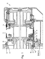
- a preferred application example is shown in the drawings, namely a folding turret 10 as part of a packaging machine for the production of cigarette packs of the Type soft cup. More details about the structure and the Operation of such a folding turret 10 result from DE 196 54 394.0.
- the folding turret 10 is provided with folding mandrels 11 along the circumference Mistake. It is elongated, thin-walled Hollow body for holding a group of cigarettes. On the outside of the folding mandrel 11 are during the rotational movement of the Folding turret 10 cuts from packaging material in succession folded, namely in particular an inner wrapping Tinfoil or paper and a cup-shaped outer wrapping Paper.
- Elongated plungers 12 serve this purpose, the along the circumference of the folding turret 10 in parallel to the axis Direction stored and each folding mandrel 11 are assigned.
- the ram 12 joins a plunger head 13 via an open side into the folding mandrel 11 and pushes the cigarette group in, taking the outside blanks lying against the folding mandrel 11.
- the unit from the cigarette group and cut to an adjacent position Pass folding pocket 14 of the folding turret 10 and in their Area folded.
- the plunger 12 then returns from the Extending position (Fig. 1 below) into the starting position (Fig. 1 above) back.
- the back and forth movements of the plunger 12 are positively controlled in accordance with the rotational movement of the folding turret 10.
- An end region of the plunger 12 that is remote from the plunger head 13 is provided with a transverse roller 15. This is running upon rotation of the folding turret 10 in a control groove 16, the in turn in a fixed part of the folding turret 10 in The circumferential direction of the same runs, namely in a coaxial mounted control body 17.
- the control groove 16 is designed so that by the running in this tracer roller 15 back and forth Motion is transmitted to the plunger 12.
- the feeler roller is 15 laterally attached to a carriage 18, which in turn with the plunger 12 is connected.
- the carriage 18 is accordingly with the plunger 12 reciprocated.
- the Carriage 18 out, on two at a distance from each other arranged, parallel guide rods 19, 20.
- the plunger 12 runs in the middle between the two guide rods 19, 20.
- the carriage 18 serves as a releasable coupling in the present case between feeler roller 15 and plunger 12.
- the slide 18 itself is slidable for this purpose on the trained as a rod Ram 12 stored.
- To connect the slide 18 with the plunger 12 serves a crosspiece 21, which with the Ram 12 is connected, at the end of the same via a Connection screw 22.
- the plate-shaped cross piece 21 is held in detachable connection with the carriage 18, namely in the present embodiment via (Two) permanent magnets 23, 24.
- the permanent magnets 23 are in recesses 25 of the carriage 18 positioned such that the Permanent magnets 23, 24 on the (metallic) cross piece 21 facing The page lies approximately flush with the back of the Carriage 18. By the magnetic force of the permanent magnets 23, 24 becomes the connection between the carriage 18 and the crosspiece 21 consequently produced with the plunger 12.
- the carriage 18 is for receiving the permanent magnets 23, 24 or to form the recesses 25 on the underside or inside with an approximately rectangular, centrally arranged approach 26 provided. This also serves to ensure an exact Relative position of the plunger 12 to the (guided) slide 18.
- the crosspiece 21 is namely on both sides with angular Fitting pieces 27, 28 provided. These come in a form-fitting manner formed by the contour of the carriage 18 and the neck 26 angular recesses and thus ensure a rotation of the plunger 12.
- the releasable connection of the plunger 12 with its drive, that is the feeler roller 15, should avoid consequences of a malfunction, in particular Breakage caused by overloading the ram 12. If, for example A material jam occurs in the area of the folding mandrel 11, should be prevented that the plunger 12 or Ram head 13 by the positive drive of the feeler roller 15 under Destruction of sensitive organs continues in the axial direction becomes. If a certain thrust of the feeler roller 15 is exceeded, the connecting force of the permanent magnets 23, 24 overcome. The carriage 18 detaches from the plunger 12 or from the cross piece 21 and is without transmission of a feed force slidably moved on the plunger 12, according to the Movement of the feeler roller 15.
- feelers are acted upon in the path of motion of the plunger 12 are positioned. These are around thin-walled sensing tabs 29 made of flat material, 30, 31. These are fixed along the circumference of the folding turret 10 positioned.
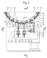
- Fig. 4 is a monitoring unit 32 of three in the direction of movement successive tactile flags 29, 30, 31 on the outer circumference of the folding turret 10 positioned.
- An application these sensing elements or sensing lugs 29, 30, 31 cause an error signal due to a movement, namely swiveling movement of the Touch flags 29, 30, 31.
- the tactile flags 29, 30, 31 are positioned so that each conceivable misalignment of the plunger 12 one of the sensing lugs 29, 30, 31 is applied. This is monitored by the plunger head 13 distal end of the plunger 12, namely the cross piece 21. This is with a projection or a radially outward Provide nose 33, one of the tactile flags 29, 30, 31 acted upon in the event of a malposition.
- the nose 33 as part of the Ram 12 moves when the movement cycle is correct Ram 12 outside the position of the feelers 29, 30, 31.
- Fig. 6 is the path of movement 34 of the nose 33 as a dash-dotted line Line shown.
- the tactile flags 29, 30, 31 are for this Purpose with different widths to fit all in Consider relative positions of the nose 33.
- the first probe flag in the direction of rotation of the folding turret 10 29 is designed as a relatively narrow strip of material, around the possible position of the nose 33 in the area of the starting position to cover the plunger 12.
- the tactile flag 30 In the direction of rotation follows the tactile flag 30, which in the folding turret 10 or the movement path the area facing the nose 33 with a strip-shaped Widening 35 is provided.
- the third tactile flag 31 extends over the full amplitude of movement of the nose 33 in Axial direction seen.
- the tactile flag 31 also consists of a narrow strip of material with a transverse widening 36th
- sensing elements or sensing lugs 29, 30, 31 are in the lower area of the folding turret 10 positioned.
- the tactile flag 29 is because of a laterally offset arrangement with a bend 37 provided, at the end of an angled leg 38 for loading is arranged through the nose 33.
- each flag 29, 30, 31 with a rotatable switching shaft 39, 40, 41 connected. These are pivoted with the ends Switching shafts 39, 40, 41 are mounted in a housing 42, which open to the turret 10 or the housing thereof is.
- the switching shafts 39, 40, 41 occur with an actuation end 43 from a wall of the housing 42 from this. The are actuated by the switching shafts 39, 40, 41 switching elements outside the housing 42.
- non-contact Switches namely so-called initiators 44, 45, 46 as switching elements intended.
- These initiators 44, 45, 46 are through Switch lever 47 is actuated or acted upon, the contactless be moved past one end of the initiator 44, 45, 46.
- the shift lever 47 are in one Position immediately adjacent to the assigned initiator 44, 45, 46 (position with solid lines in Fig. 5).
- the shift lever 47 at Actuation of an initiator 44, 45, 46 based on a detected Error, the shift lever 47 in one way or another Position outside the immediate vicinity of the initiator 44, 45, 46 moves (dash-dotted in Fig. 5).
- a signal is triggered in the initiator 44, 45, 46, which for example fed to a central computer for evaluation becomes.
- the shift levers are directly at one end, namely at the actuation end 43, the switching shafts 39, 40, 41 arranged as arms protruding on one side.
- the described actuating gear is with a Provide reset device in the normal or initial position.
- each transverse Swivel lever 48 arranged at the ends of the switching shafts 39, 40, 41 or at the actuating end 43 arranged.
- the ends are again biased springs, namely tension springs 49, 50, the other End is firmly anchored.
- the tension springs 49, 50 pull the Swivel lever 48 and thus the shift shaft 39, 40, 41 in the Normal position (transverse position of the pivot lever 48). Actuation of the shift lever 47 accordingly takes place against the Tension springs 49 or 50 loaded.
- the tactile flags 29, 30, 31 are in the event of an incorrect position of the Ram 12 and thus the nose 33 acted upon by this. by virtue of the relative position is the nose 33 in such a Trap against one of the feeler flags 29, 30, 31 moved (Fig. 5), so that this performs a pivoting movement. This is described in the Way on the switching element, namely one of the initiators 44, 45, 46.
- the monitoring unit 32 is predominantly encapsulated Area housed so that the monitoring of the plunger 12th or other organs, for example, even in an oil-supplied one Area can act.
- the transmission mechanics leads in Area of rotatable organs from the encapsulated area, namely out of the housing 42, so that suitable, even sensitive Switching elements are outside this encapsulated area.
- the monitoring described can also be used for other organs are used, for example, for pivotably moving folding members or other organs.
- the pressure-limited actuation the plunger 12 can also be designed in a different way, namely with mechanical locking elements instead of permanent magnets 23, 24.
Landscapes
- Engineering & Computer Science (AREA)
- Mechanical Engineering (AREA)
- Wrapping Of Specific Fragile Articles (AREA)
- Making Paper Articles (AREA)
- Packaging Of Special Articles (AREA)
Description
- Fig. 1
- ein Beispiel eines Faltrevolvers im Längsschnitt,
- Fig. 2
- einen unteren Bereich des Faltrevolvers, ebenfalls im Längsschnitt, bei vergrößertem Maßstab,
- Fig. 3
- einen nochmals vergrößerten Ausschnitt der Einzelheit gemäß Fig. 2, nämlich einen Vertikalschnitt in der Schnittebene III-III der Fig. 4,
- Fig. 4
- einen unteren Teil des Faltrevolvers in queraxialem Schnitt mit Überwachungsorganen,
- Fig. 5
- einen Ausschnitt der Darstellung gemäß Fig. 4 in vergrößertem Maßstab,
- Fig. 6
- eine Einzelheit der Darstellung gemäß Fig. 4, nämlich einen Horizontalschnitt in der Schnittebene VI-VI,
- Fig. 7
- ein stark vergrößertes Detail über einen Antrieb für einen Stößel im Querschnitt desselben,
- Fig. 8
- eine Schnittdarstellung zu Fig. 7 in der Schnittebene VIII-VIII.
Claims (12)
- Vorrichtung zum Handhaben oder Herstellen von Packungen aus Verpackungsmaterial, wie Papier, Karton, Folie etc., mit einem bewegbaren Handhabungsaggregat, insbesondere einem drehend angetriebenen Faltrevolver (10) und mit bewegbaren Organen am Handhabungsgerät, wie Faltorganen, Andrückorganen, Stößeln (12), Schiebern etc., gekennzeichnet, durch mechanische Tastorgane, insbesondere Tastfahnen (29, 30, 31), die bei einer Fehlfunktion oder Fehlstellung eines bewegbaren Organs durch die fortgesetzte Bewegung des Handhabungsaggregats beaufschlagbar sind und dadurch infolge Relativbewegung ein Fehlersignal erzeugen können.
- Vorrichtung nach Anspruch 1, dadurch gekennzeichnet, daß die Relativbewegung der Tastorgane - Tastfahnen (29, 30, 31) - über mechanische Stellmittel auf Sensoren übertragbar ist, insbesondere auf berührungslose Schaltorgane - sogenannte Initiatoren (44, 45, 46).
- Vorrichtung nach Anspruch 1 oder 2, dadurch gekennzeichnet, daß wenigstens Teile der mechanischen Fehlerüberwachung, mindestens die Tastorgane - Tastfahnen (29, 30, 31) - in einem abgekapselten Bereich angeordnet sind, insbesondere in einem mit Öl versorgten Bereich.
- Vorrichtung nach Anspruch 1 oder einem der weiteren Ansprüche, dadurch gekennzeichnet, daß die Bewegungen der Tastfahnen (29, 30, 31) über mechanische Stellmittel, insbesondere über drehbare Schaltwellen (39, 40, 41), auf Schaltorgane übertragbar sind, vorzugsweise auf berührungslose Schalter - Initiatoren (44, 45, 46).
- Vorrichtung nach Anspruch 4, dadurch gekennzeichnet, daß die Schaltwellen (39, 40, 41) überwiegend im abgekapselten Bereich angeordnet sind, insbesondere in einem Gehäuse (42), wobei Enden der Schaltwellen (39, 40, 41), nämlich Betätigungsenden (43), durch eine Wand des Gehäuses (42) hindurchtreten und mit einem Organ zur Betätigung der Schaltorgane verbunden sind, vorzugsweise mit einem Schalthebel für jeden Initiator (44, 45, 46).
- Vorrichtung nach Anspruch 1 oder einem der weiteren Ansprüche, dadurch gekennzeichnet, daß die Tastorgane bzw. Tastfahnen (29, 30, 31) in eine Ausgangs- bzw. Normalstellung elastisch belastet sind, vorzugsweise durch auf die Schaltwellen (39, 40, 41) wirkende, außerhalb des abgekapselten Bereichs angeordnete Zugfedern (49, 50).
- Vorrichtung nach Anspruch 1 oder einem der weiteren Ansprüche, dadurch gekennzeichnet, daß eine ortsfeste, dem Faltrevolver (10) zugeordnete Überwachungseinheit (32) mehrere in Umfangsrichtung aufeinanderfolgende Tastorgane bzw. Tastfahnen (29, 30, 31) aufweist, die aufgrund ihrer Relativstellung und Abmessung in achsparalleler Richtung jede mögliche Fehlstellung des Stößels (12) abdecken, wobei vorzugsweise die Tastfahnen (29, 30, 31) in Drehrichtung des Faltrevolvers eine zunehmende Breite aufweisen.
- Vorrichtung nach Anspruch 1 oder einem der weiteren Ansprüche, dadurch gekennzeichnet, daß an dem überwachten, bewegbaren Organ, insbesondere am Stößel (12), ein quer abstehendes Betätigungsorgan angebracht ist, insbesondere eine Nase (33), die bei einer Fehlstellung des Stößels (12) mindestens eine Tastfahne (29, 30, 31) infolge Drehbewegung des Faltrevolvers (10) beaufschlagt.
- Vorrichtung nach Anspruch 8 oder einem der weiteren Ansprüche, dadurch gekennzeichnet, daß der Betätigungsvorsprung, insbesondere die Nase (33), an einem am Ende des Stößels (12) angeordneten Querstück (21) angebracht ist, derart, daß bei einer Fehlstellung des Stößels (12) die Nase (33) in den Bereich mindestens einer Tastfahne (29, 30, 31) ragt.
- Vorrichtung nach Anspruch 1 oder einem der weiteren Ansprüche, dadurch gekennzeichnet, daß das bewegbare Organ, insbesondere der Stößel (12) über eine bei Überlastung lösbare Kupplung mit einem Stößelantrieb verbunden ist.
- Vorrichtung nach Anspruch 10 oder einem der weiteren Ansprüche, dadurch gekennzeichnet, daß der Stößel (12) durch eine seitwärts gerichtete Tastrolle (15) bewegbar ist, der in eine ortsfeste Steuernut (16) eintritt, derart, daß infolge Drehung des Faltrevolvers (10) axiale Hin- und Herbewegungen auf den Stößel (12) übertragbar sind, wobei die Tastrolle (15) lösbar mit dem Stößel (12) verbunden ist, vorzugsweise derart, daß die Tastrolle (15) an einem Schlitten (18) angebracht ist, der seinerseits über eine bei Überlastung lösbare Kupplung mit dem Stößel (12) verbunden ist.
- Vorrichtung nach Anspruch 10 oder 11 sowie einem der weiteren Ansprüche, dadurch gekennzeichnet, daß die Tastrolle (15) bzw. der Schlitten (18) über Dauermagnete (23, 24) mit dem Stößel (12) verbunden ist, vorzugsweise mit dem am Ende des Stößels (12) angeordneten Querstück (21), derart, daß bei Überlastung der frei auf dem Stößel (12) bewegbare Schlitten (18) vom Querstück (12) lösbar ist.
Applications Claiming Priority (2)
| Application Number | Priority Date | Filing Date | Title |
|---|---|---|---|
| DE19707685 | 1997-02-26 | ||
| DE19707685A DE19707685A1 (de) | 1997-02-26 | 1997-02-26 | Vorrichtung zum Handhaben oder Herstellen von Packungen |
Publications (2)
| Publication Number | Publication Date |
|---|---|
| EP0861786A1 EP0861786A1 (de) | 1998-09-02 |
| EP0861786B1 true EP0861786B1 (de) | 2003-11-05 |
Family
ID=7821542
Family Applications (1)
| Application Number | Title | Priority Date | Filing Date |
|---|---|---|---|
| EP98100439A Expired - Lifetime EP0861786B1 (de) | 1997-02-26 | 1998-01-13 | Vorrichtung zum Handhaben oder Herstellen von Packungen |
Country Status (7)
| Country | Link |
|---|---|
| US (1) | US6035603A (de) |
| EP (1) | EP0861786B1 (de) |
| JP (1) | JP4018224B2 (de) |
| CN (1) | CN1105063C (de) |
| BR (1) | BR9800765A (de) |
| DE (2) | DE19707685A1 (de) |
| ES (1) | ES2210599T3 (de) |
Families Citing this family (12)
| Publication number | Priority date | Publication date | Assignee | Title |
|---|---|---|---|---|
| IT1320970B1 (it) * | 2000-04-04 | 2003-12-18 | Gd Spa | Macchina per realizzare pacchetti di sigarette e metodo di controllodella macchina. |
| DE10115563A1 (de) | 2001-03-28 | 2002-10-02 | Focke & Co | Verpackungsmaschine für Zigaretten |
| CN100457439C (zh) * | 2005-07-13 | 2009-02-04 | 蔡光起 | 一种整体式烟标纸双翻转盒盖折叠成型机构及折叠工艺 |
| US8808157B2 (en) * | 2006-06-30 | 2014-08-19 | C. R. Bard, Inc. | Devices for assembling strands comprising radioactive seeds |
| DE102007004029A1 (de) * | 2007-01-22 | 2008-07-24 | Focke & Co.(Gmbh & Co. Kg) | Arbeitseinrichtung für Verpackungsmaschinen |
| USD635601S1 (en) * | 2010-04-14 | 2011-04-05 | Ima Safe Srl | Packaging machine |
| USD665435S1 (en) * | 2010-04-14 | 2012-08-14 | Ima Safe Srl | Distributing disk of packaging machine |
| USD635602S1 (en) * | 2010-04-14 | 2011-04-05 | Ima Safe Srl | Distributing disk of packing machine |
| DE202012102759U1 (de) * | 2012-07-23 | 2013-07-24 | Krones Aktiengesellschaft | Faltvorrichtung |
| CN110217429B (zh) * | 2019-06-06 | 2021-05-18 | 重庆智荟数创科技有限公司 | 一种键合金丝卷筒包装设备及其使用方法 |
| CN110294165B (zh) * | 2019-07-02 | 2021-05-18 | 重庆智荟数创科技有限公司 | 可对换位置的键合银丝卷筒包装装置及其方法 |
| CN112856967B (zh) * | 2019-12-16 | 2022-08-12 | 佛山市德启首饰包装有限公司 | 一种夹沿定型纸盒烘干机及使用方法 |
Family Cites Families (11)
| Publication number | Priority date | Publication date | Assignee | Title |
|---|---|---|---|---|
| US2640590A (en) * | 1948-12-09 | 1953-06-02 | Arthur H Mcclelland | Can label sorting device |
| CH388171A (de) * | 1960-06-18 | 1965-02-15 | Hesser Ag Maschf | Verfahren und Vorrichtung zum Prüfen von evakuierten Packungen aus flexiblen Packstoffen auf Dichtheit bzw. Lufteinschluss |
| US3805477A (en) * | 1969-10-29 | 1974-04-23 | Hauni Werke Koerber & Co Kg | Method and machine for the making of cigarette packs or the like |
| JPS4891300A (de) * | 1972-02-11 | 1973-11-28 | ||
| SE388171B (sv) * | 1973-03-07 | 1976-09-27 | Gen Motors Corp | Anordning i fordon serskilt personbilar for att skydda de akande vid olyckor |
| DE2362771A1 (de) * | 1973-12-17 | 1975-06-26 | Hauni Werke Koerber & Co Kg | Verfahren und packmaschine zum verpacken von verpackungsgut |
| DE3545884C2 (de) * | 1985-12-23 | 1998-10-22 | Focke & Co | Vorrichtung zum Herstellen von (Zigaretten-) Packungen aus mindestens einem faltbaren Zuschnitt |
| IT1200228B (it) * | 1986-10-17 | 1989-01-05 | Gd Spa | Dispositivo di controllo di gruppi di sigarette in una macchina impacchettatrice |
| DE3816856A1 (de) * | 1988-05-18 | 1989-11-30 | Focke & Co | Verfahren und vorrichtung zum pruefen von karton-packungen |
| US4872258A (en) * | 1988-09-22 | 1989-10-10 | Universal Instruments Corporation | Pick and place method and apparatus |
| DE4100239A1 (de) * | 1991-01-07 | 1992-07-09 | Focke & Co | Faltvorrichtung zum herstellen von (zigaretten-)packungen |
-
1997
- 1997-02-26 DE DE19707685A patent/DE19707685A1/de not_active Withdrawn
-
1998
- 1998-01-13 EP EP98100439A patent/EP0861786B1/de not_active Expired - Lifetime
- 1998-01-13 ES ES98100439T patent/ES2210599T3/es not_active Expired - Lifetime
- 1998-01-13 DE DE59810046T patent/DE59810046D1/de not_active Expired - Lifetime
- 1998-02-05 US US09/019,050 patent/US6035603A/en not_active Expired - Fee Related
- 1998-02-25 CN CN98105338A patent/CN1105063C/zh not_active Expired - Fee Related
- 1998-02-25 BR BR9800765-3A patent/BR9800765A/pt not_active IP Right Cessation
- 1998-02-26 JP JP04598398A patent/JP4018224B2/ja not_active Expired - Fee Related
Also Published As
| Publication number | Publication date |
|---|---|
| DE59810046D1 (de) | 2003-12-11 |
| ES2210599T3 (es) | 2004-07-01 |
| JP4018224B2 (ja) | 2007-12-05 |
| US6035603A (en) | 2000-03-14 |
| JPH10305817A (ja) | 1998-11-17 |
| BR9800765A (pt) | 1999-09-14 |
| DE19707685A1 (de) | 1998-08-27 |
| EP0861786A1 (de) | 1998-09-02 |
| CN1105063C (zh) | 2003-04-09 |
| CN1191835A (zh) | 1998-09-02 |
Similar Documents
| Publication | Publication Date | Title |
|---|---|---|
| EP0861786A1 (de) | Vorrichtung zum Handhaben oder Herstellen von Packungen | |
| EP0025563A1 (de) | Bobinenhalterung für Verpackungsmaschinen | |
| EP2198725B1 (de) | Taumelscheibe, Fördertrommel und Maschine der Tabak verarbeitenden Industrie | |
| EP0863098A2 (de) | Vorrichtung zum Handhaben von Bobinen | |
| EP1902980A1 (de) | Reversierende Vorschubeinrichtung zum taktweisen linearen Vorschieben von Gutstapeln über eine Transportstrecke | |
| EP0761539A1 (de) | Vorrichtung zum Fördern von Packungen | |
| DE3313351C2 (de) | ||
| EP3501730B1 (de) | Dentalfräsmaschine sowie verfahren | |
| EP3650213B1 (de) | Tablettenpresse und verfahren zum herstellen einer tablette | |
| EP2862455B1 (de) | Schneiden von stabförmigen Artikeln der Tabak verarbeitenden Industrie | |
| DE602005001511T2 (de) | Detektionvorrichtung zur Lastübertragung mit einem Scherstift | |
| DE2229382C3 (de) | Prüfvorrichtung an Zigarettenpackmaschinen | |
| WO2008089879A1 (de) | Arbeitseinrichtung für verpackungsmaschinen | |
| EP0365812A1 (de) | Vorrichtung zum Zuführen von Verpackungs-Zuschnitten zu einem Faltaggregat | |
| EP0282728B1 (de) | Verfahren und Vorrichtung zum Prüfen von Packungen | |
| DE1757197C3 (de) | Vorrichtung zum Etikettieren einer schrittweise vorbewegten Folge von Zigarettenpackungen | |
| AT413877B (de) | Stelleinrichtung | |
| EP0689997B1 (de) | Verfahren zum Etikettieren und/oder Stempeln von mit einem Fördermittel transportierbaren Gütern | |
| DE19747594A1 (de) | Verpackungsmaschine mit bewegbaren Organen | |
| DE2625531A1 (de) | Vorrichtung zur herstellung von zusammengesetzten erzeugnissen | |
| DE10160423A1 (de) | Vorrichtung zum Zuführen eines Verbindungselementes zu einer Verarbeitungseinheit | |
| DE602004004208T2 (de) | Betriebsrad einer Verpackungsmaschine | |
| EP4741318A1 (de) | Behälterführungsvorrichtung und behälterbehandlungsmaschine mit einer entsprechenden behälterführungsvorrichtung | |
| DE3733955A1 (de) | Vorrichtung zur pruefung von zigarettengruppen an einer zigaretten-verpackungsmaschine | |
| DE19818374B4 (de) | Vorrichtung zum Querschneiden von bahnförmigem Material in der Wechselvorrichtung eines kontinuierlich arbeitenden Wicklersystems |
Legal Events
| Date | Code | Title | Description |
|---|---|---|---|
| PUAI | Public reference made under article 153(3) epc to a published international application that has entered the european phase |
Free format text: ORIGINAL CODE: 0009012 |
|
| AX | Request for extension of the european patent |
Free format text: AL;LT;LV;MK;RO;SI |
|
| AKX | Designation fees paid | ||
| RBV | Designated contracting states (corrected) | ||
| 17P | Request for examination filed |
Effective date: 19990125 |
|
| RBV | Designated contracting states (corrected) |
Designated state(s): CH DE ES FR GB IT LI NL |
|
| GRAH | Despatch of communication of intention to grant a patent |
Free format text: ORIGINAL CODE: EPIDOS IGRA |
|
| GRAS | Grant fee paid |
Free format text: ORIGINAL CODE: EPIDOSNIGR3 |
|
| GRAA | (expected) grant |
Free format text: ORIGINAL CODE: 0009210 |
|
| AK | Designated contracting states |
Kind code of ref document: B1 Designated state(s): CH DE ES FR GB IT LI NL |
|
| REG | Reference to a national code |
Ref country code: GB Ref legal event code: FG4D Free format text: NOT ENGLISH |
|
| REG | Reference to a national code |
Ref country code: CH Ref legal event code: EP |
|
| REF | Corresponds to: |
Ref document number: 59810046 Country of ref document: DE Date of ref document: 20031211 Kind code of ref document: P |
|
| REG | Reference to a national code |
Ref country code: CH Ref legal event code: NV Representative=s name: PATENTS & TECHNOLOGY SURVEYS SA |
|
| GBT | Gb: translation of ep patent filed (gb section 77(6)(a)/1977) |
Effective date: 20031216 |
|
| REG | Reference to a national code |
Ref country code: ES Ref legal event code: FG2A Ref document number: 2210599 Country of ref document: ES Kind code of ref document: T3 |
|
| ET | Fr: translation filed | ||
| PLBE | No opposition filed within time limit |
Free format text: ORIGINAL CODE: 0009261 |
|
| STAA | Information on the status of an ep patent application or granted ep patent |
Free format text: STATUS: NO OPPOSITION FILED WITHIN TIME LIMIT |
|
| 26N | No opposition filed |
Effective date: 20040806 |
|
| PGFP | Annual fee paid to national office [announced via postgrant information from national office to epo] |
Ref country code: NL Payment date: 20090104 Year of fee payment: 12 |
|
| PGFP | Annual fee paid to national office [announced via postgrant information from national office to epo] |
Ref country code: CH Payment date: 20090114 Year of fee payment: 12 |
|
| PGFP | Annual fee paid to national office [announced via postgrant information from national office to epo] |
Ref country code: FR Payment date: 20090113 Year of fee payment: 12 |
|
| REG | Reference to a national code |
Ref country code: NL Ref legal event code: V1 Effective date: 20100801 |
|
| REG | Reference to a national code |
Ref country code: CH Ref legal event code: PL |
|
| REG | Reference to a national code |
Ref country code: FR Ref legal event code: ST Effective date: 20100930 |
|
| PG25 | Lapsed in a contracting state [announced via postgrant information from national office to epo] |
Ref country code: NL Free format text: LAPSE BECAUSE OF NON-PAYMENT OF DUE FEES Effective date: 20100801 Ref country code: LI Free format text: LAPSE BECAUSE OF NON-PAYMENT OF DUE FEES Effective date: 20100131 Ref country code: FR Free format text: LAPSE BECAUSE OF NON-PAYMENT OF DUE FEES Effective date: 20100201 Ref country code: CH Free format text: LAPSE BECAUSE OF NON-PAYMENT OF DUE FEES Effective date: 20100131 |
|
| PGFP | Annual fee paid to national office [announced via postgrant information from national office to epo] |
Ref country code: GB Payment date: 20110112 Year of fee payment: 14 Ref country code: ES Payment date: 20110216 Year of fee payment: 14 |
|
| GBPC | Gb: european patent ceased through non-payment of renewal fee |
Effective date: 20120113 |
|
| PG25 | Lapsed in a contracting state [announced via postgrant information from national office to epo] |
Ref country code: GB Free format text: LAPSE BECAUSE OF NON-PAYMENT OF DUE FEES Effective date: 20120113 |
|
| REG | Reference to a national code |
Ref country code: ES Ref legal event code: FD2A Effective date: 20130708 |
|
| PG25 | Lapsed in a contracting state [announced via postgrant information from national office to epo] |
Ref country code: ES Free format text: LAPSE BECAUSE OF NON-PAYMENT OF DUE FEES Effective date: 20120114 |
|
| PGFP | Annual fee paid to national office [announced via postgrant information from national office to epo] |
Ref country code: DE Payment date: 20150129 Year of fee payment: 18 Ref country code: IT Payment date: 20150116 Year of fee payment: 18 |
|
| REG | Reference to a national code |
Ref country code: DE Ref legal event code: R119 Ref document number: 59810046 Country of ref document: DE |
|
| PG25 | Lapsed in a contracting state [announced via postgrant information from national office to epo] |
Ref country code: DE Free format text: LAPSE BECAUSE OF NON-PAYMENT OF DUE FEES Effective date: 20160802 |
|
| PG25 | Lapsed in a contracting state [announced via postgrant information from national office to epo] |
Ref country code: IT Free format text: LAPSE BECAUSE OF NON-PAYMENT OF DUE FEES Effective date: 20160113 |