EP0861966A2 - Dispositif et procédé pour l'installation de conduites et passages souterrains - Google Patents
Dispositif et procédé pour l'installation de conduites et passages souterrains Download PDFInfo
- Publication number
- EP0861966A2 EP0861966A2 EP98103488A EP98103488A EP0861966A2 EP 0861966 A2 EP0861966 A2 EP 0861966A2 EP 98103488 A EP98103488 A EP 98103488A EP 98103488 A EP98103488 A EP 98103488A EP 0861966 A2 EP0861966 A2 EP 0861966A2
- Authority
- EP
- European Patent Office
- Prior art keywords
- drill head
- plant
- drill
- duct
- electromagnetic field
- Prior art date
- Legal status (The legal status is an assumption and is not a legal conclusion. Google has not performed a legal analysis and makes no representation as to the accuracy of the status listed.)
- Withdrawn
Links
Images




Classifications
-
- E—FIXED CONSTRUCTIONS
- E21—EARTH OR ROCK DRILLING; MINING
- E21B—EARTH OR ROCK DRILLING; OBTAINING OIL, GAS, WATER, SOLUBLE OR MELTABLE MATERIALS OR A SLURRY OF MINERALS FROM WELLS
- E21B44/00—Automatic control systems specially adapted for drilling operations, i.e. self-operating systems which function to carry out or modify a drilling operation without intervention of a human operator, e.g. computer-controlled drilling systems; Systems specially adapted for monitoring a plurality of drilling variables or conditions
- E21B44/005—Below-ground automatic control systems
-
- E—FIXED CONSTRUCTIONS
- E21—EARTH OR ROCK DRILLING; MINING
- E21B—EARTH OR ROCK DRILLING; OBTAINING OIL, GAS, WATER, SOLUBLE OR MELTABLE MATERIALS OR A SLURRY OF MINERALS FROM WELLS
- E21B7/00—Special methods or apparatus for drilling
- E21B7/04—Directional drilling
- E21B7/046—Directional drilling horizontal drilling
-
- E—FIXED CONSTRUCTIONS
- E21—EARTH OR ROCK DRILLING; MINING
- E21B—EARTH OR ROCK DRILLING; OBTAINING OIL, GAS, WATER, SOLUBLE OR MELTABLE MATERIALS OR A SLURRY OF MINERALS FROM WELLS
- E21B7/00—Special methods or apparatus for drilling
- E21B7/04—Directional drilling
- E21B7/06—Deflecting the direction of boreholes
Definitions
- the invention which is the subject of this application relates to an improvement in the provision of apparatus and a method for the installation of ducts, cables and pipes and particular in the forming of the same with respect to existing or prepositioned plant which can be in the form of cables, wires, ducts or pipes.
- the apparatus and method of the invention has several advantageous uses.
- One such use is to install ducts, cables or pipes (herein collectively referred to as ducts) adjacent to existing plant such as electricity, telecom or other utilities.
- ducts ducts
- the installers of new ducts such as this are frequently faced with the problem of increasing the capacity of the system along a particular length of the said system.
- the existing techniques for drilling of ducts for installation of plant typically use an incremental location and steering system which, in one embodiment, comprises a radio transmitter known as a radiosonde in the nose of the drill.
- the radiosonde radiates a low frequency magnetic signal which is detected at the surface by a locator and therefore the position of the drill head in the ground can be determined by sweeping the locator over the surface until the maximum signal is detected. When the maximum signal is detected then the operator has located and can then control the further passage of the drill head.
- the radiosonde also transmits other signals to the locator at the surface which identify the orientation or roll angle of the steering face and this information is transmitted to the drill rig by a conventional UHF radio transmitter to the drill operator who can then set the angle of the steering face accordingly.
- the measurement of the position and changes in steering can only be carried out when the drill is stationary and, in order to maintain a reasonable rate of progress for the drilling operation the location readings from the drill are typically only taken at intervals of 1 to 2 metres.
- This has two disadvantages, firstly that the drill is required to be stopped at relatively frequent intervals to allow the position of the same to be checked and secondly, the accuracy of drilling is limited due to the fact that the drill is able to deviate from the chosen line between incremental measurements and this is unsatisfactory when drilling in close proximity to existing plant.
- the accuracy of the location process decreases with increasing depth as the strength of the signal received at the surface reduces and the accuracy of the position measurement of the drill depends on the skill of the operator in locating the signals.
- An alternative method is to use a "mat" formed of a series of cables with current passing through the same, laid on the ground in the general line of the duct to be formed. This mat generates a complex electrical field and can allow guidance of a drill head.
- these cable array mats are bulky, expensive and prone to damage and have not been commercially successful.
- the aim of the present invention is to provide apparatus and a method for forming a passageway, herein referred to as a duct, and guiding the apparatus forming the new duct with respect to other plant thereby ensuring that the new duct created follows the desired path.
- apparatus for the creation of a duct on or under the surface of the ground comprising a length of plant which generates an electromagnetic signal along the same, to utilise the same for guidance, a drill head for movement through the ground to create the duct, said drill head including a detector means including at least one electromagnetic field sensor mounted in an offset position with respect to the centre of the drill head, to allow detection and monitoring of the electromagnetic field of the guidance plant and a means to rotate the electromagnetic field sensor about the centre of the drill head.
- the length of plant for guidance is an existing piece of plant such as a length of cable, metallic pipe or wire laid in an existing duct under the surface.
- the existing piece of plant may normally generate an electromagnetic field which can be used as guidance, or alternatively, a current can be impressed along said plant to create an electromagnetic field.
- the guidance plant is a length of cable or wire which is placed on the surface and this acts as a reference for guidance of the drill head under the surface.
- the electromagnetic field sensors used are electromagnetic coils and are hereinafter referred to as coils.
- the drill head includes two coils, one positioned with its longitudinal, or sensitive, axis along the longitudinal axis of the drill and the other positioned offset to the centre and with its longitudinal or sensitive axis substantially perpendicular to the longitudinal axis of the drill head.
- the drill head includes three coils mounted thereon, one coil positioned with its longitudinal axis along the longitudinal axis of the drill head, and the other two positioned with their longitudinal axes substantially perpendicular to the longitudinal axis of the drill head and respectively offset on opposing sides of the centre of the drill head.
- any coil which is provided offset to the centre of the drill head lie on or adjacent to the outer surface of the drill.
- the coil positioned along the longitudinal axis of the drill head detects changes in the angle of the drill head relative to the plane formed between the drill and the guidance plant and the coil offset from the drill head centre is rotated to detect changes in the position of the drill head relative to the guidance plant, i.e. towards or away from the plant.
- the detection means indicates that the drill head is moving to within a predetermined distance of plant with an electromagnetic field
- an alarm is sounded to the operator and the drill head movement is stopped. It is envisaged that this arrangement is of particular use when the drill head is approaching existing plant which generates an electromagnetic field and which lies adjacent to the path of the drill head and so the path of the duct forming apparatus can be changed to avoid the plant and prevent damage to the same.
- the drill head is provided with a sensor to detect the rotational angle of the drill head relative to a linear plane, typically the vertical plane.
- a conventional roll angle sensor is provided in the drill head.
- the signal impressed into the guidance plant is an alternating electric current and, if access can be gained to the guidance plant then the current can be injected by direct connection of a current generator to the plant or, alternatively, by inducing a current in the cable using a torroidal transformer placed over the plant. If no access can be gained to the plant then the current can be induced using a remote transmitter placed on the surface.
- some existing plant already generates an electromagnetic field and if this is the case then the plant can be detected without impression of electrical current. This also ensures that this plant can be detected even if it is not being used to continually guide the drill head but is an obstacle to the path of the drill head.
- the alternating electric current of a single frequency or plurality of multiple frequencies provided to the guidance plant can be of any value as required but typically in the range of 0.1 Hz to over 100 KHz and the current introduced into the plant generates an alternating magnetic field which radiates from the plant.
- the drill head typically includes an angled face which acts as a steering face of the drill.
- the detector means on the drill head includes at least two, solenoidal, coils and they are connected to suitable electronic filters and amplifiers to detect the magnetic field and processing means and software to allow the processing and interpretation of the signals to provide the data to the operator for continued guidance of the drill head.
- apparatus for measuring and guiding the position of an article said article including a detector means including at least one electromagnetic field sensor mounted in an offset position with respect to the centre of the article, to allow detection and monitoring of an electromagnetic field, and a means to rotate the electromagnetic field sensor about the centre of the article.
- the apparatus can include any of the features as herein described with regard to the apparatus for forming the ducts or passageways such as further electromagnetic field sensors and/or roll angle sensors.
- the apparatus is provided not on a drill head for forming the duct or passageway but on an article for movement along a previously formed existing duct or passageway and to allow the position of the duct or passageway to be determined with reference to adjacent plant generating an electromagnetic field and operating the guidance apparatus as previously described.
- a method for creating a duct comprising the steps of positioning a drill head including at least a first electromagnetic field sensor mounted therein for indicating the distance of the drill head from other plant by detecting the electromagnetic field generated from said other plant, advancing the drill to form the duct and rotating the electromagnetic field sensor to generate a series of signals indicative of the electromagnetic field strength to allow the positioning of the drill head to be determined with reference to the said other plant.
- the senor is rotated along with the drill head during formation of the duct, either continuously or, alternatively the sensor is rotated at intervals through at least one half revolution.
- the said other plant is existing plant which is already in position and with respect to which the path of the drill head is determined. In another embodiment the said other plant is existing plant which represent an obstacle to the path of the duct and the presence and position of which is required to be detected to allow the path of the drill head to be controlled to avoid the same. In a further embodiment the said other plant is a length of cable or wire or other material laid on the surface and which acts as a reference guide for the drill head.
- the electromagnetic field sensors used in the method are electromagnetic coils and are hereinafter referred to as coils.
- the coil is provided with its longitudinal or sensitive axis lying substantially perpendicular to the longitudinal axis, of the drill head.
- the drill is moved to a start position with the longitudinal axis of the drill parallel to the longitudinal axis of the guidance plant and the sensitive or longitudinal axis of one coil along the longitudinal axis of the drill head is in this arrangement perpendicular to the flux lines which radiate from the guidance plant magnetic field. In this orientation the output signal from the coil is a minimum or null.
- the output signals received from the offset and rotated coil is dependent on the orientation of the longitudinal axis of the drill relative to the cable and also on the rotational orientation of the drill.
- the maximum output from the coil is obtained when the drill head is rotated so that the sensitive or longitudinal axis of the coil is perpendicular to the plane of the guidance plant and the drill.
- the minimum output signal from the coil is obtained when the sensitive axis of the coil is parallel to the plane of the drill and the guidance cable.
- the output from the coil produces a maximum negative output and then a zero output following a sinusoidal pattern.
- the apparatus and method of the invention can be used to advantage in several ways such as for forming ducts for the installation of new plant in groups between manholes in order to minimise the usage of cable and to use existing rights of way. Indeed the plant can be dragged along by the drill apparatus as the duct is formed. If the new plant is laid within a specified and controlled distance from the existing plant then it should not be necessary to negotiate new rights of way
- a further use is for the automatic guidance of the drill parallel to and below a single cable laid on the surface.
- the cable is laid on the ground surface along the proposed route of the drill and the drill head can be directed using the sensor system described herein.
- a further use is for the installation of new plant in close proximity to high value plant such as fibre optic data cables or hazardous electrical cables or pipes containing hazardous fluids.
- the apparatus provides a means of drilling in close proximity and guiding the drill to prevent the drill damaging the existing cables. In can therefore be referred to as a cable avoidance system.
- An electromagnetic signal is injected into the cable to be protected or the cable may already generate an electromagnetic field and the apparatus for guiding the drill is able to continuously measure the separation of the drill from the cable and also provide information on the orientation of the drill relative to the cable. The position of the drill relative to the cable can therefore be continuously monitored and the drill steered to maintain safe distance.
- the guidance plant is a cable which has previously been laid in existing ducts in the ground.
- An alternating electric current is injected into the cable 2 and the current is flowing along the cable 2 generates an alternating magnetic field indicated by the letter B which radiates outwardly from the cable and along the length thereof.
- this guidance cable is activated to act as a guide for reference for a drill which is to be used to form a duct running parallel to the said guidance cable 2 at an offset distance therefrom.
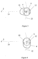
- the drill 4 which is shown in end elevation in Figure 2, is provided with three electromagnetic field sensors in the form of electromagnetic coils 6 mounted with its sensitive or longitudinal axis 8 along the longitudinal axis of the drill centre and coils 10 and 12 which have their sensitive longitudinal axis 14 perpendicular to and offset from the sensitive axis of the first coil 6.
- the coils 10 and 12 are mounted adjacent the external side 16 of the drill at diametrically opposed positions.
- the drill is positioned at the required offset distance from the guidance cable 2 and at the required depth from the surface of the ground 20.
- the sensitive axis 8 of the coil 6 is perpendicular to the flux lines 22 of the magnetic field B as shown in Figure 1. In this position the output signal received from the coil 6 is at its minimum or a null.
- the sensitive axis 8 of the coil 6 remains in its perpendicular position to the flux lines 22 and thus the output signal received from the coil remains in its minimum or a null value.
- the drill changes direction and if this change of direction moves the drill out of the plane 24 such that the length of the drill no longer lies in the plane 24 in end elevation, such movement shown in Figure 4, then the coil 6 intersects a flux line 22 of the magnetic field and the output signal from the coil 6 will increase.
- the output signal from the coil 6 only changes in response to changes in the direction of the drill which moves the longitudinal axis of the drill out of the plane 24 as illustrated in Figure 4.
- the direction and extent of movement of the drill outwith the plane 24 is detected by comparing the output signal received from the coil 6 to the electrical current value applied to the guidance cable 2.
- both the signal received and the electric current are time varying sinusoids, the time relationship between the two, i.e. the phase difference, can be analysed and this allows the direction and plane of the sensitive or longitudinal axis 8 of the coil 6 in the magnetic field B to be determined.
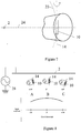
- Figure 5 illustrates in diagrammatic form the manner in which the coil 6 position relative to the guidance cable 2 can have an effect on the output signal received.
- position A the output from the coil is a sinusoid and, when compared to the wave form of the electric current supplied to the guidance cable 2, it can be seen that the output 26 from coil 6 is in phase with the wave form 28 of the electric current supplied to the guidance cable 2.
- position B the output 30 from coil 6 is zero as no flux lines are being cut as the drill lies in the same plane in this position.
- position C the coil 6 has effectively reversed its orientation such that the sensitive axis 8 and hence drill 4 is now pointing away from the guidance cable 2 and thus the output 32 from coil 6 is a sinusoid form which is 180 degrees out of phase with the signal 28.
- the position of the sensitive axis 8 of the coil 6 and hence the longitudinal axis of the drill 4 can be determined by comparison of the output signal 26, 30, 32, or any other output signal received, with the wave form and signal 28 of the guidance cable 2.
- the orientation of the longitudinal axis of the drill 4 relative to the guidance cable 2 and also the rotational orientation of the drill 4 relative to the plane containing the guidance cable and drill can be determined by analysing output signals received of the coils 10 and 12 of the drill.
- the maximum output from the coils 10 and 12 is obtained when the drill is positioned such that the sensitive axis 14 as shown in Figure 2 of the coils 10 and 12 is perpendicular to the plane 24 between the drill and guidance cable as shown in Figure 2 and as illustrated in position A of Figure 6.
- the minimum output from the coils 10 and 12 is obtained when the sensitive axis 14 of the same are parallel to the plane 24 as illustrated in position B of Figure 6 and, if the drill is rotated further, then a maximum negative output signal is received as indicated in position C and a further zero output signal is received at the position shown D.
- a preferred embodiment is to only use one of the coils 10, 12, say coil 10, as this can be rotated to provide the required data.
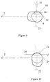
- Figure 9 illustrates the drill 4 in a position where the direction of the same has changed but in the same plane as plane 24 such that the reading from the coil 6 will not alter and, as the rotation is about axis 30, which is perpendicular to the axis 14 of the coil 10, the coil 10 will not be sensitive to orientation changes in or out of the plane.
- the coil 10 is rotated about its sensitive axis 14 but with the coil 10 in the parallel plane to the plane 24 and thus, the output signal for the coil 10 is zero with reference to position B of Figure 6 and as the position of the same does not change relative to the plane 24 no change in signal output will occur but the actual change of the drill 4 upon rotation will be sensed by the change of signal received from the coil 6 with reference to Figure 4, as the drill moves out of the plane 24.
- the coil 10 is positioned in the drill 4 with the sensitive axis 14 aligned parallel to the steering face 32 of the drill 4 as shown in Figure 11, then by rotating the drill 4 and observing output from the coil 10 when rotated until they reach a maximum value, it is possible to orientate the coil 10 and hence the steering face 32 to lie with their planes and plane movement 34 respectively, perpendicular to the plane 24.
- the drill is now pushed forward without rotation and steering corrections can be made to change the direction of the drill perpendicular to the plane 24.
- the output from coil 6 indicates a change in output from the minimum i.e.
- a steering correction can be made by rotating the drill until a maximum is obtained from the coils 10 and 12 and, if the rotation is then stopped at this position the drill can then be pushed forwards to direct the drill 4 back towards the plane 24.
- the positioning is dependent upon the starting position of the drill 4 relative to the guidance cable 2 such that it can be above, below, to the side or any position offset from the guidance cable throughout 360degrees thereof.
- the plane 24 as shown in Figure 12a and 12b can be at any rotational angle R to the horizontal plane and coil 6 is provided to measure deviations from this initial orientation.
- the drill 4 can be subjected to perturbations due to changes in ground conditions as the drill passes therealong and these perturbations can cause the drill 4 to deviate from the plane 24 by an angle S as indicated in Figures 12c and 12d.
- the steering mechanism thus described can bring the drill 4 back into line with the guidance cable 2 but it may be at a different rotational angle R' as indicated in Figure 12f in comparison to the rotational angle R in Figure 12b.
- a roll angle sensor can be provided on the drill which measures the roll angle of the drill relative to the vertical plane.
- Information from one of these sensors, when combined with the information from coils 10 can be used to return the drill to the original rotational angle R in the following manner, whereby if the drill is rotated whilst in the original position, the maximum output from coil 10 is obtained when the roll angle of the drill is at 360-Rdegrees such as that shown in Figure 12b.
- the maximum output from the coil 10 is obtained when the roll angle of the drill is at 360-R'degrees and thus the roll angle at which the maximum value occurs indicates the rotational position of the drill 4 relative to the guidance cable 2.
- the steering system can then be used to return the drill back to the first position as shown in Figure 12a by stopping rotation of the drill when the maximum value is reached and pushing forward the drill to bring the same into the required plane.
- the system is capable of measuring and correcting for deviations in the position of the drill in the plane 24. Because of the shape of the magnetic field B around the guidance cable 2 it is not possible to use the coil 6 to measure angular deviations of the drill 4 in the plane 24 but, by using the coils 10,12 it is possible to measure the distance from the drill 4 to guidance cable 2 by, in one embodiment rotating the drill to the roll angle where a maximum positive output signal is received from the coil 10 and a maximum negative output signal is received from coil 12 comparing the signals to generate a distance value from the guidance plant and then rotating the drill until a maximum negative output signal is received from coil 10 and maximum positive output signal is received from coil 12 and comparing and so on as the drill head progresses.
- FIG. 13 An alternative and preferred arrangement of electromagnetic field sensors or coils is shown in Figure 13, where a coil 106 is provided on drill 104 wherein the coil 106 is provided with its sensitive axis 108 along the longitudinal axis of the drill 104 which lies on a plane 124 defined between a guidance cable 102 and the centre of the drill, in end elevation.
- a coil 110 is positioned offset from the centre of the drill as shown and in this case on the outer surface of the drill with its sensitive axis 114 perpendicular to the longitudinal axis of the drill head.
- Coil 106 is used as described before with reference to coil 6 to measure the deviation of the drill 4 out of the plane 124 and coil 110 is used to measure the relative and rotational position of the drill head 104 with respect to the guidance cable 102.
- the distance of the drill head 104 from the cable 102 is measured using only coil 110 rather than in the previous embodiment where two coils were used. This is achieved by rotating the position of the coil 110, typically by rotating the drill head, and measuring the difference between the output signals from coil 110.
- coil 110 is on the side of the drill 104 nearest to cable 102 as shown, the coil is positioned so that output from the coil will have a maximum positive value V2p and, when the coil 110 is on the side of the drill away from the cable as shown in broken lines 110', it is positioned so that the output has a maximum negative value V2n.
- V2n V2n.S/(V2p - V2n)
- This embodiment has the advantage that it is not necessary for the two coils 10,12 to be used and the same to be matched and calibrated as is the case with the first embodiment wherein matching and calibration is necessary to measure the small differences across the diameter of the drill and the changes in coil parameters which can occur due to temperature and vibration.
- a single coil thus reduces the work needed to set the same up for use and the possible errors which can occur due to temperature and vibration are reduced. Furthermore the space requirements for use of two coils as opposed to three coils and the associated control equipment is significantly less.
- the coils located in the drill are used to detect the magnetic field radiated from the guidance cable.
- the coils used are solenoidal coils and by the selection of the coil orientations and positions it is possible to measure the distance of the drill from the guidance plant and the orientation of the drill relative to the longitudinal axis of the guidance plant and by the use of conventional rotational angle sensors to measure the roll angle of the drill head relative to the vertical plane, in combination with the coils, it is possible to measure the position in the ground of the drill such that the duct formed thereby can be predicted and controlled to be substantially parallel and offset from the guidance cable and thus, a non-intrusive or trenchless duct forming process is provided by the present invention.
- the drill used needs to produce a bore at a nominal separation distance of for example 300 mm from the existing plant with a maximum deviation of plus or minus 100 mm in the bore.
- the accuracy required is achieved by using the location system described herein which continuously detects the position of the existing guidance cable using the detector in the head of the drill and provides the information for either manual or automatic steering adjustment.
- Information from the detector means in the form of output signals are processed directly in the drill chuck to control a steering mechanism in the drill or the information can be passed to the drill operator at the surface where it can be displayed for manual control or to a microprocessor for a computer for automatic control of the drill and in each case, the output signal received from the detector means can then be compared to the input signal along the guidance cable, and so the control of movement of the drill can be achieved.
Landscapes
- Engineering & Computer Science (AREA)
- Geology (AREA)
- Life Sciences & Earth Sciences (AREA)
- Mining & Mineral Resources (AREA)
- Physics & Mathematics (AREA)
- Environmental & Geological Engineering (AREA)
- Fluid Mechanics (AREA)
- General Life Sciences & Earth Sciences (AREA)
- Geochemistry & Mineralogy (AREA)
- Mechanical Engineering (AREA)
- Measurement Of Length, Angles, Or The Like Using Electric Or Magnetic Means (AREA)
- Geophysics And Detection Of Objects (AREA)
- Excavating Of Shafts Or Tunnels (AREA)
Applications Claiming Priority (2)
| Application Number | Priority Date | Filing Date | Title |
|---|---|---|---|
| GBGB9704181.8A GB9704181D0 (en) | 1997-02-28 | 1997-02-28 | Apparatus and method for installation of ducts |
| GB9704181 | 1997-02-28 |
Publications (2)
| Publication Number | Publication Date |
|---|---|
| EP0861966A2 true EP0861966A2 (fr) | 1998-09-02 |
| EP0861966A3 EP0861966A3 (fr) | 2000-09-06 |
Family
ID=10808483
Family Applications (1)
| Application Number | Title | Priority Date | Filing Date |
|---|---|---|---|
| EP98103488A Withdrawn EP0861966A3 (fr) | 1997-02-28 | 1998-02-27 | Dispositif et procédé pour l'installation de conduites et passages souterrains |
Country Status (4)
| Country | Link |
|---|---|
| US (1) | US6102137A (fr) |
| EP (1) | EP0861966A3 (fr) |
| JP (1) | JPH10317884A (fr) |
| GB (1) | GB9704181D0 (fr) |
Cited By (8)
| Publication number | Priority date | Publication date | Assignee | Title |
|---|---|---|---|---|
| EP0913552A3 (fr) * | 1997-10-29 | 2000-05-17 | AT&T Corp. | Procédé et appareil pour l'établissement d'un forage parallèle à un câble souterrain existant |
| US6411094B1 (en) | 1997-12-30 | 2002-06-25 | The Charles Machine Works, Inc. | System and method for determining orientation to an underground object |
| WO2004076799A3 (fr) * | 2003-02-24 | 2004-10-07 | Charles Machine Works | Balise configurable |
| WO2007038940A1 (fr) * | 2005-09-20 | 2007-04-12 | Telecom Italia S.P.A. | Tete de forage, procede et appareil de realisation d’une operation de forage au voisinage d’une bande transporteuse |
| CN109724562A (zh) * | 2019-01-29 | 2019-05-07 | 张亚如 | 一种公路沉降测量装置 |
| CN110700846A (zh) * | 2019-11-05 | 2020-01-17 | 北京住总集团有限责任公司 | 一种基于地质超前探测的盾构机 |
| CN113202976A (zh) * | 2021-05-06 | 2021-08-03 | 上海公路桥梁(集团)有限公司 | 安装于顶管机头后壳体的纠偏推板装置及其纠偏方法 |
| CN114350337A (zh) * | 2021-12-27 | 2022-04-15 | 西安石油大学 | 智能层状纳米稳泡剂及其制备方法和在泡沫驱油中的应用 |
Families Citing this family (41)
| Publication number | Priority date | Publication date | Assignee | Title |
|---|---|---|---|---|
| US7011154B2 (en) | 2000-04-24 | 2006-03-14 | Shell Oil Company | In situ recovery from a kerogen and liquid hydrocarbon containing formation |
| WO2001081720A1 (fr) | 2000-04-24 | 2001-11-01 | Shell Internationale Research Maatschappij B.V. | Recuperation d'hydrocarbures in situ dans une formation contenant du kerogene |
| US7055600B2 (en) | 2001-04-24 | 2006-06-06 | Shell Oil Company | In situ thermal recovery from a relatively permeable formation with controlled production rate |
| CA2668390C (fr) | 2001-04-24 | 2011-10-18 | Shell Canada Limited | Recuperation in situ a partir d'une formation de sables bitumineux |
| US6991032B2 (en) * | 2001-04-24 | 2006-01-31 | Shell Oil Company | In situ thermal processing of an oil shale formation using a pattern of heat sources |
| AU2002303481A1 (en) * | 2001-04-24 | 2002-11-05 | Shell Oil Company | In situ recovery from a relatively low permeability formation containing heavy hydrocarbons |
| WO2003027714A1 (fr) * | 2001-09-25 | 2003-04-03 | Vermeer Manufacturing Company | Architecture d'interface communie pour machines de forage horizontal et systemes de guidage de surface |
| US7090013B2 (en) | 2001-10-24 | 2006-08-15 | Shell Oil Company | In situ thermal processing of a hydrocarbon containing formation to produce heated fluids |
| WO2003036040A2 (fr) | 2001-10-24 | 2003-05-01 | Shell Internationale Research Maatschappij B.V. | Traitement thermique in situ d'une formation chargee en hydrocarbures par utilisation d'une chambre de combustion naturelle distribuee |
| US7077199B2 (en) | 2001-10-24 | 2006-07-18 | Shell Oil Company | In situ thermal processing of an oil reservoir formation |
| US7104319B2 (en) | 2001-10-24 | 2006-09-12 | Shell Oil Company | In situ thermal processing of a heavy oil diatomite formation |
| US7165615B2 (en) | 2001-10-24 | 2007-01-23 | Shell Oil Company | In situ recovery from a hydrocarbon containing formation using conductor-in-conduit heat sources with an electrically conductive material in the overburden |
| DE10225518B4 (de) * | 2002-06-10 | 2004-07-08 | Rayonex Schwingungstechnik Gmbh | Verfahren und Vorrichtung zur Steuerung und Positionsbestimmung eines Instruments oder Gerätes |
| WO2004038175A1 (fr) | 2002-10-24 | 2004-05-06 | Shell Internationale Research Maatschappij B.V. | Procede d'inhibition de la deformation d'un forage lors du traitement thermique in situ d'une formation contenant des hydrocarbures |
| US7121342B2 (en) | 2003-04-24 | 2006-10-17 | Shell Oil Company | Thermal processes for subsurface formations |
| ATE392534T1 (de) | 2004-04-23 | 2008-05-15 | Shell Int Research | Verhinderung von rücklauf in einer beheizten senkung eines in-situ-umwandlungssystems |
| US7986869B2 (en) | 2005-04-22 | 2011-07-26 | Shell Oil Company | Varying properties along lengths of temperature limited heaters |
| US8606091B2 (en) | 2005-10-24 | 2013-12-10 | Shell Oil Company | Subsurface heaters with low sulfidation rates |
| WO2008060668A2 (fr) | 2006-04-21 | 2008-05-22 | Shell Oil Company | Appareils de chauffage à température limitée utilisant la transformation de phase de matériau ferromagnétique |
| US7681647B2 (en) | 2006-10-20 | 2010-03-23 | Shell Oil Company | Method of producing drive fluid in situ in tar sands formations |
| US7861424B2 (en) * | 2006-11-13 | 2011-01-04 | Robert Bosch Tool Corporation | Pipe laser |
| US7841425B2 (en) | 2007-04-20 | 2010-11-30 | Shell Oil Company | Drilling subsurface wellbores with cutting structures |
| CA2700732A1 (fr) | 2007-10-19 | 2009-04-23 | Shell Internationale Research Maatschappij B.V. | Traitement cryogenique de gaz |
| CA2718767C (fr) | 2008-04-18 | 2016-09-06 | Shell Internationale Research Maatschappij B.V. | Utilisation de mines et de tunnels pour le traitement de formations souterraines contenant des hydrocarbures |
| JP2012509418A (ja) | 2008-10-13 | 2012-04-19 | シエル・インターナシヨナル・リサーチ・マートスハツペイ・ベー・ヴエー | 地表下の坑井穴を形成するためのシステムおよび方法 |
| WO2010118315A1 (fr) | 2009-04-10 | 2010-10-14 | Shell Oil Company | Méthodologies de traitement pour des formations souterraines contenant des hydrocarbures |
| US9127523B2 (en) | 2010-04-09 | 2015-09-08 | Shell Oil Company | Barrier methods for use in subsurface hydrocarbon formations |
| US8820406B2 (en) | 2010-04-09 | 2014-09-02 | Shell Oil Company | Electrodes for electrical current flow heating of subsurface formations with conductive material in wellbore |
| US8701769B2 (en) | 2010-04-09 | 2014-04-22 | Shell Oil Company | Methods for treating hydrocarbon formations based on geology |
| US8631866B2 (en) | 2010-04-09 | 2014-01-21 | Shell Oil Company | Leak detection in circulated fluid systems for heating subsurface formations |
| DE102010032134B4 (de) | 2010-07-24 | 2016-09-22 | Tracto-Technik Gmbh & Co. Kg | Verfahren zum Einbringen einer Bohrung in das Erdreich und Erdbohrvorrichtung |
| US9016370B2 (en) | 2011-04-08 | 2015-04-28 | Shell Oil Company | Partial solution mining of hydrocarbon containing layers prior to in situ heat treatment |
| US9309755B2 (en) | 2011-10-07 | 2016-04-12 | Shell Oil Company | Thermal expansion accommodation for circulated fluid systems used to heat subsurface formations |
| CN104428489A (zh) | 2012-01-23 | 2015-03-18 | 吉尼Ip公司 | 地下含烃地层的原位热处理的加热器模式 |
| CA2898956A1 (fr) | 2012-01-23 | 2013-08-01 | Genie Ip B.V. | Motif de rechauffeurs pour un traitement thermique in situ d'une formation a teneur en hydrocarbures de sous-surface |
| RU2648785C2 (ru) * | 2013-12-18 | 2018-03-28 | Хэллибертон Энерджи Сервисиз, Инк. | Волоконно-оптический контроль тока для электромагнитной дальнометрии |
| SG11201608902UA (en) | 2014-05-01 | 2016-11-29 | Halliburton Energy Services Inc | Interwell tomography methods and systems employing a casing segment with at least one transmission crossover arrangement |
| US10309215B2 (en) | 2014-05-01 | 2019-06-04 | Halliburton Energy Services, Inc. | Casing segment having at least one transmission crossover arrangement |
| RU2669416C2 (ru) | 2014-05-01 | 2018-10-11 | Халлибертон Энерджи Сервисез, Инк. | Способы контроля добычи из многоствольной скважины и системы, использующие участок обсадной трубы по меньшей мере с одним устройством передачи и приема данных |
| SG11201608940TA (en) * | 2014-05-01 | 2016-11-29 | Halliburton Energy Services Inc | Guided drilling methods and systems employing a casing segment with at least one transmission crossover arrangement |
| CN115012915B (zh) * | 2022-06-02 | 2023-01-24 | 中国石油天然气集团有限公司 | 基于直导线的磁场定位方法、系统、装置、设备及介质 |
Family Cites Families (9)
| Publication number | Priority date | Publication date | Assignee | Title |
|---|---|---|---|---|
| US3529682A (en) * | 1968-10-03 | 1970-09-22 | Bell Telephone Labor Inc | Location detection and guidance systems for burrowing device |
| US3589454A (en) * | 1968-12-27 | 1971-06-29 | Bell Telephone Labor Inc | Mole guidance system |
| US3907045A (en) * | 1973-11-30 | 1975-09-23 | Continental Oil Co | Guidance system for a horizontal drilling apparatus |
| US4881083A (en) * | 1986-10-02 | 1989-11-14 | Flowmole Corporation | Homing technique for an in-ground boring device |
| US4953638A (en) * | 1988-06-27 | 1990-09-04 | The Charles Machine Works, Inc. | Method of and apparatus for drilling a horizontal controlled borehole in the earth |
| DE3911467A1 (de) * | 1989-04-08 | 1990-10-11 | Tracto Technik | Selbstantreibbares rammbohrgeraet, insbesondere fuer die herstellung von rohrfoermigen erdbohrungen |
| US5320180A (en) * | 1992-10-08 | 1994-06-14 | Sharewell Inc. | Dual antenna radio frequency locating apparatus and method |
| US5589775A (en) * | 1993-11-22 | 1996-12-31 | Vector Magnetics, Inc. | Rotating magnet for distance and direction measurements from a first borehole to a second borehole |
| US5515931A (en) * | 1994-11-15 | 1996-05-14 | Vector Magnetics, Inc. | Single-wire guidance system for drilling boreholes |
-
1997
- 1997-02-28 GB GBGB9704181.8A patent/GB9704181D0/en active Pending
-
1998
- 1998-02-27 US US09/032,669 patent/US6102137A/en not_active Expired - Fee Related
- 1998-02-27 EP EP98103488A patent/EP0861966A3/fr not_active Withdrawn
- 1998-02-27 JP JP10047845A patent/JPH10317884A/ja active Pending
Cited By (11)
| Publication number | Priority date | Publication date | Assignee | Title |
|---|---|---|---|---|
| EP0913552A3 (fr) * | 1997-10-29 | 2000-05-17 | AT&T Corp. | Procédé et appareil pour l'établissement d'un forage parallèle à un câble souterrain existant |
| US6411094B1 (en) | 1997-12-30 | 2002-06-25 | The Charles Machine Works, Inc. | System and method for determining orientation to an underground object |
| US7759824B2 (en) | 1997-12-30 | 2010-07-20 | The Charles Machine Works, Inc. | System and method for detecting an underground object using magnetic field sensing |
| WO2004076799A3 (fr) * | 2003-02-24 | 2004-10-07 | Charles Machine Works | Balise configurable |
| US7624816B2 (en) | 2003-02-24 | 2009-12-01 | The Charles Machine Works, Inc. | Configurable beacon and method |
| WO2007038940A1 (fr) * | 2005-09-20 | 2007-04-12 | Telecom Italia S.P.A. | Tete de forage, procede et appareil de realisation d’une operation de forage au voisinage d’une bande transporteuse |
| CN109724562A (zh) * | 2019-01-29 | 2019-05-07 | 张亚如 | 一种公路沉降测量装置 |
| CN109724562B (zh) * | 2019-01-29 | 2021-01-12 | 长沙理工大学 | 一种公路沉降测量装置 |
| CN110700846A (zh) * | 2019-11-05 | 2020-01-17 | 北京住总集团有限责任公司 | 一种基于地质超前探测的盾构机 |
| CN113202976A (zh) * | 2021-05-06 | 2021-08-03 | 上海公路桥梁(集团)有限公司 | 安装于顶管机头后壳体的纠偏推板装置及其纠偏方法 |
| CN114350337A (zh) * | 2021-12-27 | 2022-04-15 | 西安石油大学 | 智能层状纳米稳泡剂及其制备方法和在泡沫驱油中的应用 |
Also Published As
| Publication number | Publication date |
|---|---|
| GB9704181D0 (en) | 1997-04-16 |
| JPH10317884A (ja) | 1998-12-02 |
| EP0861966A3 (fr) | 2000-09-06 |
| US6102137A (en) | 2000-08-15 |
Similar Documents
| Publication | Publication Date | Title |
|---|---|---|
| US6102137A (en) | Apparatus and method for forming ducts and passageways | |
| JP3466625B2 (ja) | 独立した地中ボーリング機械の位置決め | |
| US5014008A (en) | System for detecting the location and orientation of a temporarily inaccessible object | |
| EP0815472B1 (fr) | Reperage d'objets | |
| EP0357314B1 (fr) | Dispositif pour contrôler la position d'un outil de forage autopropulsé | |
| US6035951A (en) | System for tracking and/or guiding an underground boring tool | |
| US7253628B2 (en) | Tracking the positional relationship between a boring tool and one or more buried lines using a composite magnetic signal | |
| US12259094B2 (en) | Pipeline following sensor arrangement | |
| EP0682270B1 (fr) | Procédé et dispositif pour localiser un élément enterré | |
| US6543550B2 (en) | Long range electronic guidance system for locating a discrete in-ground boring device | |
| KR101562625B1 (ko) | 지하매설관 특정위치 탐지시스템 및 방법 | |
| US20180299575A1 (en) | System For Locating A Utility With A Downhole Beacon | |
| EP2414629B1 (fr) | Système de guidage à deux bobines pour suivre des trous de forage | |
| KR101499173B1 (ko) | 시설물의 위치 및 변위량 측정장치 | |
| GB2254430A (en) | Drilling apparatus | |
| JP3352550B2 (ja) | 位置検出方法 | |
| KR102108794B1 (ko) | 매설된 강 배관의 탐지 장치, 방법 및 컴퓨터로 독출 가능한 기록 매체 | |
| US20180306385A1 (en) | Parallel Utility Installation Apparatus And Method | |
| WO2001046554A1 (fr) | Systeme electronique de guidage longue portee permettant de localiser un dispositif separe de forage souterrain | |
| JPS625117A (ja) | 掘進機の位置検出装置 | |
| JP3553831B2 (ja) | 地中管路の相対方位検出方法及び装置 | |
| GB2243693A (en) | Guiding a tool along a subterranean path | |
| HK1006985B (en) | Device for controlling the position of a self-propelled drilling tool | |
| JPH03123802A (ja) | 埋設管相互の相対位置計測方法 |
Legal Events
| Date | Code | Title | Description |
|---|---|---|---|
| PUAI | Public reference made under article 153(3) epc to a published international application that has entered the european phase |
Free format text: ORIGINAL CODE: 0009012 |
|
| AK | Designated contracting states |
Kind code of ref document: A2 Designated state(s): DE GB NL |
|
| AX | Request for extension of the european patent |
Free format text: AL;LT;LV;MK;RO;SI |
|
| PUAL | Search report despatched |
Free format text: ORIGINAL CODE: 0009013 |
|
| AK | Designated contracting states |
Kind code of ref document: A3 Designated state(s): AT BE CH DE DK ES FI FR GB GR IE IT LI LU MC NL PT SE |
|
| AX | Request for extension of the european patent |
Free format text: AL;LT;LV;MK;RO;SI |
|
| RIC1 | Information provided on ipc code assigned before grant |
Free format text: 7E 21B 7/04 A, 7E 21B 44/00 B, 7E 21B 7/06 B, 7G 01V 3/15 B, 7G 01V 3/10 B, 7E 21B 47/022 B |
|
| 17P | Request for examination filed |
Effective date: 20010301 |
|
| AKX | Designation fees paid |
Free format text: DE GB NL |
|
| 17Q | First examination report despatched |
Effective date: 20021112 |
|
| GRAP | Despatch of communication of intention to grant a patent |
Free format text: ORIGINAL CODE: EPIDOSNIGR1 |
|
| STAA | Information on the status of an ep patent application or granted ep patent |
Free format text: STATUS: THE APPLICATION IS DEEMED TO BE WITHDRAWN |
|
| 18D | Application deemed to be withdrawn |
Effective date: 20040224 |