EP0862009B1 - Lösbare Steckverbindung mit Montageanzeige - Google Patents
Lösbare Steckverbindung mit Montageanzeige Download PDFInfo
- Publication number
- EP0862009B1 EP0862009B1 EP98102351A EP98102351A EP0862009B1 EP 0862009 B1 EP0862009 B1 EP 0862009B1 EP 98102351 A EP98102351 A EP 98102351A EP 98102351 A EP98102351 A EP 98102351A EP 0862009 B1 EP0862009 B1 EP 0862009B1
- Authority
- EP
- European Patent Office
- Prior art keywords
- indicator member
- housing wall
- plug
- opening
- holding rib
- Prior art date
- Legal status (The legal status is an assumption and is not a legal conclusion. Google has not performed a legal analysis and makes no representation as to the accuracy of the status listed.)
- Expired - Lifetime
Links
- 230000008878 coupling Effects 0.000 title 1
- 238000010168 coupling process Methods 0.000 title 1
- 238000005859 coupling reaction Methods 0.000 title 1
- 238000003780 insertion Methods 0.000 claims description 8
- 230000037431 insertion Effects 0.000 claims description 8
- 239000000126 substance Substances 0.000 claims description 2
- 239000012530 fluid Substances 0.000 claims 1
- 230000035515 penetration Effects 0.000 claims 1
- 210000005069 ears Anatomy 0.000 description 2
- 238000004873 anchoring Methods 0.000 description 1
- 238000005452 bending Methods 0.000 description 1
- 238000010276 construction Methods 0.000 description 1
- 238000006073 displacement reaction Methods 0.000 description 1
- 230000000694 effects Effects 0.000 description 1
- 239000000446 fuel Substances 0.000 description 1
- 238000009434 installation Methods 0.000 description 1
- 230000009191 jumping Effects 0.000 description 1
- 239000007788 liquid Substances 0.000 description 1
Images

Classifications
-
- F—MECHANICAL ENGINEERING; LIGHTING; HEATING; WEAPONS; BLASTING
- F16—ENGINEERING ELEMENTS AND UNITS; GENERAL MEASURES FOR PRODUCING AND MAINTAINING EFFECTIVE FUNCTIONING OF MACHINES OR INSTALLATIONS; THERMAL INSULATION IN GENERAL
- F16L—PIPES; JOINTS OR FITTINGS FOR PIPES; SUPPORTS FOR PIPES, CABLES OR PROTECTIVE TUBING; MEANS FOR THERMAL INSULATION IN GENERAL
- F16L37/00—Couplings of the quick-acting type
- F16L37/08—Couplings of the quick-acting type in which the connection between abutting or axially overlapping ends is maintained by locking members
- F16L37/084—Couplings of the quick-acting type in which the connection between abutting or axially overlapping ends is maintained by locking members combined with automatic locking
- F16L37/0841—Couplings of the quick-acting type in which the connection between abutting or axially overlapping ends is maintained by locking members combined with automatic locking by means of a transversally slidable locking member surrounding the tube
-
- F—MECHANICAL ENGINEERING; LIGHTING; HEATING; WEAPONS; BLASTING
- F16—ENGINEERING ELEMENTS AND UNITS; GENERAL MEASURES FOR PRODUCING AND MAINTAINING EFFECTIVE FUNCTIONING OF MACHINES OR INSTALLATIONS; THERMAL INSULATION IN GENERAL
- F16L—PIPES; JOINTS OR FITTINGS FOR PIPES; SUPPORTS FOR PIPES, CABLES OR PROTECTIVE TUBING; MEANS FOR THERMAL INSULATION IN GENERAL
- F16L2201/00—Special arrangements for pipe couplings
- F16L2201/10—Indicators for correct coupling
-
- Y—GENERAL TAGGING OF NEW TECHNOLOGICAL DEVELOPMENTS; GENERAL TAGGING OF CROSS-SECTIONAL TECHNOLOGIES SPANNING OVER SEVERAL SECTIONS OF THE IPC; TECHNICAL SUBJECTS COVERED BY FORMER USPC CROSS-REFERENCE ART COLLECTIONS [XRACs] AND DIGESTS
- Y10—TECHNICAL SUBJECTS COVERED BY FORMER USPC
- Y10S—TECHNICAL SUBJECTS COVERED BY FORMER USPC CROSS-REFERENCE ART COLLECTIONS [XRACs] AND DIGESTS
- Y10S285/00—Pipe joints or couplings
- Y10S285/921—Snap-fit
Definitions
- the invention relates to a detachable connector with a display for connecting pipes for liquid and gaseous substances after the Preamble of claim 1.
- the display part consists of two, fork-shaped on a flag part, to each other parallel webs, which in two opposite side slots of the Housing wall can be inserted tangentially and in the receiving area of the retaining rib have two ears protruding inwards, which when inserting the Push the insert from the holding rib to the outside. Show the ears further towards the fork bracket each have a locking hook, which is inserted in the Check the condition of the display part at the end of the side slot. As soon as the Fork webs are pushed apart by the holding rib, the also loosen Snap hooks from the longitudinal slots and the display part can be on the outside protruding flag can be pulled out as proof of assembly.
- the protruding outside Flag always has the same position before and after assembly and only pulling the flag can determine whether the display part is coming loose lets and the holding rib of the insert part thus on the locking edges of the holding part is engaged.
- the object of the invention is to design the display part so that when correct Installation of the plug-in connection, the completion report is carried out automatically without the fitter still has to carry out an additional handle.
- the display part made of resiliently compressible V-shaped merging in the radial plane Webs exist, which in the pressed state of the display part with outwardly protruding projections in the opening of the housing wall are snap-button-like, with the webs on their out of the opening projecting end are connected to a spring-loaded tab, which its opposite end is designed to be anchored to the housing wall.
- a clamp For anchoring the display part on the plug housing is at the free end of the tab expediently formed a clamp, which in a corresponding circumferential groove can be inserted into the housing wall.
- the tab Clamp according to the invention aligned so that it with the display part in in the relaxed state protrudes radially outwards and in the pressed state the display part exerts a radially outward force.
- the Snap-like latching effect can be achieved through the design of the Realize display part according to claim 5 particularly easily.
- the plug connection shown in the figures is used for the detachable connection of pipelines and in particular of fuel lines in motor vehicle construction.
- the plug-in connection here consists of a cylindrical plug-in housing 1, a tubular plug-in part 2 with a circumferential retaining rib 3 and a display part 4 which can be connected to the plug-in housing 1 .
- the plug-in housing 1 has in its plug-in area a receiving space 5 for a separate holding element 6 , which is inserted from the outside transversely to the housing axis through a corresponding recess 7 in the housing wall 8 in the direction of arrow Z.
- This holding element 6 as can be seen from FIGS. 5 and 6 , has support bodies 9 with radially inwardly directed latching edges 10, which are intended to engage behind the holding rib 3 after the insertion part 2 has been pressed into the plug housing 1 and to hold it in the closed position ( FIG 8 ).
- the support bodies 9 are connected to one another on one side via V-shaped spring webs 11 and a rounded connection point 14 and on the other side via likewise V-shaped spring webs 12 connected to a pressure plate 13 .
- the display part 4 shown in Figures 1, 3 and 4 consists of two V-shaped merged resiliently compressible ribs 15 which are integrally formed on the underside of a support tab 17 roof-shaped and are connected at their free ends by a transverse web sixteenth
- the support tab 17 is connected in the middle to a tab 18 , at the end of which a clamp 19 is formed.
- This clamp 19 is designed in the inside diameter and in the width so that it can be inserted into a corresponding circumferential groove 20 in the housing wall 8 and anchored there.
- the display part 4 is anchored to the housing wall 8 so that the tab 18 with the support tab 17 protrudes radially outward in the relaxed state and exerts a radially outward pulling force P after the pivoting of the display part 4 in the direction of arrow E by the applied bending stress .
- the webs 15 as can be seen from FIGS. 2 and 4 , have outwardly projecting projections 21, which can be locked in the opening 22 of the housing wall 8 in the pressed-in state of the display part 6 .
- This opening 22 is located in the insertion direction of the insertion part 2 behind the locking edges 10 of the holding element 6 and, as can be clearly seen in FIG. 2 in the lower region of the housing wall 8 with the same opening 22 , has a width B which corresponds to the outer distance A of the corresponds to the two spring bars 15 just below the support tab 17 .
- the support body 9 of the holding element 6 have at the same point below the opening 22 a recess 25 corresponding to the width and thickness of the spring bars 15, so that it can be inserted in the insertion direction behind the support bodies 9 into the receiving area of the holding rib 3 .
- the spring bars 15 run from the underside of the support tab 17 in a length corresponding to the wall thickness of the housing wall 8 initially approximately parallel to one another and then widen conically up to the projections 21 , in order then to converge again in a V-shape to the cross bar 16 .
- This cross web 16 is slanted corresponding to the radial extent of the holding rib 3 in the insertion direction of the plug 2 by a surface 24, the height h of the conical expansion until the projection 21 of the radial extension of the inclined surface 24 corresponds to b.
- the plug-in part 2 is now pressed into the plug connection housing 1 in the direction of the arrow M , the latching edges 10 of the holding part 6 are first pressed apart by the holding rib 3 .
- the holding rib 3 then abuts against the inclined surface 24 of the transverse web 16 and pushes it outwards together with the display part 4 by the radially acting force component.
- the spring bars 15 are elastically compressed through the opening 22 until the projections 21 have passed the inner opening edge 23 .
- the support tab 17 with the spring bars 15 is pulled outwards due to the tensile force P released by the pretensioned tabs 18 .
- the support tab 17 rises like a flag over the connector housing 1 and thus indicates that the plug-in part 2 is correctly mounted ( Figure 8).
Landscapes
- Engineering & Computer Science (AREA)
- General Engineering & Computer Science (AREA)
- Mechanical Engineering (AREA)
- Quick-Acting Or Multi-Walled Pipe Joints (AREA)
- Details Of Connecting Devices For Male And Female Coupling (AREA)
Description
- Fig. 1
- ein Steckverbindungsgehäuse mit montiertem Anzeigeteil im Schnitt nach Linie I-I in Fig. 2,
- Fig. 2
- einen Querschnitt durch das Gehäuse gemäß Linie II-II in Fig. 1 mit eingerastetem Anzeigeteil,
- Fig. 3
- das Anzeigeteil nach der Erfindung im ungespannten Zustand,
- Fig. 4
- eine Teilansicht des Anzeigeteils nach Fig. 3 im gespannten Zustand in Montageposition über der Öffnung des Steckgehäuses vor dem Einrasten
- Fig. 5
- ein Halteelement in Draufsicht in Montageposition vor dem Einführen in die Aussparung der Gehäusewand,
- Fig. 6
- das gleiche Halteelement in Seitenansicht,
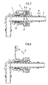
- Fig. 7
- ein Steckverbindungsgehäuse mit montiertem Anzeigeteil beim Einführen eines Einsteckteils vor dem Einrasten der Halterippe und
- Fig. 8
- die gleiche Montagesituation nach dem Einrasten der Halterippe mit Anzeige der korrekten Montage.
Claims (5)
- Lösbare Steckverbindung mit Montageanzeige zum Verbinden von Leitungen für flüssige und gasförmige Stoffe, bestehend aus einem mit dem Ende der einen Rohrleitung verbindbaren, rohrförmigen Einsteckteil (2) mit einer umlaufenden Halterippe ( 3 ), einem mit dem Ende der anderen Rohrleitung verbindbaren, zylindrischen Steckgehäuse ( 1 ) mit einem Aufnahmeraum ( 5 ) für ein separates Halteelement ( 6 ) mit radial nach innen gerichteten, elastisch auffederbaren Rastkanten ( 10) zum Hintergreifen der Halterippe ( 3 ) nach dem Eindrücken des Einsteckteils ( 2 ) sowie aus einem Anzeigeteil ( 4 ), welches in Einsteckrichtung hinter den Rastkanten ( 10) des Halteelements ( 6 ) radial in den Aufnahmeraum (5) bis in den Aufnahmebereich der Halterippe ( 3 ) hineinragt und in Einsteckrichtung entsprechend der radialen Erstreckung der Halterippe ( 3 ) derart abgeschrägt ist, daß das Anzeigeteil ( 4 ) nach vollständigem Eindringen der Halterippe ( 3) von dieser verdrängt wird, dadurch gekennzeichnet, daß das Anzeigeteil ( 4) aus in der Radialebene V-förmig zusammengeführten, federnd zusammendrückbaren Stegen ( 15 ) besteht, welche am unteren Ende durch einen eine Schrägfläche ( 24 ) aufweisenden Quersteg ( 16 ) miteinander verbunden und im eingedrückten Zustand des Anzeigeteils ( 4 ) mit nach außen abstehenden Vorsprüngen ( 21 ) in einer Öffnung ( 22 ) der Gehäusewand ( 8 ) druckknopfartig verrastbar sind, wobei die Stege (15) an ihrem aus der Öffnung ( 22 ) vorstehenden Ende mit einer auffederbaren Lasche ( 18 ) verbunden sind, welche an ihrem entgegengesetzten Ende am Steckgehäuse (1) verankerbar ausgebildet ist.
- Lösbare Steckverbindung nach Anspruch 1, dadurch gekennzeichnet, daß an dem freien Ende der Lasche ( 18) eine Klemmschelle ( 19) angeformt ist, welche in eine entsprechende umlaufende Nut ( 20 ) in der Gehäusewand ( 8) einsteckbar ist.
- Lösbare Steckverbindung nach Anspruch 1 oder 2 , dadurch gekennzeichnet, daß die Lasche ( 18) mit dem Anzeigeteil ( 4 ) im entspannten Zustand radial nach außen absteht und im eingedrückten Zustand auf das Anzeigeteil ( 4 ) eine radial nach außen gerichtete Zugkraft ( P ) ausübt.
- Lösbare Steckverbindung nach einem der Ansprüche 1 bis 3, dadurch gekennzeichnet, daß das Anzeigeteil ( 4 ) beiderseits der Öffnung ( 22 ) mit auf der Gehäusewand ( 8 ) federnd aufliegenden Lappen (17) abgestützt ist.
- Lösbare Steckverbindung nach einem der Ansprüche 1 bis 4, dadurch gekennzeichnet, daß die Federstege (15) entsprechend der Breite ( B ) der Öffnung ( 22 ) und der Dicke der Gehäusewand ( 8 ) vom Lappen ( 17 ) aus zunächst parallel verlaufen und in dem sich nach innen anschließenden Bereich bis zu den Vorsprüngen ( 21 ) konisch auseinanderlaufen, wobei die Höhe ( h ) der konischen Erweiterung bis zum Vorsprung ( 21 ) gleich der radialen Erstreckung ( b ) der Schrägfläche ( 24) am unteren Quersteg (16) der Federstege ( 15 ) ist.
Applications Claiming Priority (2)
| Application Number | Priority Date | Filing Date | Title |
|---|---|---|---|
| DE19708377 | 1997-03-01 | ||
| DE19708377A DE19708377C1 (de) | 1997-03-01 | 1997-03-01 | Lösbare Steckverbindung mit Montageanzeige |
Publications (2)
| Publication Number | Publication Date |
|---|---|
| EP0862009A1 EP0862009A1 (de) | 1998-09-02 |
| EP0862009B1 true EP0862009B1 (de) | 2001-09-26 |
Family
ID=7821952
Family Applications (1)
| Application Number | Title | Priority Date | Filing Date |
|---|---|---|---|
| EP98102351A Expired - Lifetime EP0862009B1 (de) | 1997-03-01 | 1998-02-11 | Lösbare Steckverbindung mit Montageanzeige |
Country Status (6)
| Country | Link |
|---|---|
| US (1) | US6082779A (de) |
| EP (1) | EP0862009B1 (de) |
| JP (1) | JP4065570B2 (de) |
| DE (1) | DE19708377C1 (de) |
| ES (1) | ES2165106T3 (de) |
| WO (1) | WO1998038450A1 (de) |
Families Citing this family (44)
| Publication number | Priority date | Publication date | Assignee | Title |
|---|---|---|---|---|
| DE19722842C2 (de) * | 1997-05-30 | 2001-04-12 | Raymond A & Cie | Lösbare Schnellkupplung |
| DE19923636A1 (de) * | 1999-05-22 | 2000-11-23 | Murrplastik Systemtechnik Gmbh | Verschraubung |
| KR100331471B1 (ko) * | 1999-11-16 | 2002-04-09 | 황현식 | 차량용 연료관의 컨넥터 |
| GB0011317D0 (en) * | 2000-05-10 | 2000-06-28 | John Guest International Limit | Tube couplings |
| DE10025817C2 (de) * | 2000-05-24 | 2002-06-20 | Raymond A & Cie | Lösbare Schnellkupplung mit Sicherheitsverrastung |
| DE50004661D1 (de) * | 2000-09-20 | 2004-01-15 | Ti Automotive Fuldabrueck Gmbh | Kupplung, insbesondere Schnellkupplung, für Kraftstoffrohrleitungsabschnitte |
| US6688654B2 (en) * | 2000-12-08 | 2004-02-10 | Newfrey Llc | One piece quick connector |
| FR2818731B1 (fr) * | 2000-12-22 | 2006-11-03 | Legris Sa | Coupleur rapide avec temoin de connexion |
| DE10115399C1 (de) * | 2001-03-29 | 2002-06-06 | Raymond A & Cie | Lösbare Steckverbindung mit zusätzlichem Verriegelungselement |
| DE10126205C1 (de) * | 2001-05-30 | 2002-04-04 | Raymond A & Cie | Lösbare Steckkupplung mit Schutzhülse |
| FR2829829B1 (fr) * | 2001-09-20 | 2004-02-13 | Legris Sa | Dispositif de raccordement a montage securise |
| JP3988180B2 (ja) * | 2002-02-28 | 2007-10-10 | 東海ゴム工業株式会社 | 接続確認機能付きクイックコネクタ |
| DE10219442B4 (de) * | 2002-05-02 | 2010-09-16 | Mann + Hummel Gmbh | Steckverbindung |
| US7316428B2 (en) * | 2002-10-07 | 2008-01-08 | Tokai Rubber Industries, Ltd. | Connection verifying device and connection verifying structure for a pipe and a connector |
| FR2847647B1 (fr) * | 2002-11-25 | 2007-10-05 | Raccord a securite augmentee | |
| US6810569B1 (en) | 2003-07-08 | 2004-11-02 | Visteon Global Technologies, Inc. | Workpiece release with computer verified connections |
| US7390025B2 (en) * | 2004-03-31 | 2008-06-24 | Ti Group Automotive Systems, Llc | Secondary latch/verifier for a quick connector |
| US20050236833A1 (en) * | 2004-04-23 | 2005-10-27 | Poirier David M | Tube lock quick connector |
| DE102004052475A1 (de) * | 2004-10-28 | 2006-05-04 | Eaton Fluid Power Gmbh | Zugfeste Steckkupplung |
| DE102004062207B3 (de) * | 2004-12-23 | 2005-10-20 | Kirchner Fraenk Rohr | Verbindungseinrichtung |
| GB2428278B (en) * | 2005-07-09 | 2010-03-17 | Ford Global Tech Llc | A fluid connector assembly |
| FR2891344B1 (fr) * | 2005-09-29 | 2009-04-10 | Hutchinson Sa | Raccord encliquetable entre un conduit de fluide et un embout tubulaire rigide. |
| FR2891889B1 (fr) * | 2005-10-07 | 2009-03-06 | Caillau Ets | Embout de connexion etanche et piece terminale pour un tel embout |
| DE102005055549B4 (de) * | 2005-11-18 | 2010-05-12 | A. Raymond & Cie | Kupplung |
| DE102005056777B3 (de) * | 2005-11-28 | 2006-11-30 | Rasmussen Gmbh | Steckkupplung zum Verbinden zweier Fluidleitungen |
| US7497480B2 (en) * | 2006-04-07 | 2009-03-03 | Ti Group Automotive Systems, Llc | Hybrid quick connector |
| DE102006017816B4 (de) * | 2006-04-13 | 2008-04-24 | Eaton Fluid Power Gmbh | Innerer Kältemaschinen-Wärmetauscher |
| DE102006047267B4 (de) * | 2006-10-04 | 2010-02-04 | A. Raymond Et Cie | Kupplungsteil für eine Fluidleitungskupplung |
| US7699356B2 (en) * | 2007-05-10 | 2010-04-20 | Craig Assgembly, Inc. | Quick connector for fluid conduit |
| FR2919372B1 (fr) * | 2007-07-25 | 2013-05-10 | Legris Sa | Raccord a temoin. |
| WO2011140280A2 (en) * | 2010-05-04 | 2011-11-10 | Douglas Milton Fansler | Quick connector assembly |
| DE102010048107A1 (de) * | 2010-10-09 | 2012-04-12 | Norma Germany Gmbh | Verbindungselement für eine Fluidverbindung |
| EP2715204A2 (de) | 2011-06-02 | 2014-04-09 | A. Raymond et Cie | Durch dreidimensionales drucken hergestellte verbinder |
| US8967209B2 (en) * | 2012-03-29 | 2015-03-03 | Superior Power Tool Co., Ltd. | Adapter structure for a gas fuel bottle |
| CA2929476C (en) * | 2013-11-06 | 2019-01-22 | Becton Dickinson and Company Limited | System for closed transfer of fluids with a locking member |
| US9528644B2 (en) * | 2013-12-12 | 2016-12-27 | Zoje Kitchen & Bath Co. Ltd. | Quick connector assembly |
| DE102015109581A1 (de) | 2015-06-16 | 2016-12-22 | Johannes Schäfer vorm. Stettiner Schraubenwerke GmbH & Co. KG | Steckverbindung für Rohrleitungen mit Verbindungsanzeige |
| JP6509149B2 (ja) * | 2016-03-02 | 2019-05-08 | 株式会社ニフコ | 管状体のロック機構 |
| DE102017001396B4 (de) * | 2017-02-14 | 2025-10-23 | Uniwell Rohrsysteme Gmbh & Co. Kg | Schnellverbindungsvorrichtung, Schnellverbindungssystem und Herstellungsverfahren |
| WO2018216143A1 (ja) * | 2017-05-24 | 2018-11-29 | 株式会社ニフコ | 管状体のロック機構 |
| US11199281B2 (en) | 2018-01-31 | 2021-12-14 | A. Raymond Et Cie. | Dual-latch quick connector |
| DE102018219440A1 (de) | 2018-11-14 | 2020-05-14 | Fränkische Industrial Pipes GmbH & Co. KG | Verbindungseinheit |
| KR102520517B1 (ko) * | 2021-06-10 | 2023-04-17 | 부국산업주식회사 | 모니터링 창이 형성된 퀵 커넥터 |
| MX2024001791A (es) * | 2021-08-13 | 2024-02-28 | Dlhbowles Inc | Montaje de conector vda con verificacion. |
Family Cites Families (8)
| Publication number | Priority date | Publication date | Assignee | Title |
|---|---|---|---|---|
| US4753458A (en) * | 1986-08-28 | 1988-06-28 | Harvard Industries, Inc. | Quick connector assembly |
| JP2691550B2 (ja) * | 1988-03-01 | 1997-12-17 | 臼井国際産業株式会社 | 細径配管接続用コネクター |
| JPH0538318Y2 (de) * | 1988-03-08 | 1993-09-28 | ||
| FR2636714B1 (fr) * | 1988-09-21 | 1991-01-25 | Hutchinson | Dispositif de raccord rapide, en particulier pour des conduits de fluide dans un vehicule automobile |
| US5152555A (en) * | 1991-03-26 | 1992-10-06 | Itt Corporation | Quick connect insertion indicator clip |
| DE4300037C1 (de) | 1993-01-02 | 1994-04-21 | Raymond A & Cie | Lösbare Steckverbindung |
| US5395140A (en) * | 1993-05-13 | 1995-03-07 | Enhanced Applications, L.C. | Secondary latch and indicator for fluid coupling |
| FR2705431B1 (fr) * | 1993-05-14 | 1995-07-13 | Legris Sa | Connecteur rapide avec dispositif indicateur. |
-
1997
- 1997-03-01 DE DE19708377A patent/DE19708377C1/de not_active Expired - Fee Related
-
1998
- 1998-02-11 ES ES98102351T patent/ES2165106T3/es not_active Expired - Lifetime
- 1998-02-11 EP EP98102351A patent/EP0862009B1/de not_active Expired - Lifetime
- 1998-02-12 JP JP53723798A patent/JP4065570B2/ja not_active Expired - Fee Related
- 1998-02-12 WO PCT/EP1998/000795 patent/WO1998038450A1/de not_active Ceased
- 1998-02-27 US US09/032,573 patent/US6082779A/en not_active Expired - Fee Related
Also Published As
| Publication number | Publication date |
|---|---|
| DE19708377C1 (de) | 1998-06-18 |
| WO1998038450A1 (de) | 1998-09-03 |
| US6082779A (en) | 2000-07-04 |
| JP4065570B2 (ja) | 2008-03-26 |
| JP2001513174A (ja) | 2001-08-28 |
| ES2165106T3 (es) | 2002-03-01 |
| EP0862009A1 (de) | 1998-09-02 |
Similar Documents
| Publication | Publication Date | Title |
|---|---|---|
| EP0862009B1 (de) | Lösbare Steckverbindung mit Montageanzeige | |
| EP0965014B1 (de) | Verbindungs- und anschlussstück für wellrohre | |
| EP1845299B1 (de) | Anschlussvorrichtung für ein Rohr | |
| EP0959290B1 (de) | Lösbare Schnellkupplung mit automatischer Montageanzeige | |
| DE102006019257B4 (de) | Fluidleitungskupplung | |
| EP0906534B1 (de) | Lösbare steckverbindung mit montageanzeige | |
| DE10250421A1 (de) | Verbindungselement | |
| CH667139A5 (de) | Verbindungsbeschlag. | |
| DE19536316C1 (de) | Klammer zur Halterung von Rohren | |
| EP1318343A2 (de) | Steckverbindung | |
| EP1557600B1 (de) | Steckkupplung zum Anschliessen einer Fluidleitung an einem Rohr | |
| EP2198170B1 (de) | Vorrichtung zum befestigen eines anbauteiles an einem trägerteil | |
| DE10025817C2 (de) | Lösbare Schnellkupplung mit Sicherheitsverrastung | |
| EP1969280B1 (de) | Steckteil für steckverbinderanordnung | |
| DE10059522A1 (de) | Klammersystem zur Befestigung eines Anbauteils auf einem Trägerteil | |
| DE10322124A1 (de) | Vorrichtung zur Bestimmung wenigstens eines Parameters eines in einer Leitung strömenden Mediums | |
| DE3346423A1 (de) | Rohrschelle | |
| DE3705610A1 (de) | Loesbare steckverbindung fuer rohrleitungen | |
| DE4217646C1 (en) | Push in connector for two pipe sections - has coaxially interfitting connectors with spring clip locked even in release position on one part by locking element with detent allowing pre-fitting | |
| DE102009037304A1 (de) | Kraftfahrzeugklimaanlage | |
| EP3153757B1 (de) | Lösbare steckverbindung für rohrleitungen | |
| EP1790899B1 (de) | Steckkupplung zum Verbinden zweier Fluidleitungen | |
| DE19932744C2 (de) | Federelement zur lösbaren Verbindung eines Gabelkopfs mit einem Lagerzapfen | |
| DE3901104C2 (de) | Verbindungsstecker mit Rastfunktion für fluidführende Leitungen | |
| DE8700415U1 (de) | Rohrverschraubung |
Legal Events
| Date | Code | Title | Description |
|---|---|---|---|
| PUAI | Public reference made under article 153(3) epc to a published international application that has entered the european phase |
Free format text: ORIGINAL CODE: 0009012 |
|
| AK | Designated contracting states |
Kind code of ref document: A1 Designated state(s): ES FR GB IT |
|
| AX | Request for extension of the european patent |
Free format text: AL;LT;LV;MK;RO;SI |
|
| 17P | Request for examination filed |
Effective date: 19990302 |
|
| AKX | Designation fees paid |
Free format text: ES FR GB IT |
|
| RBV | Designated contracting states (corrected) |
Designated state(s): ES FR GB IT |
|
| REG | Reference to a national code |
Ref country code: DE Ref legal event code: 8566 |
|
| GRAG | Despatch of communication of intention to grant |
Free format text: ORIGINAL CODE: EPIDOS AGRA |
|
| GRAG | Despatch of communication of intention to grant |
Free format text: ORIGINAL CODE: EPIDOS AGRA |
|
| GRAH | Despatch of communication of intention to grant a patent |
Free format text: ORIGINAL CODE: EPIDOS IGRA |
|
| 17Q | First examination report despatched |
Effective date: 20010223 |
|
| GRAH | Despatch of communication of intention to grant a patent |
Free format text: ORIGINAL CODE: EPIDOS IGRA |
|
| GRAA | (expected) grant |
Free format text: ORIGINAL CODE: 0009210 |
|
| AK | Designated contracting states |
Kind code of ref document: B1 Designated state(s): ES FR GB IT |
|
| ET | Fr: translation filed | ||
| REG | Reference to a national code |
Ref country code: GB Ref legal event code: IF02 |
|
| GBT | Gb: translation of ep patent filed (gb section 77(6)(a)/1977) |
Effective date: 20011201 |
|
| REG | Reference to a national code |
Ref country code: ES Ref legal event code: FG2A Ref document number: 2165106 Country of ref document: ES Kind code of ref document: T3 |
|
| PLBE | No opposition filed within time limit |
Free format text: ORIGINAL CODE: 0009261 |
|
| STAA | Information on the status of an ep patent application or granted ep patent |
Free format text: STATUS: NO OPPOSITION FILED WITHIN TIME LIMIT |
|
| 26N | No opposition filed | ||
| PGFP | Annual fee paid to national office [announced via postgrant information from national office to epo] |
Ref country code: ES Payment date: 20030127 Year of fee payment: 6 |
|
| PGFP | Annual fee paid to national office [announced via postgrant information from national office to epo] |
Ref country code: GB Payment date: 20030210 Year of fee payment: 6 |
|
| PGFP | Annual fee paid to national office [announced via postgrant information from national office to epo] |
Ref country code: FR Payment date: 20040210 Year of fee payment: 7 |
|
| PG25 | Lapsed in a contracting state [announced via postgrant information from national office to epo] |
Ref country code: GB Free format text: LAPSE BECAUSE OF NON-PAYMENT OF DUE FEES Effective date: 20040211 |
|
| PG25 | Lapsed in a contracting state [announced via postgrant information from national office to epo] |
Ref country code: ES Free format text: LAPSE BECAUSE OF NON-PAYMENT OF DUE FEES Effective date: 20040212 |
|
| GBPC | Gb: european patent ceased through non-payment of renewal fee |
Effective date: 20040211 |
|
| PG25 | Lapsed in a contracting state [announced via postgrant information from national office to epo] |
Ref country code: IT Free format text: LAPSE BECAUSE OF NON-PAYMENT OF DUE FEES Effective date: 20050211 |
|
| REG | Reference to a national code |
Ref country code: ES Ref legal event code: FD2A Effective date: 20040212 |
|
| PG25 | Lapsed in a contracting state [announced via postgrant information from national office to epo] |
Ref country code: FR Free format text: LAPSE BECAUSE OF NON-PAYMENT OF DUE FEES Effective date: 20051031 |
|
| REG | Reference to a national code |
Ref country code: FR Ref legal event code: ST Effective date: 20051031 |