EP0862016B1 - Vorrichtung zur Beleuchtung von mindestens einem Wasserstrahls - Google Patents
Vorrichtung zur Beleuchtung von mindestens einem Wasserstrahls Download PDFInfo
- Publication number
- EP0862016B1 EP0862016B1 EP98400212A EP98400212A EP0862016B1 EP 0862016 B1 EP0862016 B1 EP 0862016B1 EP 98400212 A EP98400212 A EP 98400212A EP 98400212 A EP98400212 A EP 98400212A EP 0862016 B1 EP0862016 B1 EP 0862016B1
- Authority
- EP
- European Patent Office
- Prior art keywords
- water
- water supply
- lens
- light
- jet
- Prior art date
- Legal status (The legal status is an assumption and is not a legal conclusion. Google has not performed a legal analysis and makes no representation as to the accuracy of the status listed.)
- Expired - Lifetime
Links
- XLYOFNOQVPJJNP-UHFFFAOYSA-N water Substances O XLYOFNOQVPJJNP-UHFFFAOYSA-N 0.000 title claims description 124
- 230000003287 optical effect Effects 0.000 claims description 21
- 239000004020 conductor Substances 0.000 claims description 9
- 239000012780 transparent material Substances 0.000 claims description 9
- 230000015572 biosynthetic process Effects 0.000 claims description 6
- 238000011144 upstream manufacturing Methods 0.000 claims description 5
- 239000007787 solid Substances 0.000 claims description 4
- 230000000295 complement effect Effects 0.000 claims description 3
- 239000013307 optical fiber Substances 0.000 description 17
- 229920000297 Rayon Polymers 0.000 description 7
- 239000002964 rayon Substances 0.000 description 7
- 229920003023 plastic Polymers 0.000 description 5
- 238000011161 development Methods 0.000 description 4
- 230000018109 developmental process Effects 0.000 description 4
- 239000011521 glass Substances 0.000 description 4
- 238000009434 installation Methods 0.000 description 4
- 239000000463 material Substances 0.000 description 4
- 239000004033 plastic Substances 0.000 description 4
- 238000005286 illumination Methods 0.000 description 3
- 208000031968 Cadaver Diseases 0.000 description 2
- 239000007788 liquid Substances 0.000 description 2
- 230000006978 adaptation Effects 0.000 description 1
- 230000001174 ascending effect Effects 0.000 description 1
- 239000000470 constituent Substances 0.000 description 1
- 238000010276 construction Methods 0.000 description 1
- 230000007423 decrease Effects 0.000 description 1
- 238000006073 displacement reaction Methods 0.000 description 1
- 230000000694 effects Effects 0.000 description 1
- -1 for example Substances 0.000 description 1
- 238000012986 modification Methods 0.000 description 1
- 230000004048 modification Effects 0.000 description 1
- 238000000926 separation method Methods 0.000 description 1
- 210000003462 vein Anatomy 0.000 description 1
Images

Classifications
-
- E—FIXED CONSTRUCTIONS
- E03—WATER SUPPLY; SEWERAGE
- E03C—DOMESTIC PLUMBING INSTALLATIONS FOR FRESH WATER OR WASTE WATER; SINKS
- E03C1/00—Domestic plumbing installations for fresh water or waste water; Sinks
- E03C1/02—Plumbing installations for fresh water
- E03C1/04—Water-basin installations specially adapted to wash-basins or baths
- E03C1/0408—Water installations especially for showers
-
- F—MECHANICAL ENGINEERING; LIGHTING; HEATING; WEAPONS; BLASTING
- F21—LIGHTING
- F21S—NON-PORTABLE LIGHTING DEVICES; SYSTEMS THEREOF; VEHICLE LIGHTING DEVICES SPECIALLY ADAPTED FOR VEHICLE EXTERIORS
- F21S8/00—Lighting devices intended for fixed installation
-
- F—MECHANICAL ENGINEERING; LIGHTING; HEATING; WEAPONS; BLASTING
- F21—LIGHTING
- F21V—FUNCTIONAL FEATURES OR DETAILS OF LIGHTING DEVICES OR SYSTEMS THEREOF; STRUCTURAL COMBINATIONS OF LIGHTING DEVICES WITH OTHER ARTICLES, NOT OTHERWISE PROVIDED FOR
- F21V33/00—Structural combinations of lighting devices with other articles, not otherwise provided for
- F21V33/0004—Personal or domestic articles
- F21V33/004—Sanitary equipment, e.g. mirrors, showers, toilet seats or paper dispensers
-
- F—MECHANICAL ENGINEERING; LIGHTING; HEATING; WEAPONS; BLASTING
- F21—LIGHTING
- F21V—FUNCTIONAL FEATURES OR DETAILS OF LIGHTING DEVICES OR SYSTEMS THEREOF; STRUCTURAL COMBINATIONS OF LIGHTING DEVICES WITH OTHER ARTICLES, NOT OTHERWISE PROVIDED FOR
- F21V2200/00—Use of light guides, e.g. fibre optic devices, in lighting devices or systems
- F21V2200/10—Use of light guides, e.g. fibre optic devices, in lighting devices or systems of light guides of the optical fibres type
- F21V2200/13—Use of light guides, e.g. fibre optic devices, in lighting devices or systems of light guides of the optical fibres type the light being emitted at the end of the guide
-
- F—MECHANICAL ENGINEERING; LIGHTING; HEATING; WEAPONS; BLASTING
- F21—LIGHTING
- F21W—INDEXING SCHEME ASSOCIATED WITH SUBCLASSES F21K, F21L, F21S and F21V, RELATING TO USES OR APPLICATIONS OF LIGHTING DEVICES OR SYSTEMS
- F21W2121/00—Use or application of lighting devices or systems for decorative purposes, not provided for in codes F21W2102/00 – F21W2107/00
- F21W2121/02—Use or application of lighting devices or systems for decorative purposes, not provided for in codes F21W2102/00 – F21W2107/00 for fountains
Definitions
- the present invention relates to a device for making luminous water jets as well as installations equipped with such a device, such as, for example, fountains, shower facilities or even cascades.
- a device of this type is known from GB-A-2 288 974.
- patent FR-A-2 562 637 belonging to the applicants of the present application, discloses a device for making luminous water jets which comprises, for each jet to be illuminated, a light conductor such that a or a plurality of optical fibers, connected to a light source. The output end of the conductor whose cross section is small relative to the jet section is disposed therein.
- This device makes it possible to obtain a uniform illumination of the jets.
- this device can be applied only to jets of water whose height is less than about 0.5 m.
- fountain lights comprising a tank full of water, provided with an opening down from its side surface.
- a lens In the face of the tank opposite the opening is embedded a lens.
- To illuminate the liquid vein escaping from the opening it is illuminated through the liquid by a converging beam of light rays obtained with the aid of the embedded lens which is illuminated by an external source of light.
- this known fountain allows to obtain a stream of water illuminated homogeneously, it is understood that such a construction is expensive and in particular that it can be difficult to adapt to existing fountains, especially fountains with water jets vertical.
- the invention aims to overcome the aforementioned various drawbacks by proposing an easier to install device, especially on jets already existing water fountains. more evenly luminous at least one jet of water over most of its trajectory.
- the invention relates to a device according to the preamble of claim 1, advantageously, the device will be more economical or will make characterized in that the focusing lens comprises a cavity through which the water supply means extend.
- the subject of the invention is also a fountain comprising means for forming at least one jet, a supply of water and means for supplying water connecting the feed to the means for forming said at least one jet of water.
- water characterized in that it comprises at least one device of the type defined above.
- the invention furthermore relates to a shower installation comprising a shower head, characterized in that it comprises at least one device of the type defined above, and in that the optical orientation means form said shower head. shower.
- the invention further relates to a cascade comprising means for forming a flat water jet characterized in that it comprises at least one device of the type defined above.
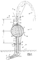
- FIG 1 there is shown a device 1 according to the invention which is installed in a fountain which only the water level 2 of its basin is shown.
- the device 1 comprises means 3A for transmitting light rays and an associated focusing lens 3B.
- This lens 3B is formed by an envelope 4 of spherical shape which is made of an optically transparent material such as a plastic or glass and which defines an internal cavity 5 filled with water during operation of the fountain.
- the spherical envelope 4 comprises at its base a water inlet opening 6 and at its top a water outlet opening 8. These openings are therefore made in the casing 4 at diametrically opposite locations. .
- the section of the inlet opening 6 is slightly greater than that of the outlet opening 8.
- the cavity 5 of the casing 4 is connected to a not shown water supply via a water inlet tube 10 sealingly fixed in the opening 6.
- a nozzle 11 for forming an upward water jet 12 is formed by a tube 13 which is sealed and normal to the outer surface of the envelope in the outlet opening 8. This nozzle 11 is therefore connected at supplying water through the internal cavity 5 and the water inlet tube 10.
- the tubes 10 and 13 are also made of an optically transparent material.
- the light ray emission means 3A comprise a light source 14 and an optical fiber bundle 16.
- the input ends 18 of the optical fibers 16 are connected to the light source 14 while the ends 20 are that is, the exit ends of the light rays are fixed by means of a ring 21 around the water inlet tube 10 so that they form an annular assembly for emitting light rays in the direction of the light. spherical envelope 4.
- the water arriving from the water supply means progressively fills, from the water inlet tube 10, the internal cavity 5 of the spherical envelope 4 to be ejected through the water.
- the jet of water 12 has a parabolic shape with an upward portion 26, a crown portion 27 and a downward portion 28 .
- the envelope 4 filled with water constitutes a focusing lens.
- This focusing lens has two focal points F and F 'located respectively upstream and downstream of the lens at a focal distance f.
- the optical axis of the lens is defined by a straight line passing through these two foci F and F '.
- the light rays emanating from the ends 20 of the optical fibers 16 are therefore directed by the lens towards the jet 12 and illuminate it substantially in its direction of projection indicated by the arrow 29.
- f not water ( not water - 1 ) R two where R is the radius of the spherical envelope 4.
- R is the radius of the spherical envelope 4.
- the spherical shape of the focusing lens formed by the envelope 4 filled with water is advantageous because such a lens has a large numerical aperture approaching 0.5. Due to this large numerical aperture, the focusing lens is able to collect a maximum of the light energy emitted by the ends 20 of the optical fibers 16 and thus makes it possible to optimize the ratio between the light energy produced by the source 14 and the one actually serving to make the jet of water 12 bright.
- Another important point of the optical assembly of the device according to the invention concerns the positioning of the ends 20 of the optical fibers with respect to the focusing lens formed by the spherical envelope 4 filled with water.
- the ends 20 are positioned at a distance equal to or greater than the focal length f of the focusing lens calculated using the above-mentioned relationship. More particularly, in the case of a very high water jet, it will be chosen to place the ends at the focal length f of the lens (see FIG.
- the light ray 30 After a refraction at the envelope / air interface, the light ray 30 passes through the water contained in the spherical cavity 5, penetrates directly into the water jet 12 and propagates inside it by multiple reflections on the water / air interface of the jet 12. Indeed, the jet of water 12 projected into the air acts as a light conductor because the refractive index of the air is lower than that of the water as mentioned before. During these multiple reflections, a portion of the light energy escapes along the jet which contributes to the latter light.
- the light beam 32 propagates more eccentrically with respect to the center of the casing 4 than the spoke 30. It is refracted at each interface of the casing 4 with the air and directed towards the periphery 33 of the water jet .
- this ray 32 meets the periphery 33 of the jet 12, that is to say the air / water interface of the jet, a first portion 34 of the ray is reflected thereby contributing to the jet of water 12 light at this location .
- This first part 34 also serves, as a function of its path, to illuminate the vertex portion 27 or the downward portion 28 of the water jet 12.
- a second portion 36 of the spoke 32 enters the jet 12.
- this ray 36 is then divided into a first portion 38 reflected towards the inside of the jet and a second portion 40 which escapes from the jet 12 and makes the last light at the place of its exit.
- the second part 38 spreads inside the ascending part of the jet 26 as has been explained about the propagation of the light beam 30.
- the jet of water is made bright on the one hand by the external reflections on the periphery of the water jet, and on the other hand by the light rays that propagate inside the jet. Since the light rays emerge from the optical fiber in the form of a beam of rays whose divergence is typically 60 °, it is possible to illuminate the jet of water 12 homogeneously over most of its parabolic trajectory. the crown portion 27 and the decending portion 28 of the jet being substantially illuminated by the portions of the light rays reflected at the water / air or air / water interface of that portion.
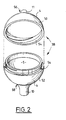
- the spherical envelope 4 may opacify rather quickly due to a deposit on the inner wall of the envelope 4.
- the applicants propose the development of the spherical envelope 4 shown in Figure 2.
- the spherical envelope 4 is made by two semi-spherical caps 50 and 52 provided with complementary assembly means 54.
- These means 54 are, for example, screw assembly means that make it possible to lock a cap against each other to prevent accidental separation of the ice caps when the pressure of the water in the cavity is high.
- the semi-spherical caps 50 and 52 are made of optically transparent plastic.
- the top cap 50 has at its top 56 a nozzle 12 integrally.
- the lower cap 52 comprises at its base 58 a water inlet tube 10 integrally.
- the water supply tube 10 is connected, for example, to an existing nozzle of the fountain and is held in position by means of a support, not shown. At this stage, it is already possible to carry out a first test to orient and control the jet of water sprayed from the nozzle 11. Finally, the ends of the optical fibers to be fixed are fixed by means of the fixing ring 21. the appropriate distance, as described above, so as to form an annular assembly of light ray emission.
- This arrangement has the advantage that the water inlet tube 10 is automatically centered with respect to the optical axis of the focusing lens and serves as a support not only at the output end 20 of the optical fibers, but also to the 3B lens itself. It is understood that the device according to the invention is easy to install and can be adapted to a multitude of existing fountains.
- FIG 3 shows another embodiment of the device 1 of the invention.
- the elements identical to those of Figures 1 and 2 bear the same reference numbers.
- This device comprises, as focusing lens, a ball 60 made of an optically transparent material whose refractive index is greater than that of air, in particular greater than that of water, such as, for example, glass or a plastics material. .
- a ball 60 made of an optically transparent material whose refractive index is greater than that of air, in particular greater than that of water, such as, for example, glass or a plastics material.
- this ball 60 is formed a cylindrical central duct 62 with circular section.
- the ball 60 is threaded onto a tube 64 of water supply means which is connected to a not shown water supply.
- this tube 64 is rigid and made of an optically transparent material. Its upper end constitutes a jet formation nozzle 11 12.
- the ball 60 is held in position on the one hand by the tube 64 on which it is threaded, and on the other hand by a collar 66 mounted on the conduit 64.
- the ball 60 rests on the collar 66 and is thus assured against a vertical displacement.
- the nozzle 12 only slightly exceeds the top of the ball 60.
- the optical fibers 16 are fixed around the duct 64 as has been explained with reference to FIG. 1. Of course, when positioning the ends 20 of the optical fibers 16 , it must be taken into account that the focal length of the ball is calculated in this case with the refractive index of the material in which the ball is made.
- this device is equivalent to that of the device shown in Figure 1 except that light rays 68 which are equivalent to the rays 30 of Figure 1 undergo a total reflection at the interface between the tube 64 and the water lying in it.
- the reflected portion 70 will serve primarily to illuminate the top 27 and the downward portion 28 of the jet.
- This embodiment has the advantage that the focusing lens formed by the ball 60 does not opacify from the inside during operation of the fountain. In addition, such a ball of glass or plastic can be easily cleaned. In addition, this embodiment also adapts easily to existing fountains.
- conduit 62 it is intended to connect the conduit 62 directly to the tube 64.
- the conduit 62 serves with its water jet nozzle outlet end.
- these assembled segments exert a lens effect on the light rays at the output of the optical fibers comparable to that of the ball 60 of FIG. 3, the operation of the device according to the invention is not modified.
- the focusing lens was disposed in the air. But it is also possible to partially dispose of it in water. In this case, the focal length of the lens is varied according to the level of water according to well-known optical laws. Such an arrangement may be interesting in the case where it is also necessary to illuminate the basin of the fountain from which is projected the jet of water 12. Indeed, in the case of a partially immersed lens, a portion of the light rays is reflected at the envelope / water or ball / water interface, so that the bottom of the pool is also lit.
- the device according to Figure 3 it is also provided to fully immerse the ball so that only the nozzle 12 protrudes from the water surface. Because the index of glass or plastic is greater than that of water, ball 60 still acts as an optical lens.
- the focal length of this optical element is now calculated taking into account the ratio of the refractive indices between the material of the ball and the water instead of that between the material of the ball and the air. In this case, the light beam concentration power of the ball 60 decreases which consequently increases the focal length.
- Advantageous development of the device consists, for example, in providing the spherical envelope 4 shown in FIG. 1 with several nozzles, such as simple outlet openings, in order to produce a set of luminous water jets.
- FIG 4 is shown a shower installation which comprises a device according to the invention.
- the elements identical to those of Figures 1 to 3 bear the same reference numbers.
- the focusing lens of the device is formed by a convex plane-shaped envelope 80 made of an optically transparent material and forming a shower head.
- the envelope 80 has a plurality of water jet outlet apertures 84.
- the envelope 80 is fed by a water inlet tube 86 which is fixed in an opening intake 87 formed centrally in the flat portion 88 of the casing 80.
- the sum of the sections of the outlet openings 84 is smaller than the section of the inlet opening 87.
- the optical fibers are fixed by means of the ring 21 a little beyond the focal length of the plano-convex lens formed by the envelope 80 filled with water around the tube 86.
- the operation of this device is equivalent to that of the device of FIG.
- This device according to the invention is distinguished by the simplicity of installation. Indeed, it is possible to install it on the majority of the existing fountains with minor modifications of the fountains nozzles. Either one uses the device represented in FIG. 1 in which one fixes the envelope on an existing nozzle, or one equips the exit of the nozzle of the fountain of a tube adapted to be able to thread the ball 60.
- FIGS. 1, 3 and 4. Another interesting variant is the adaptation of the device to a cascade.
- flat jets is provided instead of a spherical lens cylindrical lens provided with a passage of rectangular section through which the water passes and which forms a flat water jet.
- This cylindrical lens can be made in the same way as the lenses of FIGS. 1, 3 and 4.
- the optical fibers are arranged in rows arranged on each side of the flat jet and illuminate it in the same way as this has been explained with reference to Figures 1, 3 and 4.
Landscapes
- Engineering & Computer Science (AREA)
- Health & Medical Sciences (AREA)
- Public Health (AREA)
- General Engineering & Computer Science (AREA)
- Epidemiology (AREA)
- Life Sciences & Earth Sciences (AREA)
- Hydrology & Water Resources (AREA)
- Water Supply & Treatment (AREA)
- Special Spraying Apparatus (AREA)
Claims (20)
- Vorrichtung (1) zum Beleuchten mindestens eines Wasserstrahls (12), der ausgehend von Mitteln (11) zur Bildung eines Strahls in eine Richtung gespritzt wird, welche mit einer Wasserversorgung durch Wasserzuführungsmittel (10, 5, 64) verbunden sind, wobei diese Vorrichtung umfasst:- Mittel (3A) zum Emittieren von Lichtstrahlen, und- optische Mittel (3B) zur Orientierung der Lichtstrahlen, die von den Emissionsmitteln (3A) ausgehen, auf den Wasserstrahl (12, 85), wobei die optischen Mittel dazu eine Fokussierungslinse (4, 60) enthalten, die zwei Brennpunkte besitzt, wobei die Emissionsmittel (3A) und die zugehörigen optischen Mittel (3B) den Wasserstrahl (12, 85) im Wesentlichen in der Spritzrichtung von diesen erleuchten,dadurch gekennzeichnet, dass die Fokussierungslinse (4, 60) einen Hohlraum (5, 62) umfasst, durch den sich die Wasserzuführungsmittel (5, 64) erstrecken.
- Vorrichtung nach Anspruch 1, dadurch gekennzeichnet, dass einer der Brennpunkte vor der Linse liegt, während der andere Brennpunkt hinter der Linse (4, 60) liegt.
- Vorrichtung nach Anspruch 1 oder 2, dadurch gekennzeichnet, dass die Mittel zur Emission der Lichtstrahlen eine Lichtquelle (14) und Lichtleiter (16) umfassen, die durch erste Enden (18) mit der Lichtquelle (14) verbunden sind und deren andere Enden (20) eine Austrittseinrichtung für die Lichtstrahlen bilden.
- Vorrichtung nach Anspruch 3, dadurch gekennzeichnet, dass die Lichtleiter (16) durch ein Bündel von optischen Fasern gebildet sind.
- Vorrichtung nach Anspruch 3 oder 4 für Wasserzuführungsmittel mit einem starren Rohr (10, 64), das in einer vordefinierten Orientierung gehalten wird, dadurch gekennzeichnet, dass die optischen Orientierungsmittel hinter diesem Rohr angeordnet sind; dass die optische Achse der optischen Orientierungsmittel bezüglich des Rohrs zentriert ist und dass die optischen Orientierungsmittel und die Austrittseinrichtung (20) für die Lichtstrahlen durch dieses Rohr abgestützt sind.
- Vorrichtung nach Anspruch 5, dadurch gekennzeichnet, dass die Austrittsenden der Lichtleiter (16), die die Austrittseinrichtung (20) für die Lichtstrahlen bilden, um das starre Rohr der Wasserzuführungsmittel (10, 86) befestigt sind, um eine ringförmige Baueinheit zur Emission von Lichtstrahlen zu bilden.
- Vorrichtung nach einem der Ansprüche 1 bis 6, dadurch gekennzeichnet, dass der Hohlraum (5) in die Wasserzuführungsmittel integriert ist.
- Vorrichtung nach einem der vorangehenden Ansprüche, dadurch gekennzeichnet, dass die Fokussierungslinse (4, 60) die Form einer Kugel besitzt.
- Vorrichtung nach einem der Ansprüche 1 oder 7 für einen ebenen Wasserstrahl, dadurch gekennzeichnet, dass die Fokussierungslinse eine Zylinderlinse ist.
- Vorrichtung nach einem der vorangehenden Ansprüche, dadurch gekennzeichnet, dass die Fokussierungslinse eine Umhüllung (4) umfasst, die aus einem optisch durchlässigen Material hergestellt ist und den Hohlraum (5) festlegt, der im Betrieb durch die Wasserzuführungsmittel (10) mit Wasser gefüllt wird.
- Vorrichtung nach Anspruch 10, dadurch gekennzeichnet, dass die Umhüllung (4) einerseits mit einer Einlassöffnung (6), die mit den Wasserzuführungsmitteln (10) verbunden ist, und andererseits mit mindestens einer Ausgangsöffnung (8), die einen Teil der Mittel (11) zur Bildung des mindestens einen Wasserstrahls bildet, versehen ist.
- Vorrichtung nach einem der Ansprüche 10 oder 11, dadurch gekennzeichnet, dass jede Ausgangsöffnung eine Düse zur Bildung eines Wasserstrahls bildet.
- Vorrichtung nach Anspruch 12, dadurch gekennzeichnet, dass die oder jede Düse (11) ein Rohr (13) umfasst, das normalerweise beinahe an der Oberfläche der Umhüllung (4) befestigt ist.
- Vorrichtung nach Anspruch 8 gemeinsam mit einem der Ansprüche 10 bis 13 genommen, dadurch gekennzeichnet, dass die kugelförmige Umhüllung (4) zwei halbkugelförmige Kappen (50, 52) und komplementäre Mittel (54) zur Montage der zwei Kappen (50; 52) umfasst, die dem Wasserdruck im Hohlraum (5) standhalten.
- Vorrichtung nach einem der Ansprüche 1 bis 9, dadurch gekennzeichnet, dass die Fokussierungslinse aus einem massiven Körper (60) aus einem optisch durchlässigen Material gebildet ist, in dem der Hohlraum (62) ausgebildet ist, wobei der Brechungsindex des massiven Körpers größer als jener von Luft, vorzugsweise größer als jener von Wasser ist.
- Vorrichtung nach Anspruch 15, dadurch gekennzeichnet, dass der Hohlraum (62) in Form eines zentralen zylindrischen Durchgangs mit kreisförmigem Querschnitt hergestellt ist.
- Vorrichtung nach Anspruch 16, dadurch gekennzeichnet, dass ein Ende des zylindrischen zentralen Durchgangs mit Wasserzuführungsmitteln verbunden ist und dass das andere Ende eine Düse bildet oder dazu ausgelegt ist, mit einer Düse verbunden zu werden.
- Vorrichtung nach einem der Ansprüche 3 bis 17, dadurch gekennzeichnet, dass die Austrittseinrichtung (20) der Emissionsmittel (14, 18) der Lichtstrahlen in einem Abstand, der größer als oder gleich der Brennweite f der optischen Orientierungsmittel ist, vor diesen angeordnet ist.
- Brunnen mit Mitteln zur Bildung mindestens eines Strahls, einer Wasserversorgung und Wasserzuführungsmitteln, die die Versorgung mit den Mitteln zur Bildung des mindestens einen Wasserstrahls verbinden, dadurch gekennzeichnet, dass er mindestens eine Vorrichtung nach einem der Ansprüche 1 bis 18 umfasst.
- Wasserfall mit Mitteln zur Bildung eines ebenen Wasserstrahls, die mit einer Wasserversorgung verbunden sind, dadurch gekennzeichnet, dass er mindestens eine Vorrichtung nach Anspruch 9 zusammengenommen mit einem der Ansprüche 1 bis 5, 10 bis 13 oder 15 bis 18 umfasst.
Applications Claiming Priority (2)
| Application Number | Priority Date | Filing Date | Title |
|---|---|---|---|
| FR9701620A FR2759443B1 (fr) | 1997-02-12 | 1997-02-12 | Dispositif pour rendre au moins un jet d'eau lumineux |
| FR9701620 | 1997-02-12 |
Publications (2)
| Publication Number | Publication Date |
|---|---|
| EP0862016A1 EP0862016A1 (de) | 1998-09-02 |
| EP0862016B1 true EP0862016B1 (de) | 2006-08-30 |
Family
ID=9503617
Family Applications (1)
| Application Number | Title | Priority Date | Filing Date |
|---|---|---|---|
| EP98400212A Expired - Lifetime EP0862016B1 (de) | 1997-02-12 | 1998-02-02 | Vorrichtung zur Beleuchtung von mindestens einem Wasserstrahls |
Country Status (4)
| Country | Link |
|---|---|
| US (1) | US6076741A (de) |
| EP (1) | EP0862016B1 (de) |
| DE (1) | DE69835711D1 (de) |
| FR (1) | FR2759443B1 (de) |
Families Citing this family (37)
| Publication number | Priority date | Publication date | Assignee | Title |
|---|---|---|---|---|
| US6375342B1 (en) * | 2000-03-17 | 2002-04-23 | Oasis Waterfalls Llc | Illuminated waterfall |
| US6484952B2 (en) * | 2000-12-20 | 2002-11-26 | Super Vision International, Inc. | Fiber optic illuminated waterfall |
| US6681508B2 (en) | 2001-03-14 | 2004-01-27 | Massachusetts Institute Of Technology | Visual display device |
| US6543925B2 (en) * | 2001-03-21 | 2003-04-08 | Robert L. Kuykendal | Multi-colored fountain light |
| US6443364B1 (en) * | 2001-11-01 | 2002-09-03 | Lin Chung-Kuei | Candle stand in combination with a fountain |
| WO2003041874A1 (en) * | 2001-11-14 | 2003-05-22 | Aqua Conservation Systems, Inc. | Irrigation control system |
| US6644561B1 (en) * | 2002-03-12 | 2003-11-11 | Patrick David Daane | Color beam sprinkler lights |
| US20050047143A1 (en) * | 2003-09-02 | 2005-03-03 | Currie Joseph Edward | Single light illumination system for a fluid tap |
| US20050148881A1 (en) * | 2003-12-19 | 2005-07-07 | Fomitchov Ravel A. | High-frequency intensity-modulated incoherent optical source for biomedical optical imaging |
| US7162752B2 (en) * | 2004-01-16 | 2007-01-16 | Watkins Manufacturing Corporation | Laminar flow lighted waterfall apparatus for spa |
| EP1819410B1 (de) * | 2004-10-26 | 2019-03-13 | Pentair Water Pool and Spa, Inc. | Inline-chloriervorrichtung mit integralem steuerpaket und wärmeableitung |
| US7845579B2 (en) * | 2004-11-17 | 2010-12-07 | Bruce Johnson | Laminar flow water jet with energetic pulse wave segmentation and controller |
| US20060163374A1 (en) * | 2005-01-25 | 2006-07-27 | Russ Wooten | Fountain waterjet |
| US7384165B2 (en) * | 2005-07-05 | 2008-06-10 | Kevin Doyle | Water feature with an LED system |
| US8763925B2 (en) * | 2005-11-17 | 2014-07-01 | Pentair Water Pool And Spa, Inc. | Laminar flow water jet with wave segmentation, additive, and controller |
| US20070236913A1 (en) * | 2006-04-06 | 2007-10-11 | Rain Bird Europe, S.A.R.L. | Lighting Process And Mechanism |
| USD558914S1 (en) | 2006-06-06 | 2008-01-01 | S.C. Johnson & Son, Inc. | Light object |
| US7410269B2 (en) | 2006-06-06 | 2008-08-12 | S.C. Johnson & Son, Inc. | Decorative light system |
| USD558913S1 (en) | 2006-06-15 | 2008-01-01 | S.C. Johnson & Son, Inc. | Combination light object and base |
| US7458698B2 (en) | 2006-06-15 | 2008-12-02 | S.C. Johnson & Son, Inc. | Decorative light system |
| USD581092S1 (en) | 2006-06-15 | 2008-11-18 | S.C. Johnson & Son, Inc. | Base for a light object |
| US8578884B2 (en) * | 2006-07-20 | 2013-11-12 | John M Hawk | Illuminated drinking system |
| RU2336459C1 (ru) * | 2007-03-15 | 2008-10-20 | Закрытое акционерное общество "Светлана-Оптоэлектроника" | Устройство для освещения потока жидкости |
| WO2009059490A1 (en) * | 2007-11-05 | 2009-05-14 | Yulam Wong | Led lamp illuminant insert |
| WO2009104987A1 (ru) * | 2008-02-18 | 2009-08-27 | Shtrom Dmitry Yurevich | Устройство для освещения |
| US9416034B2 (en) | 2009-01-28 | 2016-08-16 | Pentair Water Pool And Spa, Inc. | pH balancing system |
| US10006214B2 (en) | 2009-01-28 | 2018-06-26 | Pentair Water Pool And Spa, Inc. | pH balancing dispenser and system with piercing opener |
| FR2958007B1 (fr) | 2010-03-23 | 2018-06-22 | Francois Dandrel | Dispositif pour rendre lumineux au moins un jet d'eau et installations comportant un tel dispositif |
| US8622247B2 (en) * | 2011-07-13 | 2014-01-07 | Steve Zuloff | Light up liquid projection device and method thereof |
| US10315214B2 (en) * | 2012-10-30 | 2019-06-11 | Custom Molded Products, Llc | Lighted waterfall device with spreading manifold |
| US9914146B2 (en) * | 2012-10-30 | 2018-03-13 | Custom Molded Products, Llc | Lighted waterfall device |
| USD755449S1 (en) * | 2014-06-18 | 2016-05-03 | Radio Systems Corporation | Orb pet water fountain |
| USD819898S1 (en) | 2016-10-25 | 2018-06-05 | Radio Systems Corporation | Orb pet water fountain |
| US10393363B2 (en) | 2017-04-25 | 2019-08-27 | Delta Faucet Company | Illumination device for a fluid delivery apparatus |
| US11118368B2 (en) | 2018-06-22 | 2021-09-14 | Hayward Industries, Inc. | Laminar water feature |
| WO2020018529A1 (en) * | 2018-07-18 | 2020-01-23 | Sturdy Corporation | Nozzle assembly with articulating nozzles |
| US11602032B2 (en) | 2019-12-20 | 2023-03-07 | Kohler Co. | Systems and methods for lighted showering |
Family Cites Families (10)
| Publication number | Priority date | Publication date | Assignee | Title |
|---|---|---|---|---|
| FR638540A (fr) * | 1926-12-08 | 1928-05-26 | Fontaine lumineuse | |
| FR1187689A (fr) * | 1957-04-30 | 1959-09-15 | Cie D Electricite | Nouveau dispositif d'illumination de jets d'eau |
| FR1567059A (de) * | 1967-09-27 | 1969-05-16 | ||
| GB2099125B (en) * | 1981-05-22 | 1984-06-13 | Filtapac The Co Ltd | Illuminated water fountain |
| FR2562637B1 (fr) * | 1984-04-06 | 1986-07-11 | Dandrel Francois | Procede et dispositif pour rendre les jets d'eau lumineux et application de ce dispositif |
| US4749126A (en) * | 1984-05-09 | 1988-06-07 | Kessener H P M | Liquid outlet adapted to provide lighting effects and/or for illumination |
| US5078320A (en) * | 1988-02-26 | 1992-01-07 | Wet Design | Water displays |
| US4936506A (en) * | 1988-11-14 | 1990-06-26 | Ryan James E | Swimming pool fountain |
| US5160086A (en) * | 1990-09-04 | 1992-11-03 | Kuykendal Robert L | Lighted laminar flow nozzle |
| GB2288974B (en) * | 1994-04-27 | 1998-09-30 | Lin Li | Sanitary installations with illuminated water |
-
1997
- 1997-02-12 FR FR9701620A patent/FR2759443B1/fr not_active Expired - Fee Related
-
1998
- 1998-02-02 DE DE69835711T patent/DE69835711D1/de not_active Expired - Lifetime
- 1998-02-02 EP EP98400212A patent/EP0862016B1/de not_active Expired - Lifetime
- 1998-02-06 US US09/019,988 patent/US6076741A/en not_active Expired - Fee Related
Also Published As
| Publication number | Publication date |
|---|---|
| DE69835711D1 (de) | 2006-10-12 |
| FR2759443A1 (fr) | 1998-08-14 |
| EP0862016A1 (de) | 1998-09-02 |
| US6076741A (en) | 2000-06-20 |
| FR2759443B1 (fr) | 1999-04-09 |
Similar Documents
| Publication | Publication Date | Title |
|---|---|---|
| EP0862016B1 (de) | Vorrichtung zur Beleuchtung von mindestens einem Wasserstrahls | |
| EP1338844B1 (de) | Kfz-signalleuchte mit einem optischen teil, das selbst eine signal-funktion erfüllt | |
| EP1443265B1 (de) | Lichtleiter mit Reflektoren | |
| EP1288562B1 (de) | Beleuchtungs- oder Signalvorrichtung für Fahrzeug | |
| FR2995977B1 (fr) | Guide de lumiere pour un dispositif d'eclairage et/ou de signalisation de vehicule automobile | |
| EP2230446B1 (de) | Beleuchtungs- oder Signalisierungsvorrichtung für ein Kraftfahrzeug | |
| EP1416220A1 (de) | Signalleuchte mit einem optichen System zur Sammlung und Verteilung des Lichtbündels nach einem ringförmigen Reflektor | |
| EP1881265B1 (de) | Beleuchtungseinrichtung mit einer Lichtleiterplatte, die eine kreisbogenförmige, rückstrahlende Reflexionsfläche aufweist | |
| EP1857732A1 (de) | Vorrichtung zur Beleuchtung und/oder Signalisierung für Kraftfahrzeuge | |
| FR2992711A1 (fr) | Dispositif optique de vehicule automobile a elements dioptriques integres au conduit de lumiere | |
| FR2472135A1 (fr) | Projecteur, notamment pour vehicules automobiles | |
| FR2564982A1 (fr) | Embout de couplage d'un guide de lumiere a une source lumineuse, notamment pour un eclairage de ville integre a un ensemble projecteur pour automobile | |
| FR2904093A1 (fr) | Dispositif d'eclairage ou de signalisation comportant une nappe de guidage galbee | |
| FR2562637A1 (fr) | Procede et dispositif pour rendre les jets d'eau lumineux et application de ce dispositif | |
| EP1367318B1 (de) | Signalleuchte mit einem optischen Element zur selbständigen Ausführung einer Signalfunktion | |
| EP0633424B1 (de) | Faseroptische Lichtquelleneinrichtung mit verstellbarem Lichtbündel | |
| EP1739468B1 (de) | Beleuchtungs- oder Signalvorrichtung für Kraftfahrzeuge | |
| FR2851028A1 (fr) | Dispositif d'eclairage | |
| FR2628823A1 (fr) | Projecteur de lumiere | |
| EP1850065B1 (de) | Vorrichtung zur Lichtverteilung in Lichtleitern | |
| FR2805885A1 (fr) | Dispositif d'eclairage et de signalisation pour vehicule a conduit de lumiere commandable | |
| EP1596126A1 (de) | Signal- bzw Beleuchtungseinrichtung mit einem optischen Teil zur selbstständigen Erzeugung eines vorschriftsmässigen Lichtbündels | |
| EP4652405A1 (de) | Leuchtmodul einer beleuchtungs- und/oder signalvorrichtung für ein fahrzeug | |
| FR2829562A3 (fr) | Lampe pour vehicules automobiles | |
| EP3144588A1 (de) | Leuchtvorrichtung, insbesondere für kraftfahrzeug |
Legal Events
| Date | Code | Title | Description |
|---|---|---|---|
| PUAI | Public reference made under article 153(3) epc to a published international application that has entered the european phase |
Free format text: ORIGINAL CODE: 0009012 |
|
| AK | Designated contracting states |
Kind code of ref document: A1 Designated state(s): BE DE ES GB IT NL |
|
| AX | Request for extension of the european patent |
Free format text: AL;LT;LV;MK;RO;SI |
|
| 17P | Request for examination filed |
Effective date: 19990121 |
|
| AKX | Designation fees paid |
Free format text: BE DE ES GB IT NL |
|
| RBV | Designated contracting states (corrected) |
Designated state(s): BE DE ES GB IT NL |
|
| 17Q | First examination report despatched |
Effective date: 20031202 |
|
| GRAP | Despatch of communication of intention to grant a patent |
Free format text: ORIGINAL CODE: EPIDOSNIGR1 |
|
| RIC1 | Information provided on ipc code assigned before grant |
Ipc: F21S 8/00 20060101AFI20060309BHEP |
|
| GRAS | Grant fee paid |
Free format text: ORIGINAL CODE: EPIDOSNIGR3 |
|
| GRAA | (expected) grant |
Free format text: ORIGINAL CODE: 0009210 |
|
| AK | Designated contracting states |
Kind code of ref document: B1 Designated state(s): BE DE ES GB IT NL |
|
| PG25 | Lapsed in a contracting state [announced via postgrant information from national office to epo] |
Ref country code: NL Free format text: LAPSE BECAUSE OF FAILURE TO SUBMIT A TRANSLATION OF THE DESCRIPTION OR TO PAY THE FEE WITHIN THE PRESCRIBED TIME-LIMIT Effective date: 20060830 Ref country code: IT Free format text: LAPSE BECAUSE OF FAILURE TO SUBMIT A TRANSLATION OF THE DESCRIPTION OR TO PAY THE FEE WITHIN THE PRESCRIBED TIME-LIMIT;WARNING: LAPSES OF ITALIAN PATENTS WITH EFFECTIVE DATE BEFORE 2007 MAY HAVE OCCURRED AT ANY TIME BEFORE 2007. THE CORRECT EFFECTIVE DATE MAY BE DIFFERENT FROM THE ONE RECORDED. Effective date: 20060830 Ref country code: GB Free format text: LAPSE BECAUSE OF FAILURE TO SUBMIT A TRANSLATION OF THE DESCRIPTION OR TO PAY THE FEE WITHIN THE PRESCRIBED TIME-LIMIT Effective date: 20060830 |
|
| REG | Reference to a national code |
Ref country code: GB Ref legal event code: FG4D Free format text: NOT ENGLISH |
|
| REF | Corresponds to: |
Ref document number: 69835711 Country of ref document: DE Date of ref document: 20061012 Kind code of ref document: P |
|
| PG25 | Lapsed in a contracting state [announced via postgrant information from national office to epo] |
Ref country code: DE Free format text: LAPSE BECAUSE OF FAILURE TO SUBMIT A TRANSLATION OF THE DESCRIPTION OR TO PAY THE FEE WITHIN THE PRESCRIBED TIME-LIMIT Effective date: 20061201 |
|
| PG25 | Lapsed in a contracting state [announced via postgrant information from national office to epo] |
Ref country code: ES Free format text: LAPSE BECAUSE OF FAILURE TO SUBMIT A TRANSLATION OF THE DESCRIPTION OR TO PAY THE FEE WITHIN THE PRESCRIBED TIME-LIMIT Effective date: 20061211 |
|
| NLV1 | Nl: lapsed or annulled due to failure to fulfill the requirements of art. 29p and 29m of the patents act | ||
| GBV | Gb: ep patent (uk) treated as always having been void in accordance with gb section 77(7)/1977 [no translation filed] |
Effective date: 20060830 |
|
| PLBE | No opposition filed within time limit |
Free format text: ORIGINAL CODE: 0009261 |
|
| STAA | Information on the status of an ep patent application or granted ep patent |
Free format text: STATUS: NO OPPOSITION FILED WITHIN TIME LIMIT |
|
| 26N | No opposition filed |
Effective date: 20070531 |
|
| PGFP | Annual fee paid to national office [announced via postgrant information from national office to epo] |
Ref country code: BE Payment date: 20090311 Year of fee payment: 12 |
|
| BERE | Be: lapsed |
Owner name: DANDREL, NEE DUVEAU, GENEVIEVE MARIE Effective date: 20100228 Owner name: DANDREL, FRANCOIS PAUL Effective date: 20100228 |
|
| PG25 | Lapsed in a contracting state [announced via postgrant information from national office to epo] |
Ref country code: BE Free format text: LAPSE BECAUSE OF NON-PAYMENT OF DUE FEES Effective date: 20100228 |