EP0862018A1 - Dispositif de montage de brûleurs à l' intérieur d' un conduit de gaz - Google Patents
Dispositif de montage de brûleurs à l' intérieur d' un conduit de gaz Download PDFInfo
- Publication number
- EP0862018A1 EP0862018A1 EP98430005A EP98430005A EP0862018A1 EP 0862018 A1 EP0862018 A1 EP 0862018A1 EP 98430005 A EP98430005 A EP 98430005A EP 98430005 A EP98430005 A EP 98430005A EP 0862018 A1 EP0862018 A1 EP 0862018A1
- Authority
- EP
- European Patent Office
- Prior art keywords
- burner
- duct
- head
- outside
- axis
- Prior art date
- Legal status (The legal status is an assumption and is not a legal conclusion. Google has not performed a legal analysis and makes no representation as to the accuracy of the status listed.)
- Granted
Links
Images

Classifications
-
- F—MECHANICAL ENGINEERING; LIGHTING; HEATING; WEAPONS; BLASTING
- F24—HEATING; RANGES; VENTILATING
- F24H—FLUID HEATERS, e.g. WATER OR AIR HEATERS, HAVING HEAT-GENERATING MEANS, e.g. HEAT PUMPS, IN GENERAL
- F24H3/00—Air heaters
-
- F—MECHANICAL ENGINEERING; LIGHTING; HEATING; WEAPONS; BLASTING
- F23—COMBUSTION APPARATUS; COMBUSTION PROCESSES
- F23C—METHODS OR APPARATUS FOR COMBUSTION USING FLUID FUEL OR SOLID FUEL SUSPENDED IN A CARRIER GAS OR AIR
- F23C5/00—Disposition of burners with respect to the combustion chamber or to one another; Mounting of burners in combustion apparatus
- F23C5/02—Structural details of mounting
- F23C5/06—Provision for adjustment of burner position during operation
-
- F—MECHANICAL ENGINEERING; LIGHTING; HEATING; WEAPONS; BLASTING
- F23—COMBUSTION APPARATUS; COMBUSTION PROCESSES
- F23C—METHODS OR APPARATUS FOR COMBUSTION USING FLUID FUEL OR SOLID FUEL SUSPENDED IN A CARRIER GAS OR AIR
- F23C5/00—Disposition of burners with respect to the combustion chamber or to one another; Mounting of burners in combustion apparatus
- F23C5/02—Structural details of mounting
-
- F—MECHANICAL ENGINEERING; LIGHTING; HEATING; WEAPONS; BLASTING
- F23—COMBUSTION APPARATUS; COMBUSTION PROCESSES
- F23D—BURNERS
- F23D14/00—Burners for combustion of a gas, e.g. of a gas stored under pressure as a liquid
- F23D14/20—Non-premix gas burners, i.e. in which gaseous fuel is mixed with combustion air on arrival at the combustion zone
- F23D14/22—Non-premix gas burners, i.e. in which gaseous fuel is mixed with combustion air on arrival at the combustion zone with separate air and gas feed ducts, e.g. with ducts running parallel or crossing each other
- F23D14/24—Non-premix gas burners, i.e. in which gaseous fuel is mixed with combustion air on arrival at the combustion zone with separate air and gas feed ducts, e.g. with ducts running parallel or crossing each other at least one of the fluids being submitted to a swirling motion
-
- F—MECHANICAL ENGINEERING; LIGHTING; HEATING; WEAPONS; BLASTING
- F23—COMBUSTION APPARATUS; COMBUSTION PROCESSES
- F23D—BURNERS
- F23D17/00—Burners for combustion simultaneously or alternately of gaseous or liquid or pulverulent fuel
- F23D17/002—Burners for combustion simultaneously or alternately of gaseous or liquid or pulverulent fuel gaseous or liquid fuel
Definitions
- the subject of the present invention is a device for mounting burners in a gas pipe in which it circulates and which require burners to operate in atmospheres containing little oxygen.
- the technical sector of the invention is the field of manufacture and assembly of combustion apparatus using liquid and / or gaseous fuels.
- burners in afterburner gas exhaust ducts arranged after the gas turbines and upstream of boilers of recovery of cogeneration units: such burners allow raise the temperature of the turbine gases to 1800 ° C by example and thereby increase the efficiency of said boilers. Moreover, they make it possible to operate said boilers with air fresh oxidizer when the turbines are stopped.
- the sheaths in which the gases to be heated or reheated circulate are several meters wide and high, usually around 6 m, also knowing that the exhaust gases from the turbines are already about 500 ° C or more, to work on such burner heads, you must therefore stop the circulation of hot air and wait for the cooling of the assembly before being able to enter the sheath to access said burners.
- the problem is thus to be able to intervene on heads of burners comprising at least one fuel injection pipe liquid, possibly also with gas injection pipes, placed along the same axis and inside conduits where a gas to be heated or reheated, in order to be able to repair, modify or simply clean said injection nozzles without having to stopping said circulation of gas in said conduit for too long.
- a solution to the problem posed is a device for mounting a such a burner inside a gas pipe and comprising at least a fuel injection nozzle with a nose placed in the head of said burner along an axis parallel to that of said duct; following the invention said injection rod is located inside a sheath supply of air outside the duct to the burner head, is integral, which sheath is arranged transversely to the axis of said conduit; and said cane nose located at the end of a bent part thereof, is movable along said axis of the burner by relative to a guide orifice integral with said burner head which it is capable of being disengaged by displacement, from outside the duct and inside the barrel, the injection rod, which is then completely extractable to and from outside the duct.
- the entire head of the burner and its air supply sleeve are extractable also transversely and out of the duct from outside of this, in particular thanks to at least one hollow post, vertical or inclined and preferably less than 45 ° relative to the vertical; this post is disposed in said duct, suspended from its upper part and supporting horizontal raceways on which are laid support and guide means of said burner head; said vertical or inclined hollow support pole is thus cooled by air circulation inside its own volume by pulling effect natural or by forced ventilation.
- the invention also comprises at least two flaps arranged on the side on the other side of the burner head, tilting around transverse axes audit led and whose shapes, compatible with those inside the duct and the outer ones of the burner head, ensure in position closed the reduction of the gas passage section through at least that of the burner head; preferably said flaps and their axes are also hollow and connected to a vertical or inclined hollow duct, as the vertical or inclined hollow post supporting said heads burners, to also ensure circulation cooling of internal air by natural draft effect or by ventilation.
- Such flaps make it possible to reduce the cross section of the gases to be heated especially when it is fresh combustion air, and not afterburner gases from gas turbines when these are by example stopped.
- burner mounting devices placed inside a gas pipe such as those exhaust from gas turbines: these devices solve the problem installed without having the disadvantages of burners known to date, since on the one hand they make it possible to extract the injection rod (s) from liquid fuel from outside the duct without having to exit the entire burner and therefore practically without stopping the circulation of gas to be heated, and on the other hand to extract the entire the burner head itself quickly enough without having to wait for the sheath cooling; this limits the downtime of installations, especially those of post-combustion cogeneration gas turbines for which production losses are then the more important the longer the stop; following this invention these downtimes are reduced to the absolute minimum by making such easily accessible and removable burners which presents a very important interest in the development of such units in all industries.
- the present invention can be adapted to all types of burners such as those described by way of exemplary embodiment in the figures below; the design of these burners is taken from that described in patent FR2570473 filed in 1984 by the same applicant that the present invention the company EGCI PILLARD and describing parallel flow gas burners with a rosette and a means of hanging flames.
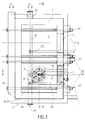
- Figure 1 is a cross-sectional view of a gas circulation in which a burner mounted according to the device of the present invention.
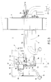
- Figure 2 is an enlarged view of the burner of Figure 1 following the same axis.
- FIG. 3 is a top view in partial section of the burner Figure 2.
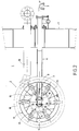
- Figure 4 is a sectional view along IV, IV 'of the gas pipe of figure 1.
- Figure 5 is a sectional view along V, V 'of the same conduit Figure 1 gas.
- Figures 4 and 5 in fact show a section of the gas conduit 1 27 flowing inside thereof and which is of course connected on these inlet and outlet faces to a sheath which can be connected upstream to a gas turbine and downstream to a recovery boiler;
- Figure 1 is a view from the upstream part with a burner head 2 1 in the operating position inside the duct 1 and a second head 2 2 not shown since completely extracted from the duct with the installation of a false door 7 2 or guillotine closing the extraction passage section of said head 2 2 and making it possible to operate the installation without this burner 2 2 .
- a vertical or inclined hollow post 20 is placed in the duct and suspended from its upper part: this vertical post 1 can expand downwards by crossing the lower part of the sheath 1 thanks to a cable gland 20 2 hot gases and thus leaving free the expansion of said post 20 which can be isolated and internally cooled by an outside air circulation 21 1 in natural draft or by ventilation.
- Said vertical post 20 1 supports the horizontal raceways 22 on which are placed support and guide means 23 such as one or more rollers disposed at the bottom of said head 2 of the burner and having a corresponding shape and cooperating with that of the selected raceways 22.
- the latter can bear and be maintained on plates integral with the post 20 while remaining free to expand longitudinally relative to these plates; optionally these raceways, preferably in number 2, can also consist of hollow support tubes, insulated like the support post 20 and cooled by internal air circulation.
- the burners used comprise in a known manner at least a fuel injection nozzle 3, the nose 5 of which is disposed in the head 2 of said burner along an axis XX 'parallel to that of said line 1: according to the invention, said injection pipe 3 is located at the inside of a sheath 6 for supplying air outside the duct 1, the head 2 of the burner with which it is integral; said sheath is arranged along an axis YY 'transverse to that of said conduit 1; and said nose 5 of the rod 3, located at the end of a bent part 4 thereof, is movable along the axis XX 'relative to a guide hole 14 integral with said burner head 2 from which it is capable of being released by displacement of the injection rod 3, from outside the duct 1 and inside the sleeve 6.
- the injection rod is associated for example with a rotating shaft 8 for maneuvering from the outside of the duct 1, located in the sheath 6, parallel to the rod 3 and carrying at least at its distal end a gear 9 2 which comes to cooperate with a rack 10; the latter being located at the end 16 of the sleeve 6 on the side of the head 2 of the burner, the rotation of said gear 9 by the operating shaft 8 causes its movement and that of the injection rod 3 along this rack 10 for engaging and disengaging the nose 5 of the rod 3 relative to the head 2 of the burner.
- the injection pipe is shown in Figure 3 in operating position in solid lines 4, 3a and extractability position in dotted lines 4 b, 3 b.
- Another gear 9 1 or any end piece making it possible to engage an operating key such as a square or a hexagon, is located at the other end of the shaft 8 remaining outside the conduit 1 and makes it possible to ensure the setting in rotation of this shaft 8.
- said rod is integral with a centering guide 11 lateral keeping it at a constant distance along the walls of the sheath 6 which are parallel; this guide 11 or the bent part 4 of the rod 3 can be a support on a stop 30 disposed along said walls in order to maintain the longitudinal position of said rod 3 inside the sheath 6, until the nose 5 injection located at the end of the bent part 4 of the injection rod 3 is guided and properly positioned in the orifice 14 of the injection head which in the case of the examples of the figures is a single central orifice arranged along the axis XX 'of the burner.
- Said burner head 2 also comprises a shutter 16 of the end of the sheath 6 opening laterally along the axis XX 'and downstream of the gas circulation 27 in a shell 16 1 itself closed by a plate stabilizer 13 comprising orifices, such as tangential slots or holes parallel to the axis XX ′ or inclined, for the outlet of external air supplied by said sheath 6, and said orifice 14 for guiding the injection nose 5.
- a external cylinder 12 surrounds at least said ferrule 16 1 and the stabilizing plate 13.
- the surface of the useful gas passage section 27 inside of said cylinder 12 is equal to 20 to 50% of the useful cross-sectional area of the duct 1 in which said burner is located, said percentage being in fact to be considered in proportion to gas in stoichiometric air.
- said burner head 2 comprises blades 15 for rotating the gas, fixed around the ferrule 16 1 for air outlet 16 at the end of the sleeve 6, and injection nozzles 17 for gaseous fuel disposed through and between said blades 15 along axes parallel to that of the duct 1, or convergent or divergent.
- Said inclined blades 15 may be surrounded by a cylindrical hoop 28 delimiting a peripheral ring 31 with the outer cylinder 12.
- This said outer cylinder 12 is an air director which can be possibly convergent and diverge respectively at its upstream orifice 12 1 and its downstream orifice 12 2 .
- Said injection lances 17 of gaseous fuels passing through said inclined fins 15 inject the gas downstream from the plane of the front face of the stabilizing plate 13.
- the assembly constituted by said inclined blades 15, forming a rosette, constitute with said stabilizing plate 13 the flame catcher as described in the previously cited patent FR 2570473.
- Said gas fuel lances 17 may be in number any represented here in number of 6 and come to be connected on at least one gas manifold 18, which can be toroidal in shape revolution as shown in Figure 3 and thus constituted upstream converging openings of said cylinder 12; said collector 18 is connected to the outside by a fuel gas supply tube 19.
- the axis YY 'of the sleeve 6 is arranged perpendicular to the axis XX 'of the burner and the duct 1 but it could be tilted at any other angle transverse, preferably between 45 and 90 ° relative to the axis of said conduit.
- the invention also comprises at least two flaps 24 arranged on either side of the burner head 2, tilting around axes 25 transverse to that of said conduit 1 and whose shapes, compatible with that inside the duct 1 and that outside the head 2 of the burner, ensure in the closed position the reduction of the section of passage of the gas through at least that of the head 1 of the burner.
- said flaps 24 and their axes 25 are hollow and connected to a vertical pipe 26 also hollow; all of these parts internal hollow which can also be connected to the hollow post vertical 20 support for the burner heads 2.
Landscapes
- Engineering & Computer Science (AREA)
- Chemical & Material Sciences (AREA)
- Combustion & Propulsion (AREA)
- Mechanical Engineering (AREA)
- General Engineering & Computer Science (AREA)
- Physics & Mathematics (AREA)
- Thermal Sciences (AREA)
- Gas Burners (AREA)
- Control Of Combustion (AREA)
- Pre-Mixing And Non-Premixing Gas Burner (AREA)
- Combustion Of Fluid Fuel (AREA)
Abstract
Description
- les brûleurs à rampes utilisant uniquement le gaz comme seul combustible et qui sont disposés d'une manière fixe à l'intérieur de ladite gaine de gaz à chauffer ;
- les brûleurs à rampes à gaz et à fuel oil léger comprenant des rampes à gaz fixes comme précédemment et qui viennent s'intercaler entre des têtes de combustion pour le fuel léger, tels que ceux décrits dans la demande de brevet FR 2285574 ; l'ensemble de ces rampes et têtes sont solidaires et ne permettent pas d'utiliser du fuel lourd qui ne peut pas être réparti d'une façon homogène entre les différentes têtes, l'équilibrage sans comptage de débit de fuel oil lourd étant quasiment impossible avec précision du fait du risque de figeage, des écarts de perte de charge en fonction des longueurs des lignes d'alimentation et des différences de hauteur des brûleurs. C'est pour cela que dans les brûleurs à fuel oil lourd il n'est en général utilisé qu'une seule canne d'injection centrale ;
- les brûleurs latéraux ou extérieurs, dont l'axe de la flamme est perpendiculaire ou incliné par rapport au sens d'écoulement des gaz à réchauffer, c'est-à-dire à l'axe d'écoulement principal de la gaine ou du conduit (dont le terme anglais dans ce domaine technique est "duct"). Cette disposition permet de placer le ou les brûleurs à l'extérieur de la gaine à condition de protéger la flamme d'axe sécant, soit en la plaçant dans un logement complètement extérieur à la gaine, le brûleur ne réchauffant pas alors directement les gaz mais jouant le rôle de générateur de gaz chauds, soit en disposant la flamme à l'intérieur de la gaine et en la protégeant par une sorte de déflecteur intérieur pour écarter les gaz à réchauffer de cette flamme transversale, afin d'éviter qu'elle ne soit trop perturbée et ne produise une trop grande quantité d'imbrûlés. Cette disposition présente cependant de multiples inconvénients notamment : il est difficile d'adapter exactement la dimension de la flamme ou des flammes aux dimensions de la gaine ; la chaudière de récupération située en aval du ou des brûleurs ne récupère pas le rayonnement des flammes, d'où une perte de rendement obligeant un surdimensionnement ; les flammes transversales sont toujours plus ou moins perturbées par l'écoulement des gaz à réchauffer qui ont un faible taux d'oxygène ce qui provoque des imbrûlés ; les cotés de la gaine peuvent être détériorés par la proximité des extrémités de flamme ;
- les brûleurs que l'on peut qualifier "d'inducts" puisque disposés entièrement à l'intérieur d'une gaine de circulation de gaz (voir ci-dessus l'origine du mot "duct") ; ce mode d'installation qui est celui utilisé pour les brûleurs de la présente invention, présente l'axe d'écoulement du brûleur parallèle à celui d'écoulement de la gaine ; le nombre des brûleurs ainsi installés est faible, en général toujours égal ou inférieur à 6 et même de préférence 2 ; ils sont alimentés en combustibles liquide ou gazeux par des conduits reliés au coté de la gaine. Ces brûleurs ont d'une part beaucoup plus de possibilité que ceux des deux premiers modes de construction cités ci-dessus puisqu'ils permettent d'utiliser indifféremment tous types de combustibles qu'ils soient liquide, léger, lourd ou gazeux, et d'autre part donnent des résultats de combustion supérieurs à ceux décrits dans le troisième mode décrits ci-dessus du fait de leur positionnement beaucoup plus logique dans l'axe et vers le centre de la gaine ; par contre contrairement aux brûleurs latéraux ou extérieurs, mais comme ceux des deux premiers modes cités, ils sont d'accès très difficile et pour les démonter, les modifier ou les réparer il est nécessaire d'entrer dans la gaine. Ceci n'est pas trop gênant pour des brûleurs à rampes à gaz seul ou même à fuel léger, car les risques d'avoir à opérer des réglages et à effectuer des opérations d'entretien sur de telles rampes sont plus réduits que quand on utilise du fuel oil lourd. Cependant, l'utilisation de gaz spéciaux, tels que des gaz hydrogénés ou entraínant des particules liquides tels que les gaz de raffinerie, nécessite de pouvoir accéder également pour démontage et entretien aux injecteurs de gaz.
Claims (10)
- Dispositif de montage de brûleurs à l'intérieur d'un conduit (1) de gaz et comprenant au moins une canne d'injection (3) de combustible dont le nez (5) est disposé dans la tête (2) dudit brûleur suivant un axe (XX') parallèle à celui dudit conduit (1), caractérisé en ce que ladite canne d'injection (3) est située à l'intérieur d'un fourreau (6) d'alimentation, en air extérieur au conduit (1), de la tête (2) du brûleur dont il est solidaire, et disposé transversalement par rapport à l'axe dudit conduit (1), et ledit nez (5) de la canne (3), situé à l'extrémité d'une partie coudée (4) de celle-ci, est mobile suivant l'axe (XX') par rapport à un orifice (14) de guidage solidaire de ladite tête (2) de brûleur, dont il est apte à être dégagé par déplacement, depuis l'extérieur du conduit (1) et à l'intérieur du fourreau (6), de la canne d'injection (3), qui est alors complètement extractible vers et depuis l'extérieur du conduit (1).
- Dispositif de montage de brûleurs suivant la revendication 1, caractérisé en ce que ladite canne d'injection (3) est associée à un arbre tournant (8) de manoeuvre depuis l'extérieur du conduit (1), parallèle à la canne (3) et portant au moins à son extrémité distale un engrenage (92) qui vient coopérer avec une crémaillère (10) située à l'extrémité (16) du fourreau (6) du coté de la tête (2) du brûleur, la rotation dudit engrenage (9) par l'arbre de manoeuvre (8) entraínant son déplacement et celui de la canne d'injection (3) le long de la crémaillère (10) pour engager et dégager le nez (5) de la canne (3) par rapport à la tête (2) du brûleur.
- Dispositif de montage de brûleurs suivant l'une quelconque des revendications 1 ou 2, caractérisé en ce que l'ensemble de la tête (2) du brûleur et du fourreau (6) d'alimentation en air extérieur sont extractibles transversalement et hors du conduit (1) depuis l'extérieur de celui-ci.
- Dispositif suivant la revendication 3, caractérisé en ce qu'il comporte au moins un poteau (20) vertical creux disposé dans ledit conduit (1), suspendu à sa partie supérieure (201) et supportant des chemins de roulement (22) horizontaux sur lesquels sont posés des moyens (23) d'appui et de guidage de ladite tête (2) du brûleur.
- Dispositif suivant l'une quelconque des revendications 1 à 4, caractérisé en ce qu'il comporte au moins deux volets (24) disposés de part et d'autre de la tête (2) du brûleur, basculant autour d'axes (25) transversaux audit conduit (1) et dont les formes, compatibles avec celle intérieure du conduit (1) et celle extérieure de la tête (2) du brûleur, assurent en position fermée la réduction de la section de passage du gaz à travers au moins celle de la tête (1) du brûleur.
- Dispositif suivant la revendication 5, caractérisé en ce que lesdits volets (24) et leurs axes (25) sont creux et reliés à un conduit vertical (26) également creux.
- Dispositif de montage de brûleurs suivant l'une quelconque des revendications 1 à 6, caractérisé en ce que ladite tête brûleur (2) comprend un obturateur (16) de l'extrémité du fourreau (6) s'ouvrant latéralement suivant l'axe (XX') dans une virole (161) fermée elle-même par une plaque stabilisatrice (13) comportant des orifices de sortie d'air et ledit orifice (14) de guidage du nez d'injection (5), et un cylindre externe (12) entourant au moins ladite virole (161) et la plaque stabilisatrice (13).
- Dispositif suivant la revendication 7, caractérisé en ce que la surface de la section utile de passage de gaz à l'intérieur dudit cylindre externe (12) est égal à 20 à 50 % de la surface de section utile du conduit (1) dans lequel est situé ledit brûleur.
- Dispositif suivant l'une quelconque des revendications 7 à 8, caractérisé en ce que ladite tête de brûleur (2) comprend des pales (15) de mise en rotation du gaz, fixées autour de la virole (161) et de sortie d'air à l'extrémité du fourreau (6), et des lances d'injection (17) de combustible gazeux disposées à travers et entre lesdites pales (15).
- Dispositif de montage de brûleurs suivant l'une quelconque des revendications 1 à 9, caractérisé en ce que le fourreau (6) est disposé perpendiculairement à l'axe du conduit (1).
Applications Claiming Priority (2)
| Application Number | Priority Date | Filing Date | Title |
|---|---|---|---|
| FR9702586 | 1997-02-27 | ||
| FR9702586A FR2760071B1 (fr) | 1997-02-27 | 1997-02-27 | Dispositif de montage de bruleurs dans un conduit de gaz a chauffer |
Publications (2)
| Publication Number | Publication Date |
|---|---|
| EP0862018A1 true EP0862018A1 (fr) | 1998-09-02 |
| EP0862018B1 EP0862018B1 (fr) | 2000-11-29 |
Family
ID=9504415
Family Applications (1)
| Application Number | Title | Priority Date | Filing Date |
|---|---|---|---|
| EP98430005A Expired - Lifetime EP0862018B1 (fr) | 1997-02-27 | 1998-02-20 | Dispositif de montage de brûleurs à l' intérieur d' un conduit de gaz |
Country Status (7)
| Country | Link |
|---|---|
| US (1) | US5984666A (fr) |
| EP (1) | EP0862018B1 (fr) |
| KR (1) | KR100360521B1 (fr) |
| AT (1) | ATE197843T1 (fr) |
| DE (1) | DE69800407T2 (fr) |
| ES (1) | ES2152741T3 (fr) |
| FR (1) | FR2760071B1 (fr) |
Families Citing this family (2)
| Publication number | Priority date | Publication date | Assignee | Title |
|---|---|---|---|---|
| FR2797321B1 (fr) * | 1999-08-04 | 2001-10-26 | Pillard Chauffage | Bruleurs a recirculation de fumees et a faible emission d'oxydes d'azote et rechauffeurs de gaz comportant de tels bruleurs |
| EP2706232A4 (fr) * | 2011-05-06 | 2015-07-22 | Xiangtan Liyuan Electric Tooling Co Ltd | Appareil pour le chauffage d'un fluide de travail d'un système de génération d'énergie solaire à turbine à gaz |
Citations (3)
| Publication number | Priority date | Publication date | Assignee | Title |
|---|---|---|---|---|
| US3861859A (en) * | 1972-07-31 | 1975-01-21 | Sherwood William L | Cooling of rotary furnace shell burner pipes and method |
| FR2285574A1 (fr) * | 1974-09-20 | 1976-04-16 | Zink Co John | Bruleur pour montage dans des conduits de gaz d'echappement |
| FR2570473A1 (fr) * | 1984-09-19 | 1986-03-21 | Pillard Chauffage | Perfectionnements aux bruleurs a gaz a ecoulement parallele comportant une rosace et un moyeu d'accrochage de flamme concernant les bruleurs a gaz et l'alimentation independante en air central |
Family Cites Families (10)
| Publication number | Priority date | Publication date | Assignee | Title |
|---|---|---|---|---|
| US1215653A (en) * | 1915-06-19 | 1917-02-13 | Stephen H Hale | Gas mixer and burner. |
| US2512319A (en) * | 1947-12-01 | 1950-06-20 | Nat Airoil Burner Company Inc | Combustion apparatus for furnaces |
| US2728649A (en) * | 1951-09-08 | 1955-12-27 | Atomite Company | Cold fogging device for gas mains |
| US3169573A (en) * | 1962-02-20 | 1965-02-16 | Hidaka Manyoshi | Vertical adjustment device for burners of gas-cookers |
| US3209810A (en) * | 1962-04-24 | 1965-10-05 | Exxon Research Engineering Co | Side-entry fluid fuel injection system for furnaces |
| US3498323A (en) * | 1967-11-09 | 1970-03-03 | Sun Oil Co | Retractable nozzle |
| SE397576C (sv) * | 1976-03-12 | 1982-07-05 | Petrokraft Ing Ab | Anordning vid brennare, serskilt rotationsbrennare |
| US4082499A (en) * | 1976-11-12 | 1978-04-04 | Allis-Chalmers Corporation | Multipurpose kiln shell gas burner |
| US4479612A (en) * | 1982-09-28 | 1984-10-30 | Umbach Newell L | Retractable glycol spray nozzle |
| DE3928384A1 (de) * | 1989-08-28 | 1991-03-21 | Viessmann Hans | Geblaesebrenner fuer heizkessel mit abgasrueckfuehrung |
-
1997
- 1997-02-27 FR FR9702586A patent/FR2760071B1/fr not_active Expired - Fee Related
-
1998
- 1998-02-20 EP EP98430005A patent/EP0862018B1/fr not_active Expired - Lifetime
- 1998-02-20 ES ES98430005T patent/ES2152741T3/es not_active Expired - Lifetime
- 1998-02-20 DE DE69800407T patent/DE69800407T2/de not_active Expired - Lifetime
- 1998-02-20 AT AT98430005T patent/ATE197843T1/de not_active IP Right Cessation
- 1998-02-27 US US09/032,717 patent/US5984666A/en not_active Expired - Fee Related
- 1998-02-27 KR KR10-1998-0006463A patent/KR100360521B1/ko not_active Expired - Fee Related
Patent Citations (3)
| Publication number | Priority date | Publication date | Assignee | Title |
|---|---|---|---|---|
| US3861859A (en) * | 1972-07-31 | 1975-01-21 | Sherwood William L | Cooling of rotary furnace shell burner pipes and method |
| FR2285574A1 (fr) * | 1974-09-20 | 1976-04-16 | Zink Co John | Bruleur pour montage dans des conduits de gaz d'echappement |
| FR2570473A1 (fr) * | 1984-09-19 | 1986-03-21 | Pillard Chauffage | Perfectionnements aux bruleurs a gaz a ecoulement parallele comportant une rosace et un moyeu d'accrochage de flamme concernant les bruleurs a gaz et l'alimentation independante en air central |
Also Published As
| Publication number | Publication date |
|---|---|
| DE69800407D1 (de) | 2001-01-04 |
| ATE197843T1 (de) | 2000-12-15 |
| US5984666A (en) | 1999-11-16 |
| KR100360521B1 (ko) | 2003-02-25 |
| FR2760071B1 (fr) | 1999-05-28 |
| KR19980071837A (ko) | 1998-10-26 |
| EP0862018B1 (fr) | 2000-11-29 |
| DE69800407T2 (de) | 2001-05-23 |
| ES2152741T3 (es) | 2001-02-01 |
| FR2760071A1 (fr) | 1998-08-28 |
Similar Documents
| Publication | Publication Date | Title |
|---|---|---|
| CA1253745A (fr) | Bruleur a charbon pulverise | |
| EP1144915B1 (fr) | Appareil de type torchere et procede pour la combustion de gaz | |
| EP0675321B1 (fr) | Brûleurs à combustible gazeux à très faible émission d'oxyde d'azote | |
| EP0323299A1 (fr) | Appareil destiné à assurer la combustion étagée d'un mélange combustible-comburant diminuant la production d'oxydes d'azote | |
| FR2941286A1 (fr) | Bruleur pilote air-gaz pouvant fonctionner a l'oxygene. | |
| EP1074790B1 (fr) | Brûleur à recirculation de fumées | |
| EP0862018B1 (fr) | Dispositif de montage de brûleurs à l' intérieur d' un conduit de gaz | |
| CA2297282C (fr) | Dispositif de production d'eau chaude | |
| WO2000040901A9 (fr) | Dispositif pour ameliorer le brulage des combustibles gazeux | |
| EP0967434B1 (fr) | Brûleur à conduits concentriques d'alimentation en air et à stabilisateur central | |
| EP0774620B1 (fr) | Brûleur à combustible liquide ou gazeux à très faible émission d'oxydes d'azote | |
| EP1122494B1 (fr) | Perfectionnement aux brûleurs à gaz pour le chauffage d'un gaz circulant dans un conduit | |
| FR2909437A1 (fr) | Dispositif accroche-flammes, systemes de post-combustion et turboreacteur | |
| EP0190091B1 (fr) | Brûleur linéaire à gaz et à air soufflé | |
| FR2570473A1 (fr) | Perfectionnements aux bruleurs a gaz a ecoulement parallele comportant une rosace et un moyeu d'accrochage de flamme concernant les bruleurs a gaz et l'alimentation independante en air central | |
| EP0967437B1 (fr) | Amélioration aux appareils à combustion comportant plusieurs conduits de transport de comburant | |
| BE1024169B1 (fr) | Dispositif de chauffage | |
| EP0660039B1 (fr) | Tête de combustion perfectionnée pour brûleur à gaz, brûleur équipé d'une telle tête et procédé de combustion | |
| CA3023138A1 (fr) | Dispositif de chauffage | |
| BE565042A (fr) | ||
| EP2169305B1 (fr) | Chaudière pulsatoire | |
| EP0162761A1 (fr) | Brûleur à ventelles à alimentation équilibrée en air secondaire | |
| BE460696A (fr) | ||
| FR2593271A1 (fr) | Dispositif d'inflammation de gaz combustibles | |
| FR2573183A1 (fr) | Generateur d'air chaud a combustibles solides a multiples usages notamment en cimenterie |
Legal Events
| Date | Code | Title | Description |
|---|---|---|---|
| PUAI | Public reference made under article 153(3) epc to a published international application that has entered the european phase |
Free format text: ORIGINAL CODE: 0009012 |
|
| AK | Designated contracting states |
Kind code of ref document: A1 Designated state(s): AT DE ES GB IT NL |
|
| AX | Request for extension of the european patent |
Free format text: AL;LT;LV;MK;RO;SI |
|
| 17P | Request for examination filed |
Effective date: 19981030 |
|
| AKX | Designation fees paid |
Free format text: AT DE ES GB IT NL |
|
| RBV | Designated contracting states (corrected) |
Designated state(s): AT DE ES GB IT NL |
|
| GRAG | Despatch of communication of intention to grant |
Free format text: ORIGINAL CODE: EPIDOS AGRA |
|
| 17Q | First examination report despatched |
Effective date: 20000413 |
|
| GRAG | Despatch of communication of intention to grant |
Free format text: ORIGINAL CODE: EPIDOS AGRA |
|
| GRAH | Despatch of communication of intention to grant a patent |
Free format text: ORIGINAL CODE: EPIDOS IGRA |
|
| GRAH | Despatch of communication of intention to grant a patent |
Free format text: ORIGINAL CODE: EPIDOS IGRA |
|
| GRAA | (expected) grant |
Free format text: ORIGINAL CODE: 0009210 |
|
| AK | Designated contracting states |
Kind code of ref document: B1 Designated state(s): AT DE ES GB IT NL |
|
| PG25 | Lapsed in a contracting state [announced via postgrant information from national office to epo] |
Ref country code: IT Free format text: LAPSE BECAUSE OF FAILURE TO SUBMIT A TRANSLATION OF THE DESCRIPTION OR TO PAY THE FEE WITHIN THE PRE;WARNING: LAPSES OF ITALIAN PATENTS WITH EFFECTIVE DATE BEFORE 2007 MAY HAVE OCCURRED AT ANY TIME BEFORE 2007. THE CORRECT EFFECTIVE DATE MAY BE DIFFERENT FROM THE ONE RECORDED.SCRIBED TIME-LIMIT Effective date: 20001129 |
|
| REF | Corresponds to: |
Ref document number: 197843 Country of ref document: AT Date of ref document: 20001215 Kind code of ref document: T |
|
| REF | Corresponds to: |
Ref document number: 69800407 Country of ref document: DE Date of ref document: 20010104 |
|
| REG | Reference to a national code |
Ref country code: ES Ref legal event code: FG2A Ref document number: 2152741 Country of ref document: ES Kind code of ref document: T3 |
|
| GBT | Gb: translation of ep patent filed (gb section 77(6)(a)/1977) |
Effective date: 20010111 |
|
| PLBE | No opposition filed within time limit |
Free format text: ORIGINAL CODE: 0009261 |
|
| STAA | Information on the status of an ep patent application or granted ep patent |
Free format text: STATUS: NO OPPOSITION FILED WITHIN TIME LIMIT |
|
| 26N | No opposition filed | ||
| REG | Reference to a national code |
Ref country code: GB Ref legal event code: IF02 |
|
| PGFP | Annual fee paid to national office [announced via postgrant information from national office to epo] |
Ref country code: GB Payment date: 20020212 Year of fee payment: 5 |
|
| PG25 | Lapsed in a contracting state [announced via postgrant information from national office to epo] |
Ref country code: GB Free format text: LAPSE BECAUSE OF NON-PAYMENT OF DUE FEES Effective date: 20030220 |
|
| GBPC | Gb: european patent ceased through non-payment of renewal fee | ||
| PGFP | Annual fee paid to national office [announced via postgrant information from national office to epo] |
Ref country code: AT Payment date: 20050228 Year of fee payment: 8 |
|
| PG25 | Lapsed in a contracting state [announced via postgrant information from national office to epo] |
Ref country code: AT Free format text: LAPSE BECAUSE OF NON-PAYMENT OF DUE FEES Effective date: 20060220 |
|
| PGFP | Annual fee paid to national office [announced via postgrant information from national office to epo] |
Ref country code: ES Payment date: 20060306 Year of fee payment: 9 |
|
| REG | Reference to a national code |
Ref country code: ES Ref legal event code: FD2A Effective date: 20070221 |
|
| PG25 | Lapsed in a contracting state [announced via postgrant information from national office to epo] |
Ref country code: ES Free format text: LAPSE BECAUSE OF NON-PAYMENT OF DUE FEES Effective date: 20070221 |
|
| PGFP | Annual fee paid to national office [announced via postgrant information from national office to epo] |
Ref country code: DE Payment date: 20110223 Year of fee payment: 14 |
|
| REG | Reference to a national code |
Ref country code: DE Ref legal event code: R119 Ref document number: 69800407 Country of ref document: DE Effective date: 20120901 |
|
| PGFP | Annual fee paid to national office [announced via postgrant information from national office to epo] |
Ref country code: NL Payment date: 20130209 Year of fee payment: 16 |
|
| PG25 | Lapsed in a contracting state [announced via postgrant information from national office to epo] |
Ref country code: DE Free format text: LAPSE BECAUSE OF NON-PAYMENT OF DUE FEES Effective date: 20120901 |
|
| REG | Reference to a national code |
Ref country code: NL Ref legal event code: V1 Effective date: 20140901 |
|
| PG25 | Lapsed in a contracting state [announced via postgrant information from national office to epo] |
Ref country code: NL Free format text: LAPSE BECAUSE OF NON-PAYMENT OF DUE FEES Effective date: 20140901 |