EP0862047A2 - Vorrichtung zum Nivellieren einer Messeinrichtung - Google Patents
Vorrichtung zum Nivellieren einer Messeinrichtung Download PDFInfo
- Publication number
- EP0862047A2 EP0862047A2 EP97120424A EP97120424A EP0862047A2 EP 0862047 A2 EP0862047 A2 EP 0862047A2 EP 97120424 A EP97120424 A EP 97120424A EP 97120424 A EP97120424 A EP 97120424A EP 0862047 A2 EP0862047 A2 EP 0862047A2
- Authority
- EP
- European Patent Office
- Prior art keywords
- housing
- adjusting
- spirit level
- reference plane
- adjusting element
- Prior art date
- Legal status (The legal status is an assumption and is not a legal conclusion. Google has not performed a legal analysis and makes no representation as to the accuracy of the status listed.)
- Granted
Links
- 239000011324 bead Substances 0.000 claims description 2
- 210000002105 tongue Anatomy 0.000 description 9
- 241000238633 Odonata Species 0.000 description 7
- 239000004033 plastic Substances 0.000 description 4
- RTZKZFJDLAIYFH-UHFFFAOYSA-N Diethyl ether Chemical compound CCOCC RTZKZFJDLAIYFH-UHFFFAOYSA-N 0.000 description 2
- 230000000694 effects Effects 0.000 description 2
- 230000005484 gravity Effects 0.000 description 2
- 239000007788 liquid Substances 0.000 description 2
- LFQSCWFLJHTTHZ-UHFFFAOYSA-N Ethanol Chemical compound CCO LFQSCWFLJHTTHZ-UHFFFAOYSA-N 0.000 description 1
- 229910000831 Steel Inorganic materials 0.000 description 1
- 229910052782 aluminium Inorganic materials 0.000 description 1
- XAGFODPZIPBFFR-UHFFFAOYSA-N aluminium Chemical compound [Al] XAGFODPZIPBFFR-UHFFFAOYSA-N 0.000 description 1
- 238000010276 construction Methods 0.000 description 1
- 230000001419 dependent effect Effects 0.000 description 1
- 238000013461 design Methods 0.000 description 1
- 238000011161 development Methods 0.000 description 1
- 230000018109 developmental process Effects 0.000 description 1
- 239000011521 glass Substances 0.000 description 1
- 238000005259 measurement Methods 0.000 description 1
- 229910052751 metal Inorganic materials 0.000 description 1
- 239000002184 metal Substances 0.000 description 1
- 230000001105 regulatory effect Effects 0.000 description 1
- 239000010959 steel Substances 0.000 description 1
- 238000010998 test method Methods 0.000 description 1
Images
Classifications
-
- G—PHYSICS
- G01—MEASURING; TESTING
- G01C—MEASURING DISTANCES, LEVELS OR BEARINGS; SURVEYING; NAVIGATION; GYROSCOPIC INSTRUMENTS; PHOTOGRAMMETRY OR VIDEOGRAMMETRY
- G01C9/00—Measuring inclination, e.g. by clinometers, by levels
- G01C9/18—Measuring inclination, e.g. by clinometers, by levels by using liquids
- G01C9/24—Measuring inclination, e.g. by clinometers, by levels by using liquids in closed containers partially filled with liquid so as to leave a gas bubble
- G01C9/26—Details
- G01C9/28—Mountings
Definitions
- the invention relates to a device for leveling Measuring devices, in particular of spirit levels according to the preamble of claim 1.
- measuring devices and measuring instruments in particular spirit levels, in relation to a reference plane be aligned.
- This alignment can mean, for example a spirit level parallel to a reference plane or but is aligned at an angle to a reference plane, to be able to measure areas and levels or areas and Planes that are related to the reference plane of the measuring device, to be able to measure.
- Such surveying work can be found in many Activities application, for example when laying flow on floors and walls and other construction work.
- Spirit levels are generally used to check the horizontal or vertical plane of a surface or line, in particular a surface or edge of an object, a room or the like and are mainly used in the building trade.
- spirit levels consist of a closed glass tube with a scale, a so-called dragonfly, except for a small one Gas bubble is filled with liquid, such as alcohol or ether.
- the dragonfly is usually freely visible to the user a rod-shaped housing is used. With exactly horizontal or vertical or vertical position of the dragonfly Gas bubble right in the middle of the dragonfly.
- the user does not want an object using a spirit level only measure, but also align, i.e. level, so the spirit level must first be aligned as precisely as possible.
- This orientation is for inclined or uneven reference planes with conventional spirit levels often very difficult or not possible at all, because the spirit level is from the user usually has to be held in the hand.
- the measuring device for example a spirit level by adjusting the distance from the reference plane at or near the ends of the rod-shaped Housing also on inclined or uneven reference levels be aligned exactly.
- the device according to the invention is in principle, regardless of the execution of the respective Measuring device (spirit level) as long as it is an essentially rod-shaped housing is of any cross section.
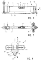
- Figures 1 and 2 show a conventional spirit level 1 as an exemplary measuring device in a preferred Embodiment with the device 2, 3 according to the invention is equipped.
- the spirit level 1 consists of a rod-shaped one Housing 5 of substantially rectangular cross section, in a so-called dragonfly 6 is used.
- the dragonfly is 6 except for a gas bubble 7 filled with a liquid 8, and also clearly visible for the user.
- the spirit level 1 with the device 2, 3 stands up a reference plane 4a, such as a floor, the runs obliquely to the horizontal 4b or is uneven.
- the Spirit level 1 stands on an inclined reference plane 4a the gas bubble 7 is exactly in the middle of the scale 9 of the dragonfly 6, i.e. the spirit level 1 is aligned horizontally and thus leveled exactly parallel to the horizontal 4b.
- the unevenness or Slope of a reference plane 4a can be compensated.
- the reference plane can also be a street, for example or be a landscape area.
- the device according to the invention essentially consists of a first adjusting element 2 and a second adjusting element 3, the two adjusting elements 2, 3 on or in the Close or in the opposite end area lying ends of the rod-shaped housing 5 of the spirit level 1 are attached.
- the housing 5 of the spirit level 1 is in the Adjustment elements 2, 3 described in more detail below inserted and by means of fastening devices 10 and 11 in the adjustment elements 2 and 3 attached so as not to slip to be able to.
- the adjustment elements have clamping devices, that act on the measuring device.
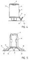
- the first adjusting element 2 is now based on FIGS. 3 to 6 of this embodiment described in more detail. It shows Figure 3 shows the adjusting element 2 in plan view, Figure 4 according Section A-A of Figure 3, Figure 5 in view B of Figure 3 and Figure 6 according to section A-A of Figure 3 with an alternative Fastening device 10 '.
- the first adjusting element 2 consists essentially of a Housing 12, which has the shape of a short hollow profile. Of the Internal cross section of this hollow profile 12 is the cross section of the Measuring device to be accommodated essentially adapted and preferably rectangular according to the shape of the housing 5 of the most common spirit levels 1. Size and cross section of the Housing 12 must be adapted to the spirit level 1 used, the device 2, 3 according to the invention being designed in this way is that spirit levels 1 of different sizes within of a certain area, with one and the same Device 2, 3 can be equipped. This is through the below to be described embodiment of the fastening devices 10, 11 allows.
- the hollow profile 12 has two opposing open ones End faces 13 and 14. There is an open end end 14 at least one stop 15 attached so that the spirit level 1 at one open end 13 inserted into the housing 12 can be until it stops at the other end 15 14 is pending. Instead of an announcement 15 at the open End 14, the housing 12 can also be a closed Have end face 14 against which the spirit level 1 is applied.
- a stop 15 on the housing 12 can also be used entirely can be dispensed with, so that the spirit level 1 is as far in the housing 12 inserted or pushed through the housing 12 can be.
- This alternative grants the user more freedom regarding the position of the first adjustment element 2.
- the orientation of the spirit level 1 the easier and more accurate it is, the closer that is first adjusting element 2 at the front end of the housing 5 of the spirit level 1 is attached.
- the housing 12 is on a stand device or receptacle 16 attached to a secure stand of the adjusting element 2 and thus ensuring the spirit level 1.
- a standing device 16 in the form of a three-point support. With the three-point support 16 there are two feet 18 on the side of the housing 12 at the same axial distance from the longitudinal axis 19 of the spirit level 1 and a base 17 behind the front end of the housing 12 in the extension of the longitudinal axis 19, all three Feet 17, 18 have the same height.
- the two on the side Feet 18 each have a support surface 26, the Stand 17, on the other hand, essentially only one support point 27.
- the spirit level 1 cannot about its longitudinal axis 19 be twisted or tilted.
- the stand device 16 granted but a degree of freedom with respect to rotation about an axis 20 (see FIG. 1), which is at right angles to the axis of rotation 19 in the reference plane 4a or the horizontal 4b through the support point 27 of the support foot 17 extends.
- an axis 20 see FIG. 1
- the spirit level 1 By means of a rotation the spirit level 1 about this axis 20, the spirit level 1 in the horizontal position.
- the fastening device 10 serves the firm seat of the spirit level 1 in the adjusting element 2.
- the Fastening device 10 designed as a U-shaped spring tongue, the base of the "U” is free and the two legs of the "U” are bent down into the interior of the housing 12.
- the spring tongue is thereby formed in one piece with the housing.
- the spirit level 1 pushed into the housing 12 presses the two legs of the spring tongue 10 against their spring force upwards and is clamped by the spring force.
- FIG 6 corresponds to the view of Figure 4 and shows the adjusting element 2 according to section A-A of Figure 3, but with the alternative fastening device 10 'of a screw clamp.
- the screw clamp 10 takes place via a threaded spindle 21 through a corresponding threaded hole 22 in the above lying wall of the housing 12 is guided.
- the threaded spindle 21 is into the housing 12 by means of a handwheel 23 or rotatable out of the housing 12 (arrows 25, 25 ').
- a plate-shaped rubber cap 24 attached at the Tip of the threaded spindle 21 is inside the housing 12 a plate-shaped rubber cap 24 attached.
- the rubber cap 24 causes a larger contact surface of the threaded spindle 21 and avoids damage to the housing 5 of the spirit level 1. Je
- Je There are different size differences depending on the length of the threaded spindle 21 between spirit level housing 5 and housing cross-section bridgeable.
- the fastening device 10, 10 ' can both on the above lying wall of the housing 12, as in FIGS. 3 to 6 shown, and / or on the side walls of the housing 12 for lateral clamping of the spirit level 1.
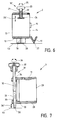
- the second adjusting element 3, the alternative or in addition to first adjustment element can be used is as follows explained in more detail with reference to FIG. 7.
- the one shown in Figure 7 View of the second adjusting element 3 corresponds to that in FIGS Figures 4 and 6 shown section A-A of the first adjusting element 2.
- the top view of the second adjusting element 3 is in can be seen on a smaller scale in FIG.
- the second adjusting element 3 is like the first adjusting element 2 essentially from a housing 28 in the form of a short hollow profile, the main dimensions, in particular of the inner cross section with which the housing 12 of the match first adjusting element 2.
- the housing 28 has a open end 29 into which the spirit level 1 is inserted and a stop 30 on the opposite end 29 of the open end Front end of the housing 28, up to which the spirit level 1 can be inserted into the housing 28.
- the spring tongue 11 is analogous to the spring tongue 10 of the first adjustment element 2 described above, and there are also the alternatives described here, such as a screw clamp.
- the fastening device 11 can on the overhead wall and / or be attached to the side walls of the housing 28.
- an adjusting device 31 Located on the side opposite the open end 29 itself on the housing 28 in the extension of the longitudinal axis 19 the spirit level 1 behind the stop 30 an adjusting device 31.
- the adjusting device 31 is the distance of the second adjusting element 3 adjustable from the reference plane 4a.
- the distance of this front end of the spirit level also becomes 1 set from the reference plane 4a, the spirit level 1 rotated about the axis of rotation 20 shown in FIG and thus aligned parallel to the horizontal 4b can.
- Figure 7 shows the adjusting device 31 as a preferred embodiment in the form of a threaded spindle 32.
- the threaded spindle 32 is in the upper part outside with a smooth Surface and in the lower part with an external thread 33 Mistake.
- the threaded spindle 32 is through two bushings 34, 35 guided on the housing 28, the lower passage 35 with an internal thread corresponding to the threaded spindle 32 is trained.
- By turning the threaded spindle 32 (arrow 36) it is moved up and down in the thread 35, that is moved axially (arrow 36 ') so that by turning the threaded spindle 32 the distance of the second adjusting element 3 from the reference plane 4a is regulated.
- Threaded spindle 32 For easier turning of the threaded spindle 32, this is for the Users on their upper, above the housing 28 End equipped with a handwheel 37. At the bottom of the Threaded spindle 32 is attached to a plastic cap 38 not to damage the surface of the reference plane 4a and the To protect threaded spindle 32.
- the stability of the entire structure 1, 2 and 3 is ensured by the stand device 16 of the first adjusting element 2 and the Positioning of the adjustment device 31 on the line of Longitudinal axis 19 of the spirit level 1 is reached.
- a standing device on the second adjusting element 3 is therefore not necessary, and because the required variable distance from the reference plane 4a also difficult to achieve.
- the plastic caps 24, 38 and the contact surfaces 26 or points 27 of the stand device 16 which are preferably made of plastic, are all Elements of the device 2, 3 according to the invention preferably made of metal, such as steel or aluminum, or also made of plastic.
Landscapes
- Physics & Mathematics (AREA)
- Engineering & Computer Science (AREA)
- General Physics & Mathematics (AREA)
- Radar, Positioning & Navigation (AREA)
- Remote Sensing (AREA)
- Testing Of Balance (AREA)
- Soil Working Implements (AREA)
- Harvester Elements (AREA)
- A Measuring Device Byusing Mechanical Method (AREA)
- Details Of Measuring And Other Instruments (AREA)
- Indication And Recording Devices For Special Purposes And Tariff Metering Devices (AREA)
Abstract
Description
- Figur 1
- eine herkömmliche Wasserwaage mit einer erfindungsgemäßen Vorrichtung in Seitenansicht;
- Figur 2
- eine herkömmliche Wasserwaage mit einer erfindungsgemäßen Vorrichtung in Draufsicht;
- Figur 3
- das erste Justierelement der erfindungsgemäßen Vorrichtung in Draufsicht;
- Figur 4
- das erste Justierelement gemäß Schnitt A-A von Figur 3;
- Figur 5
- das erste Justierelement in Ansicht B von Figur 3;
- Figur 6
- das erste Justierelement gemäß Schnitt A-A von Figur 3 mit einer alternativen Befestigungsvorrichtung; und
- Figur 7
- das zweite Justierelement der erfindungsgemäßen Vorrichtung im Schnitt.
Claims (12)
- Vorrichtung zum Nivellieren von Meßeinrichtungen, insbesondere von Wasserwaagen oder dergleichen,
dadurch gekennzeichnet,
daß zumindest an einem Stirnende oder im Bereich des einen Stirnendes der Meßeinrichtung (1) eine Justiereinrichtung (2, 3) auswechselbar befestigt ist, die ein Justierelement für die Höheneinstellung der Meßeinrichtung von einer Bezugsebene (4a) aufweist. - Vorrichtung nach Anspruch 1,
dadurch gekennzeichnet,
daß die Justiereinrichtung (2, 3) aus einem auf oder an der Meßeinrichtung (1) aufsetzbaren Gehäuse gebildet ist und als Justierelement eine Gewindespindel (32) aufnimmt, deren freies und axial bewegbares Stirnende auf der Bezugsebene (4a) aufsteht. - Vorrichtung nach einem der Ansprüche 1 oder 2,
dadurch gekennzeichnet,
daß an beiden sich gegenüberliegenden Stirnenden oder im Bereich der beiden Stirnenden der Meßeinrichtung (1) jeweils eine Justiereinrichtung (2, 3) auswechselbar befestigt ist, die ein Justierelement für die Höheneinstellung der Meßeinrichtung (1)von einer Bezugsebene aufweist. - Vorrichtung nach einem der Ansprüche 1 bis 3,
dadurch gekennzeichnet,
daß zumindest eine Justiereinrichtung (1)mit einer Dreipunktauflage auf der Bezugsebene (4a)aufsteht. - Vorrichtung nach Anspruch 4,
dadurch gekennzeichnet,
daß die Dreipunktauflage höhenverstellbar ist. - Vorrichtung nach einem der Ansprüche 1 bis 4,
dadurch gekennzeichnet,
daß das Gehäuse der Justiereinrichtung (2, 3)auf der Meßeinrichtung (1) aufsteckbar ist und eine Halteeinrichtung aufweist. - Vorrichtung nach Anspruch 6,
dadurch gekennzeichnet,
daß die Halteeinrichtung eine Federzunge (11) ist, die mit dem Gehäuse verbunden ist. - Vorrichtung nach Anspruch 6,
dadurch gekennzeichnet,
daß die Halteeinrichtung eine Schraubklemmung (10') ist. - Vorrichtung nach Anspruch 6,
dadurch gekennzeichnet,
daß die Halteeinrichtung eine Magnethalterung ist. - Vorrichtung nach Anspruch 6,
dadurch gekennzeichnet,
daß die Halteeinrichtung eine Nut-und-Feder-Klemmung ist. - Vorrichtung nach Anspruch 6,
dadurch gekennzeichnet,
daß die Halteeinrichtung aus einer Sicke, Kerbe, Nut oder dergleichen gebildet ist, in die ein Zapfen, eine Kugel, eine Spitze oder dergleichen einrastet. - Vorrichtung nach Anspruch 4 oder 5,
dadurch gekennzeichnet,
daß ein Fuß der Dreipunktauflage auswechselbar an der Justiereinrichtung (2, 3) befestigt ist.
Applications Claiming Priority (2)
| Application Number | Priority Date | Filing Date | Title |
|---|---|---|---|
| DE29703672U DE29703672U1 (de) | 1997-02-28 | 1997-02-28 | Vorrichtung zum Nivellieren einer Meßeinrichtung |
| DE29703672U | 1997-02-28 |
Publications (3)
| Publication Number | Publication Date |
|---|---|
| EP0862047A2 true EP0862047A2 (de) | 1998-09-02 |
| EP0862047A3 EP0862047A3 (de) | 1999-10-13 |
| EP0862047B1 EP0862047B1 (de) | 2003-01-29 |
Family
ID=8036752
Family Applications (1)
| Application Number | Title | Priority Date | Filing Date |
|---|---|---|---|
| EP97120424A Expired - Lifetime EP0862047B1 (de) | 1997-02-28 | 1997-11-21 | Vorrichtung zum Nivellieren einer Messeinrichtung |
Country Status (3)
| Country | Link |
|---|---|
| EP (1) | EP0862047B1 (de) |
| AT (1) | ATE231963T1 (de) |
| DE (2) | DE29703672U1 (de) |
Cited By (4)
| Publication number | Priority date | Publication date | Assignee | Title |
|---|---|---|---|---|
| GB2437312A (en) * | 2006-04-18 | 2007-10-24 | Karl Mcallister | Adjustable corner gauge |
| US8413343B2 (en) * | 2007-11-05 | 2013-04-09 | Brian K. HALE | Extendable plumb and level measuring device and associated usage method |
| CN113211359A (zh) * | 2021-06-24 | 2021-08-06 | 方盛车桥(柳州)有限公司 | 一种桥壳零件通用自动扶平的方法 |
| CN114034285A (zh) * | 2021-11-04 | 2022-02-11 | 蚌埠高灵传感系统工程有限公司 | 一种基于传感器的高压线塔安全检测设备 |
Families Citing this family (4)
| Publication number | Priority date | Publication date | Assignee | Title |
|---|---|---|---|---|
| DE20209173U1 (de) | 2002-06-12 | 2002-09-19 | Warkotsch, Horst, 30938 Burgwedel | Neigungsmeßvorrichtung zur Ermittlung von Bauteilneigungen insbesondere bei Kraftfahrzeugen |
| US7290346B2 (en) | 2003-08-18 | 2007-11-06 | Kapro Industries, Ltd | Extension set for spirit levels |
| EP1798518A1 (de) * | 2005-12-14 | 2007-06-20 | Kapro Industries ltd. | Universeller Verlängerungssatz für Wasserwaagen |
| CN109352606A (zh) * | 2018-12-04 | 2019-02-19 | 中车洛阳机车有限公司 | 机车大部件安装工装 |
Family Cites Families (5)
| Publication number | Priority date | Publication date | Assignee | Title |
|---|---|---|---|---|
| US2207410A (en) * | 1939-03-29 | 1940-07-09 | Joseph F O'keefe | Device for laying courses and the like |
| DE7228902U (de) * | 1972-02-29 | 1972-11-30 | Heine K | Neigungswasserwaage |
| US4150492A (en) * | 1978-01-09 | 1979-04-24 | Tracy Alan C | Precision level |
| GB2276451A (en) * | 1993-03-24 | 1994-09-28 | Intuitive Designs Limited | Measuring gradients |
| DE9408912U1 (de) * | 1994-05-31 | 1994-09-22 | Zimmermann, Thomas, 80796 München | Wasserwaage |
-
1997
- 1997-02-28 DE DE29703672U patent/DE29703672U1/de not_active Expired - Lifetime
- 1997-11-21 AT AT97120424T patent/ATE231963T1/de not_active IP Right Cessation
- 1997-11-21 EP EP97120424A patent/EP0862047B1/de not_active Expired - Lifetime
- 1997-11-21 DE DE59709230T patent/DE59709230D1/de not_active Expired - Fee Related
Cited By (6)
| Publication number | Priority date | Publication date | Assignee | Title |
|---|---|---|---|---|
| GB2437312A (en) * | 2006-04-18 | 2007-10-24 | Karl Mcallister | Adjustable corner gauge |
| US8413343B2 (en) * | 2007-11-05 | 2013-04-09 | Brian K. HALE | Extendable plumb and level measuring device and associated usage method |
| CN113211359A (zh) * | 2021-06-24 | 2021-08-06 | 方盛车桥(柳州)有限公司 | 一种桥壳零件通用自动扶平的方法 |
| CN113211359B (zh) * | 2021-06-24 | 2022-07-26 | 方盛车桥(柳州)有限公司 | 一种桥壳零件通用自动扶平的方法 |
| CN114034285A (zh) * | 2021-11-04 | 2022-02-11 | 蚌埠高灵传感系统工程有限公司 | 一种基于传感器的高压线塔安全检测设备 |
| CN114034285B (zh) * | 2021-11-04 | 2022-08-02 | 蚌埠高灵传感系统工程有限公司 | 一种基于传感器的高压线塔安全检测设备 |
Also Published As
| Publication number | Publication date |
|---|---|
| DE59709230D1 (de) | 2003-03-06 |
| DE29703672U1 (de) | 1998-06-25 |
| EP0862047A3 (de) | 1999-10-13 |
| EP0862047B1 (de) | 2003-01-29 |
| ATE231963T1 (de) | 2003-02-15 |
Similar Documents
| Publication | Publication Date | Title |
|---|---|---|
| EP1126239B1 (de) | Wasserwaage | |
| CH688290A5 (de) | Wasserwaage. | |
| EP0862047B1 (de) | Vorrichtung zum Nivellieren einer Messeinrichtung | |
| DE102017000491A1 (de) | Schweißnahtlehre zur Messung der Abmessungen einer Schweißnaht | |
| DE8707409U1 (de) | Türschließer mit einer Schließkraft-Anzeigevorrichtung | |
| WO1999046561A1 (de) | Wasserwaage | |
| DE69404331T2 (de) | Oberflächeniveaukontrollapparat | |
| DE19503408A1 (de) | Bau- bzw. Handwerkerschablone | |
| DE202011000407U1 (de) | Nivellierhilfe | |
| DE29700222U1 (de) | Nivelliergerät | |
| DE3400392C2 (de) | Vorrichtung zum Festlegen von Meßpunkten und zur Festlegung von Abständen und Richtungen | |
| DE102004055320A1 (de) | Vorrichtung zur Positionierung eines länglichen Bauteils | |
| DE102009010832B4 (de) | Montagevorrichtung und Montageverfahren für Tür- und/oder Fensterzargen | |
| DE4128472A1 (de) | Hilfsvorrichtung zum genauen waagerechten bzw. senkrechten Anbringen von wenigstens zwei im Abstand voneinander liegenden Befestigungsmitteln an einer Wand oder dergleichen | |
| DE29919446U1 (de) | Haltevorrichtung für eine Deckenrandschalung | |
| DE202022101252U1 (de) | Wasserwaage | |
| DE29703026U1 (de) | Vorrichtung zum Abstecken einer horizontalen Ebene mittels Wasserwaage | |
| DE10216090A1 (de) | Wasserwaage für Fensterbänke | |
| DE10214881A1 (de) | Verfahren zur Ausrichtung und/oder Anordnung von Bauelementen | |
| DE29714707U1 (de) | Wasserwaage | |
| DE9403772U1 (de) | Anschlagwinkel mit Streich- und Tiefenmaß | |
| DE9404842U1 (de) | Vorrichtung zum Abschranken einer Gebäudeöffnung | |
| DE29605049U1 (de) | Neigungsmeßinstrument | |
| DE8400153U1 (de) | Schnurgeruestreflektorhalter | |
| DE3818895A1 (de) | Doppelbodenplatte und stuetze dazu |
Legal Events
| Date | Code | Title | Description |
|---|---|---|---|
| PUAI | Public reference made under article 153(3) epc to a published international application that has entered the european phase |
Free format text: ORIGINAL CODE: 0009012 |
|
| AK | Designated contracting states |
Kind code of ref document: A2 Designated state(s): AT BE CH DE DK ES FR GB IT LI NL |
|
| AX | Request for extension of the european patent |
Free format text: AL;LT;LV;MK;RO;SI |
|
| PUAL | Search report despatched |
Free format text: ORIGINAL CODE: 0009013 |
|
| AK | Designated contracting states |
Kind code of ref document: A3 Designated state(s): AT BE CH DE DK ES FI FR GB GR IE IT LI LU MC NL PT SE |
|
| AX | Request for extension of the european patent |
Free format text: AL;LT;LV;MK;RO;SI |
|
| 17P | Request for examination filed |
Effective date: 19991030 |
|
| AKX | Designation fees paid |
Free format text: AT BE CH DE DK ES FR GB IT LI NL |
|
| 17Q | First examination report despatched |
Effective date: 20010425 |
|
| GRAG | Despatch of communication of intention to grant |
Free format text: ORIGINAL CODE: EPIDOS AGRA |
|
| GRAG | Despatch of communication of intention to grant |
Free format text: ORIGINAL CODE: EPIDOS AGRA |
|
| GRAH | Despatch of communication of intention to grant a patent |
Free format text: ORIGINAL CODE: EPIDOS IGRA |
|
| GRAH | Despatch of communication of intention to grant a patent |
Free format text: ORIGINAL CODE: EPIDOS IGRA |
|
| GRAH | Despatch of communication of intention to grant a patent |
Free format text: ORIGINAL CODE: EPIDOS IGRA |
|
| GRAA | (expected) grant |
Free format text: ORIGINAL CODE: 0009210 |
|
| AK | Designated contracting states |
Designated state(s): AT BE CH DE DK ES FR GB IT LI NL |
|
| PG25 | Lapsed in a contracting state [announced via postgrant information from national office to epo] |
Ref country code: NL Free format text: LAPSE BECAUSE OF FAILURE TO SUBMIT A TRANSLATION OF THE DESCRIPTION OR TO PAY THE FEE WITHIN THE PRESCRIBED TIME-LIMIT Effective date: 20030129 Ref country code: IT Free format text: LAPSE BECAUSE OF FAILURE TO SUBMIT A TRANSLATION OF THE DESCRIPTION OR TO PAY THE FEE WITHIN THE PRE;WARNING: LAPSES OF ITALIAN PATENTS WITH EFFECTIVE DATE BEFORE 2007 MAY HAVE OCCURRED AT ANY TIME BEFORE 2007. THE CORRECT EFFECTIVE DATE MAY BE DIFFERENT FROM THE ONE RECORDED.SCRIBED TIME-LIMIT Effective date: 20030129 Ref country code: GB Free format text: LAPSE BECAUSE OF FAILURE TO SUBMIT A TRANSLATION OF THE DESCRIPTION OR TO PAY THE FEE WITHIN THE PRESCRIBED TIME-LIMIT Effective date: 20030129 |
|
| REG | Reference to a national code |
Ref country code: GB Ref legal event code: FG4D Free format text: NOT ENGLISH |
|
| REG | Reference to a national code |
Ref country code: CH Ref legal event code: EP |
|
| REF | Corresponds to: |
Ref document number: 59709230 Country of ref document: DE Date of ref document: 20030306 Kind code of ref document: P |
|
| PG25 | Lapsed in a contracting state [announced via postgrant information from national office to epo] |
Ref country code: DK Free format text: LAPSE BECAUSE OF FAILURE TO SUBMIT A TRANSLATION OF THE DESCRIPTION OR TO PAY THE FEE WITHIN THE PRESCRIBED TIME-LIMIT Effective date: 20030429 |
|
| NLV1 | Nl: lapsed or annulled due to failure to fulfill the requirements of art. 29p and 29m of the patents act | ||
| GBV | Gb: ep patent (uk) treated as always having been void in accordance with gb section 77(7)/1977 [no translation filed] |
Effective date: 20030129 |
|
| PG25 | Lapsed in a contracting state [announced via postgrant information from national office to epo] |
Ref country code: ES Free format text: LAPSE BECAUSE OF FAILURE TO SUBMIT A TRANSLATION OF THE DESCRIPTION OR TO PAY THE FEE WITHIN THE PRESCRIBED TIME-LIMIT Effective date: 20030730 |
|
| ET | Fr: translation filed | ||
| PG25 | Lapsed in a contracting state [announced via postgrant information from national office to epo] |
Ref country code: AT Free format text: LAPSE BECAUSE OF NON-PAYMENT OF DUE FEES Effective date: 20031121 |
|
| PG25 | Lapsed in a contracting state [announced via postgrant information from national office to epo] |
Ref country code: LI Free format text: LAPSE BECAUSE OF NON-PAYMENT OF DUE FEES Effective date: 20031130 Ref country code: CH Free format text: LAPSE BECAUSE OF NON-PAYMENT OF DUE FEES Effective date: 20031130 Ref country code: BE Free format text: LAPSE BECAUSE OF NON-PAYMENT OF DUE FEES Effective date: 20031130 |
|
| PLBE | No opposition filed within time limit |
Free format text: ORIGINAL CODE: 0009261 |
|
| STAA | Information on the status of an ep patent application or granted ep patent |
Free format text: STATUS: NO OPPOSITION FILED WITHIN TIME LIMIT |
|
| 26N | No opposition filed |
Effective date: 20031030 |
|
| BERE | Be: lapsed |
Owner name: *MAYER & WONISCH G.M.B.H. & CO. K.G. Effective date: 20031130 |
|
| REG | Reference to a national code |
Ref country code: CH Ref legal event code: PL |
|
| PGFP | Annual fee paid to national office [announced via postgrant information from national office to epo] |
Ref country code: DE Payment date: 20051109 Year of fee payment: 9 |
|
| PGFP | Annual fee paid to national office [announced via postgrant information from national office to epo] |
Ref country code: FR Payment date: 20051123 Year of fee payment: 9 |
|
| PG25 | Lapsed in a contracting state [announced via postgrant information from national office to epo] |
Ref country code: DE Free format text: LAPSE BECAUSE OF NON-PAYMENT OF DUE FEES Effective date: 20070601 |
|
| REG | Reference to a national code |
Ref country code: FR Ref legal event code: ST Effective date: 20070731 |
|
| PG25 | Lapsed in a contracting state [announced via postgrant information from national office to epo] |
Ref country code: FR Free format text: LAPSE BECAUSE OF NON-PAYMENT OF DUE FEES Effective date: 20061130 |