EP0862065A2 - Détecteur à alarme et dispositif d'antenne - Google Patents
Détecteur à alarme et dispositif d'antenne Download PDFInfo
- Publication number
- EP0862065A2 EP0862065A2 EP98300287A EP98300287A EP0862065A2 EP 0862065 A2 EP0862065 A2 EP 0862065A2 EP 98300287 A EP98300287 A EP 98300287A EP 98300287 A EP98300287 A EP 98300287A EP 0862065 A2 EP0862065 A2 EP 0862065A2
- Authority
- EP
- European Patent Office
- Prior art keywords
- accordance
- antennae
- antenna arrangement
- signals
- vehicle
- Prior art date
- Legal status (The legal status is an assumption and is not a legal conclusion. Google has not performed a legal analysis and makes no representation as to the accuracy of the status listed.)
- Withdrawn
Links
Images



Classifications
-
- G—PHYSICS
- G01—MEASURING; TESTING
- G01S—RADIO DIRECTION-FINDING; RADIO NAVIGATION; DETERMINING DISTANCE OR VELOCITY BY USE OF RADIO WAVES; LOCATING OR PRESENCE-DETECTING BY USE OF THE REFLECTION OR RERADIATION OF RADIO WAVES; ANALOGOUS ARRANGEMENTS USING OTHER WAVES
- G01S13/00—Systems using the reflection or reradiation of radio waves, e.g. radar systems; Analogous systems using reflection or reradiation of waves whose nature or wavelength is irrelevant or unspecified
- G01S13/02—Systems using reflection of radio waves, e.g. primary radar systems; Analogous systems
- G01S13/50—Systems of measurement based on relative movement of target
- G01S13/52—Discriminating between fixed and moving objects or between objects moving at different speeds
- G01S13/56—Discriminating between fixed and moving objects or between objects moving at different speeds for presence detection
-
- B—PERFORMING OPERATIONS; TRANSPORTING
- B60—VEHICLES IN GENERAL
- B60R—VEHICLES, VEHICLE FITTINGS, OR VEHICLE PARTS, NOT OTHERWISE PROVIDED FOR
- B60R25/00—Fittings or systems for preventing or indicating unauthorised use or theft of vehicles
- B60R25/10—Fittings or systems for preventing or indicating unauthorised use or theft of vehicles actuating a signalling device
- B60R25/1004—Alarm systems characterised by the type of sensor, e.g. current sensing means
- B60R25/1009—Sonic sensors; Signal treatment therefor
Definitions
- the present invention relates to an alarm sensor and more particularly, although not exclusively, to an alarm sensor suitable for use in a microwave frequency vehicle intruder alarm.
- Another aspect of the present invention relates to an antenna arrangement for use in a vehicle intruder alarm.
- Microwave ovens typically employ a cavity magnetron source, the frequency of which will vary as the load VSWR within the oven changes due to rotation of the turntable or mode-stirrer paddle.
- microwave alarm sensors operating in the 2.45 GHz ISM band can often be subjected to strong interference, traversing their operating frequency.
- Microwave ovens also tend to have poorly filtered and regulated power supplies. This typically results in wideband am and fm signals extending several hundred MHZ either side of the centre frequency. These sidebands contain the fundamental mains frequency and many higher order harmonic frequencies.
- modulation phenomena can cause false triggering of low power microwave alarm sensors in two ways. Firstly, the sensor can mistake rectified am sidebands as a Doppler shifted reflection, i.e. as a moving target. Secondly, especially in single antenna systems such as that described in GB-A-2280558, an oscillator of the sensor can injection lock to the frequency of the powerful interfering signal. In this instance, the sensor will be triggered as the oscillator becomes locked or as it unlocks itself.
- an alarm sensor in which a microwave frequency signal is transmitted to illuminate a volume, reflected by surfaces within that volume and received by an antenna, comprising means to detect signals within a first frequency band, means to determine whether said detected signals are indicative of the presence of a source of interference, and means, responsive to said determining means, to control an output of the alarm sensor.
- an antenna for use in a vehicle intruder alarm comprising a power divider arranged to provide at least two patch antennae with a common signal, the antennae being arranged to radiate a field having a section which is predetermined in shape by the interaction of said patch antennae.
- said shape is substantially rectangular.
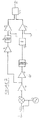
- an alarm sensor 20A which operates to mute its output in the presence of microwave oven generated interference.
- An oscillator 3 generates a RF signal which is fed to both of an antenna (not shown) connected to an antenna terminal 1 through a coupler 17, and a mixer 2.
- Mixer 2 therefore mixes the signal from the oscillator 3 with a reflected signal received by the antenna (not shown).
- An amplifier 4 amplifies the output signal of the mixer 2.
- a variable gain amplifier 5 further amplifies the signal, under control of a signal on a terminal 6, which is then filtered by a low pass filter 7.
- the signal is split into two branches.
- the first branch is made up of a rectifier 12 and a comparator 13.
- the rectifier 12 is preferably an active precision rectifier which is able to accommodate low-level signals at its input.
- the output of the rectifier 12 is compared with a reference potential, applied to a terminal 14, by the comparator 13.
- This first branch operates to detect when the output of the filter 7 shows there to be an amount of non-carrier microwave signals above a predetermined amplitude threshold.
- This first branch is much the same as that described in GB-A-2280558.
- the second branch is made up of an amplifier 8, a high pass filter 9 and a comparator 10.
- the signal from filter 7 is amplified by amplifier 8, and then filtered by the filter 9, to remove the low frequency signals.
- the resultant signal is then compared with a reference voltage, applied to a terminal 11, by a comparator 10.
- the filter 7 has a cut-off frequency of about 200 Hz and the filter 9 has a cut-off frequency of 40 Hz.
- the bandwidth of sensor 20A is very limited, relative to the high RF frequencies involved, but is still much higher than the bandwidth needed for moving target detection.
- the second branch is able to detect the level of the signal which is characteristic of the am sidebands of microwave ovens. This is used as a measurement of oven interference, which is compared to a predetermined threshold by the comparator 10.
- the comparator 10 determines that there is a sufficiently high signal level in the 40-200 Hz band, it sends its output high, indicating the presence of the characteristics of microwave oven generated interference.
- the output signals of comparators 10 and 13 are applied to a logic element 15.
- the logic element 15 generates an output pulse only when the comparator 13 has a high output and the comparator 10 has a low output. In this way, the sensor output is muted in the presence of the characteristic modulation signature of a microwave oven.
- the rectifier 12 preferably includes a charge pump. This charge pump will cause a time delay of approximately 100 ms in the first branch, thereby allowing the second branch some time to react to oven generated interference.
- the rectifier 12 and the comparator 13 could be replaced by a window comparator (not shown), this achieving the same effect but at a lower cost.
- the sensor arrangement 20B comprises the same elements as the Figure 1 sensor 20A, from which Figure reference numerals have been retained.
- the filter 9 has a cut-off frequency of 50 Hz and the filter 7 has a cut-off frequency of 40 Hz.
- the sensor 20B is operable to determine when signals in the 0-40 Hz frequency band exceed a predetermined amplitude threshold by way of the comparator 13, and uses this detection to indicate alarmable conditions. Signals indicative of the presence of externally generated interference are detected by the comparator 10, which receives only signals having frequencies of 50 Hz or more.
- the logic element 15 is operable to mute the sensor output 16 in the presence of sufficiently strong signals in the 50+ Hz frequency band.
- the sensor 20B can be arranged to be sensitive to interference signals over a larger range of frequencies than the sensor 20A.
- an antennae arrangement 35 is shown in accordance with a second aspect of the invention.
- the antenna arrangement 35 comprises first and second patch antennae 21, 22 and a power divider, formed by components 30 - 33.
- the patch antennae 21, 22 are formed by the deposition of a thin layer of an electrically conductive material, preferably a metal, on one surface of a circuit board.
- a ground plane (not shown) is located on the other side of the circuit board to the antenna 21, 22.
- the antennae 21, 22 are connected to an input connector 34 by way of two metal vias (not shown), connecting pad 23 to pad 24 and pad 27 to pad 28 respectively, connecting arms 25, 26, resistive elements 30, 31, 32 and a conductor 33.
- the resistive elements 30, 31, 32 allow equal division of the transmitter power front an input connector 34 between the antennae 21, 22.
- the resistance of each of the elements 30, 31 and 32 is preferably about 100 ⁇ .
- a capacitor 29 is optionally connected between connecting arm 25 and ground potential to cause a phase difference in the signals at respective ones of the antennae 21, 22.
- the patch antennae 21, 22 are rectangular in shape and are separated by a distance of 8 mm at their shortest sides.
- the antennae are preferably 20 mm by 30 mm and are separated from the ground plane by a distance of 1.5 mm, although the dimensions of the antennae depend on the shape of the desired field and the operating frequency.
- the inventors have found that this arrangement provides a rectangular field which, when placed on the ceiling of a vehicle, provides near perfect coverage of that vehicle. This is shown schematically in Figures 3A and 3B.
- an alarm arrangement 40 comprises both the antennae arrangement 35 of Figure 3 and the alarm sensor 20A of Figure 1 or the sensor 20B Figure 2.
- the arrangement 40 is mounted either directly on the underside of the roof of a vehicle 42, or is suspended from roof lining thereattached. In the former case, a removable cover is preferably provided within the roof lining, to provide access to the arrangement 40 for servicing purposes.
- the radiation field within the vehicle 42 is shown by the hatched area 41.
- the dimensions of the antennae arrangement 35 are such that the resulting field is about one and a half times as long as it is wide. In this way, the antennae 21, 22 ensure illumination of the entire interior of the vehicle whilst avoiding illumination of the exterior.
- the dimensions needed for an arrangement suitable for providing coverage of, for example, an MPV or a minibus could be easily calculated by a skilled person.
- the radiation field generated by the antennae 21, 22 is able to be steered in accordance with a preferred feature of the present invention, allowing the arrangement 40 to be mounted off-centre in the roof of the vehicle 42 whilst still providing reasonable illumination of the vehicle's interior.
- This is achieved in the Figure 3 arrangement by the connection of the capacitor 29.
- the capacitor 29 causes a change of phase in the signal reaching the antenna 21 from the input connector 34, so causing the antennae 21 and 22 to transmit out of phase signals.
- steering of the radiation field is achieved, the degree of steering being determined by the value of the capacitor 29.
- the capacitor 29 could be replaced by an inductor (not shown) which would similarly provide a phase change in the signals reaching the first antenna 21.
- an inductor not shown
- one or both of these elements could be series connected in either or both of the connecting arms 25, 26.
- connection arms 25 and 26 could also be achieved by having the connection arms 25 and 26 formed of different lengths although this is unfavourable as it allows less flexibility in sensor design.
- the antennae 21, 22 could be centre fed, instead of edge fed, to save space and minimise the size of the arrangement 40, although this would require the use of multilayer boards.
- an antenna arrangement 35 having four patch antennae In this way, a radiation field generated thereby can be steered in two planes, allowing reasonable illumination of a vehicle's interior to be provided from an arrangement 40 mounted, for example, in one corner of its roof.
- Such an arrangement could be used to advantage where mountability in the roof space is restricted by, for example, the folding nature of a soft-roofed convertible car.
- the use of four antennae also allows a radiation field to be narrowed. The narrowing occurs in the plane of polarisation.
- FIG. 5 shows one way in which the arrangement 40 may be organised.
- the arrangement 40 comprises a circuitry container 43, which contains circuit boards or integrated circuits implementing the Figure 1 alarm sensor 20A or the Figure 2 alarm sensor 20B, a printed circuit board 44 and the antenna arrangement 35 of Figure 3.
- the antennae arrangement 35 is electrically connected to the circuitry container 43 through vias 45 in the printed circuit board 44.
- the circuitry container 43 preferably comprises a metal can effective to shield the circuit boards or integrated circuits contained therein from radiation generated by the antennae arrangement 35 and from radiation generated externally.
- the metal can also prevents electromagnetic radiation, such as for example radiation resulting from oscillator harmonic signals, from the sensor 20 being radiated into the surrounding environment.
- the arrangement 40 thus provided can be of such dimensions as to be unobtrusive when mounted in the roof of a vehicle, yet provide reasonable illumination of that vehicle's interior.
Landscapes
- Engineering & Computer Science (AREA)
- Radar, Positioning & Navigation (AREA)
- Remote Sensing (AREA)
- Mechanical Engineering (AREA)
- Computer Networks & Wireless Communication (AREA)
- Physics & Mathematics (AREA)
- General Physics & Mathematics (AREA)
- Burglar Alarm Systems (AREA)
- Support Of Aerials (AREA)
- Geophysics And Detection Of Objects (AREA)
- Waveguide Aerials (AREA)
Applications Claiming Priority (2)
| Application Number | Priority Date | Filing Date | Title |
|---|---|---|---|
| GB9702242 | 1997-02-04 | ||
| GBGB9702242.0A GB9702242D0 (en) | 1997-02-04 | 1997-02-04 | Alarm sensor and antenna arrangement |
Publications (2)
| Publication Number | Publication Date |
|---|---|
| EP0862065A2 true EP0862065A2 (fr) | 1998-09-02 |
| EP0862065A3 EP0862065A3 (fr) | 1998-12-23 |
Family
ID=10807055
Family Applications (1)
| Application Number | Title | Priority Date | Filing Date |
|---|---|---|---|
| EP98300287A Withdrawn EP0862065A3 (fr) | 1997-02-04 | 1998-01-15 | Capteur d'alarme et système d'antennes |
Country Status (4)
| Country | Link |
|---|---|
| US (1) | US5999090A (fr) |
| EP (1) | EP0862065A3 (fr) |
| JP (1) | JPH10247289A (fr) |
| GB (1) | GB9702242D0 (fr) |
Cited By (2)
| Publication number | Priority date | Publication date | Assignee | Title |
|---|---|---|---|---|
| EP1031853A3 (fr) * | 1999-02-27 | 2001-04-25 | Delphi Technologies, Inc. | Capteurs et système radar pour surveillance d'un espace |
| WO2008084249A1 (fr) * | 2007-01-12 | 2008-07-17 | E2V Technologies (Uk) Limited | Structure d'antenne |
Families Citing this family (5)
| Publication number | Priority date | Publication date | Assignee | Title |
|---|---|---|---|---|
| JP4134751B2 (ja) * | 2003-02-26 | 2008-08-20 | 株式会社日本自動車部品総合研究所 | 侵入センサ用アンテナ |
| GB2415557A (en) * | 2004-04-02 | 2005-12-28 | Scorpion Vehicle Security Syst | Microwave based intrusion detection system for use in a vehicle |
| US20080246608A1 (en) * | 2007-04-06 | 2008-10-09 | Chen-Kuei Hsieh | Multi-functional burglar-proof lockset assembly structure |
| US20080245118A1 (en) * | 2007-04-06 | 2008-10-09 | Chen-Kuei Hsieh | Multi-functional burglar-proof lockset assembly structure |
| CN203434265U (zh) * | 2013-04-19 | 2014-02-12 | 深圳市海骏电子科技有限公司 | 一种平面天线微波模块及智能控制节能灯 |
Family Cites Families (28)
| Publication number | Priority date | Publication date | Assignee | Title |
|---|---|---|---|---|
| US3665443A (en) * | 1970-09-03 | 1972-05-23 | Aerospace Res | Ultrasonic intrusion alarm |
| US3728721A (en) * | 1971-01-28 | 1973-04-17 | Mosler Safe Co | Differential doppler detection for rf intruder alarm systems |
| GB1336255A (en) * | 1971-03-19 | 1973-11-07 | Shorrock Dev | Micro-wave intruder detector systems |
| US3803623A (en) * | 1972-10-11 | 1974-04-09 | Minnesota Mining & Mfg | Microstrip antenna |
| US3921177A (en) * | 1973-04-17 | 1975-11-18 | Ball Brothers Res Corp | Microstrip antenna structures and arrays |
| US3922660A (en) * | 1974-12-12 | 1975-11-25 | American District Telegraph Co | Volumetric intrusion alarm using both Doppler and net-change signal processing |
| DE2613845C3 (de) * | 1976-03-31 | 1979-06-28 | Siemens Ag, 1000 Berlin Und 8000 Muenchen | Die Dopplerverschiebung der Rflexion von elektromagnetischer und Ultraschall-Strahlung auswertendes Einbruchalarmgerät |
| CA1084618A (fr) * | 1976-11-10 | 1980-08-26 | Martin T. Cole | Detecteur de mouvement sensible a la difference de phase |
| GB1529541A (en) * | 1977-02-11 | 1978-10-25 | Philips Electronic Associated | Microwave antenna |
| US4117466A (en) * | 1977-03-14 | 1978-09-26 | Lichtblau G J | Beat frequency interference rejection circuit |
| US4458240A (en) * | 1978-12-26 | 1984-07-03 | The United States Of America As Represented By The Secretary Of The Army | Energy wave electronic intruder detection system |
| DE2900444A1 (de) * | 1979-01-08 | 1980-07-10 | Licentia Gmbh | Verfahren und schaltungsanordnung zur auswertung von ausgangssignalen von schallaufnehmern einer objektschutzueberwachungsanlage und zur erzeugung eines alarmsignals |
| GB2108301B (en) * | 1981-08-17 | 1985-06-19 | Munford And White Limited | Intruder alarm device |
| DE3208789A1 (de) * | 1982-03-11 | 1983-09-22 | Standard Elektrik Lorenz Ag, 7000 Stuttgart | Antenne mit mindestens einem dipol |
| GB2120491B (en) * | 1982-04-21 | 1985-06-26 | Racal Security Ltd | Improvements in and relating to signal transmitting and receiving arrangements |
| CH667343A5 (de) * | 1984-02-13 | 1988-09-30 | Cerberus Ag | Verfahren und schaltungsanordnung zur funktionskontrolle von ultraschall-alarmanlagen. |
| DE3704893A1 (de) * | 1987-02-17 | 1988-08-25 | Turck Werner Kg | Anordnung fuer naeherungsschalter zum schutz gegen signalverfaelschung durch magnetische wechselfelder |
| GB2230776A (en) * | 1989-04-27 | 1990-10-31 | Shell Int Research | N-Substituted thiazole-5-carboximidate and -thiocarboximidate derivatives |
| GB8919963D0 (en) * | 1989-09-04 | 1990-01-04 | Marconi Co Ltd | Intruder alarm system |
| GB2244381A (en) * | 1990-05-23 | 1991-11-27 | Philips Electronic Associated | Microstrip patch antenna |
| GB9026037D0 (en) * | 1990-11-30 | 1991-01-16 | Marconi Gec Ltd | Motion detector unit |
| US5315303A (en) * | 1991-09-30 | 1994-05-24 | Trw Inc. | Compact, flexible and integrated millimeter wave radar sensor |
| JP2585888Y2 (ja) * | 1991-11-28 | 1998-11-25 | 株式会社岩田エレクトリック | 自動車の盗難等感知器 |
| JP2840493B2 (ja) * | 1991-12-27 | 1998-12-24 | 株式会社日立製作所 | 一体型マイクロ波回路 |
| US5396217A (en) * | 1993-02-01 | 1995-03-07 | General Motors Corporation | Phase shift analysis for vehicle intrusion detection |
| US5581237A (en) * | 1994-10-26 | 1996-12-03 | Detection Systems, Inc. | Microwave intrusion detector with threshold adjustment in response to periodic signals |
| GB2300776A (en) * | 1995-05-10 | 1996-11-13 | Plessey Semiconductors Ltd | Car alarm |
| GB2302773B (en) * | 1995-06-29 | 1999-12-22 | Pyronix Ltd | Improvements in or relating to motion detection units |
-
1997
- 1997-02-04 GB GBGB9702242.0A patent/GB9702242D0/en active Pending
-
1998
- 1998-01-13 US US09/006,520 patent/US5999090A/en not_active Expired - Fee Related
- 1998-01-15 EP EP98300287A patent/EP0862065A3/fr not_active Withdrawn
- 1998-02-03 JP JP3666898A patent/JPH10247289A/ja active Pending
Cited By (2)
| Publication number | Priority date | Publication date | Assignee | Title |
|---|---|---|---|---|
| EP1031853A3 (fr) * | 1999-02-27 | 2001-04-25 | Delphi Technologies, Inc. | Capteurs et système radar pour surveillance d'un espace |
| WO2008084249A1 (fr) * | 2007-01-12 | 2008-07-17 | E2V Technologies (Uk) Limited | Structure d'antenne |
Also Published As
| Publication number | Publication date |
|---|---|
| JPH10247289A (ja) | 1998-09-14 |
| US5999090A (en) | 1999-12-07 |
| EP0862065A3 (fr) | 1998-12-23 |
| GB9702242D0 (en) | 1997-03-26 |
Similar Documents
| Publication | Publication Date | Title |
|---|---|---|
| EP0535780B1 (fr) | Capteur radar à ondes millimétriques, intégré compact et à multiusage | |
| US5512901A (en) | Built-in radiation structure for a millimeter wave radar sensor | |
| JP4268202B2 (ja) | 自動車用前方監視センサ | |
| EP1462822A1 (fr) | Radar mobile a onde millimetrique | |
| KR100776868B1 (ko) | 레이더 수신기를 위한 비디오 증폭기 | |
| JP2008511006A (ja) | レーダ高度計 | |
| WO2001026948B1 (fr) | Reglage de pale a microonde | |
| US5999090A (en) | Alarm sensor and antenna arrangement | |
| US5563617A (en) | Doppler microwave sensor | |
| US7079029B2 (en) | Dual-frequency microwave sensor | |
| NL9001414A (nl) | Radarapparaat met storingsindicator en ontvanginrichting met storingsindicator. | |
| GB2322029A (en) | Microwave vehicle alarm | |
| GB2152759A (en) | Antenna device for direction finders | |
| JP4532509B2 (ja) | 車載電波レーダ装置 | |
| KR910000108B1 (ko) | 고주파 도난 방지 장치 | |
| Ho et al. | A compact 24 GHz radar sensor for vehicle sideway-looking applications | |
| US20060049979A1 (en) | Device for transmitting and receiving radar radiation | |
| EP1422533B1 (fr) | Récepteur et système radar | |
| JP2003207561A (ja) | レーダ動作監視システム | |
| KR20220147456A (ko) | 특정 대역 전자기파를 차단하는 마이크로웨이브 센서 및 이를 구비한 조명 장치 | |
| JPH09178835A (ja) | ドップラーレーダモジュールの周波数混合器 | |
| JP2007124565A (ja) | マイクロ波ドップラーセンサ | |
| Baba et al. | Doppler Radar Speed Sensor for Anti-Skid Control System | |
| WO2007132455A2 (fr) | Émetteur-rÉcepteur de micro-ondes de vÉhicule | |
| 김영수 et al. | Short Range Rear Obstacle Detector for Automobile by using 24㎓ AM Radar Sensor |
Legal Events
| Date | Code | Title | Description |
|---|---|---|---|
| PUAI | Public reference made under article 153(3) epc to a published international application that has entered the european phase |
Free format text: ORIGINAL CODE: 0009012 |
|
| AK | Designated contracting states |
Kind code of ref document: A2 Designated state(s): DE FR NL SE |
|
| AX | Request for extension of the european patent |
Free format text: AL;LT;LV;MK;RO;SI |
|
| RAP1 | Party data changed (applicant data changed or rights of an application transferred) |
Owner name: MITEL SEMICONDUCTOR LIMITED |
|
| PUAL | Search report despatched |
Free format text: ORIGINAL CODE: 0009013 |
|
| AK | Designated contracting states |
Kind code of ref document: A3 Designated state(s): AT BE CH DE DK ES FI FR GB GR IE IT LI LU MC NL PT SE |
|
| AX | Request for extension of the european patent |
Free format text: AL;LT;LV;MK;RO;SI |
|
| 17P | Request for examination filed |
Effective date: 19990514 |
|
| AKX | Designation fees paid |
Free format text: DE FR NL SE |
|
| 17Q | First examination report despatched |
Effective date: 20000915 |
|
| RAP1 | Party data changed (applicant data changed or rights of an application transferred) |
Owner name: DYNEX SEMICONDUCTOR LIMITED |
|
| STAA | Information on the status of an ep patent application or granted ep patent |
Free format text: STATUS: THE APPLICATION IS DEEMED TO BE WITHDRAWN |
|
| 18D | Application deemed to be withdrawn |
Effective date: 20020801 |