EP0862072A2 - Klemmringe und Struktur zum Abschluss optischer Fasern - Google Patents
Klemmringe und Struktur zum Abschluss optischer Fasern Download PDFInfo
- Publication number
- EP0862072A2 EP0862072A2 EP98301460A EP98301460A EP0862072A2 EP 0862072 A2 EP0862072 A2 EP 0862072A2 EP 98301460 A EP98301460 A EP 98301460A EP 98301460 A EP98301460 A EP 98301460A EP 0862072 A2 EP0862072 A2 EP 0862072A2
- Authority
- EP
- European Patent Office
- Prior art keywords
- optical fibre
- annular portion
- ferrule
- rear end
- periphery
- Prior art date
- Legal status (The legal status is an assumption and is not a legal conclusion. Google has not performed a legal analysis and makes no representation as to the accuracy of the status listed.)
- Withdrawn
Links
Images


Classifications
-
- G—PHYSICS
- G02—OPTICS
- G02B—OPTICAL ELEMENTS, SYSTEMS OR APPARATUS
- G02B6/00—Light guides; Structural details of arrangements comprising light guides and other optical elements, e.g. couplings
- G02B6/24—Coupling light guides
- G02B6/36—Mechanical coupling means
- G02B6/38—Mechanical coupling means having fibre to fibre mating means
- G02B6/3807—Dismountable connectors, i.e. comprising plugs
- G02B6/3887—Anchoring optical cables to connector housings, e.g. strain relief features
- G02B6/3888—Protection from over-extension or over-compression
Definitions
- the present invention relates to clamp rings such as those used in optical connectors which are located between optical fibre transmission lines for switching, connecting or disconnecting the transmission lines and those directly fitted to ferrules, as well as to optical fibre terminating structures.
- detachable optical connectors are used for connecting optical fibre cables and optical fibre cords intended for short-distance applications such as in-building wiring and wiring to equipment. Since optical fibres are so thin and flexible they are usually secured by using ferrules.
- An optical connector is constructed of a plug incorporating a ferrule and an adaptor incorporating a sleeve.
- FIG. 6 shows a cross section of an optical connector employing a conventional crimp ring.
- a ferrule 101 in which an optical fibre 201 is inserted and fixed has a flange 102.
- a stopper 104a is fitted behind a rear end portion of the ferrule 101 in the back of the flange 102 with a compression spring 103.
- Spring 103 is mounted on the outer periphery of the rear end portion of the ferrule 101. This means that the ferrule 102 is fitted in such a way that it can move relative to the stopper 104a in its axial direction, with the aid of the compression spring 103.
- a coated optical fibre 202 is inserted into the compression spring 103 and the stopper 104a.
- a tensile strength member 204 of an optical fibre cable 203 is located at the rear end of the stopper 104b.
- the tensile strength member 204 is secured around the outer periphery of a rear end portion of the stopper 104b by crimping a crimp ring 105.
- the crimp-on ring 105 is formed of: a first cylindrical portion 111, whose inside diameter fits the outer periphery of the rear end portion of the stopper 104b; a second cylindrical portion 112, which fits on the outer periphery of the optical fibre cable 203; and a connecting part 113 interconnecting the first and second cylindrical portions 111, 112.
- the first cylindrical portion 111 is crimped to secure the tensile strength member 204 between an inside curved surface 111a of the first cylindrical portion 111 and the stopper 104b.
- the second cylindrical portion 112 is crimped to firmly hold the optical fibre cable 203 in position, with a compressive effect provided by an inside curved surface 112a of the second cylindrical portion 112.
- the optical fibre cable 203 Since the optical fibre cable 203 is held in position with compressive and frictional forces exerted by the inside curved surface l12a of the second cylindrical portion 112; its total securing force varies as a result of changes in the outside diameter of the optical fibre cable 203. It is therefore necessary to design the crimp-on ring 105 with varying inside diameters of the second cylindrical portion 112 to cater for changes in the outside diameter of the optical fibre cable 203.
- the outside diameter of the second cylindrical portion 112 should be made suitable for the diameter rating of a crimping tool to be used.
- the crimp-on ring 105 is remarkably expensive, because it is conventionally produced by cutting an aluminium material, for instance.
- Another problem is that the second cylindrical portion 112 becomes relatively thick, as a result of a relationship between the outside diameter of the optical fibre cable 203 and the diameter rating of the crimping tool, thereby requiring a great force in the crimping operation.
- This invention is intended to solve these problems and has as an object the provision of clamp rings which are easy to crimp and manufacture.
- FIGS. 8A-8B An example of such a structure is shown in FIGS. 8A-8B.
- a tensile strength member 204 of an optical fibre cable 203 is placed around the periphery 302 of a rear end portion of the ferrule 301.
- a ring member 303 is fitted, and both ends of the ring member 303 are fixed in position by an adhesive 304, to thereby secure the individual components in integral form.
- Such conventional structure has a problem that a sufficient tensile strength (about 10 kgf) can not be achieved, since the tensile strength member 204 is fixed by using the adhesive 304.
- Another problem of this conventional structure is that it increases the chance of fibre breakage. This is because the adhesive 304 is sucked into the tensile strength member 204 and that portion of the tensile strength member 204 where the adhesive 304 has been sucked in looses flexibility.
- the structure has yet another problem in that it requires a good deal of man hours for assembly work, and the adhesive 304 needs a long time to cure.
- the invention aims at solving these problems. Accordingly, it is also an object of the invention to provide a structure which makes it possible to directly secure an optical fibre cable to a ferrule without using an adhesive. It is also an object of the invention to provide an optical fibre terminating structure which has a sufficient tensile strength without causing a loss of optical fibre cable flexibility, yet permitting ease of production.
- a clamp ring for connecting a tensile strength member to the periphery of a rear end portion of a ferrule retaining part for holding a ferrule, in which an optical fibre of an optical fibre cable incorporating a coated optical fibre and said tensile strength member surrounding the coated optical fibre is inserted and fixed with an outer covering of said optical fibre cable is stripped off from its terminal portion, said clamp ring being characterised in that it comprises:
- an optical fibre terminating structure for connecting a tensile strength member to the periphery of a rear end portion of a ferrule, in which an optical fibre of an optical fibre cable incorporating a coated optical fibre and said tensile strength member surrounding the coated optical fibre is inserted and fixed with an outer covering of said optical fibre cable stripped off from its terminal portion, said optical fibre terminating structure being characterised in that said tensile strength member is connected to the periphery of a rear end portion of said ferrule by a clamp ring with one end thereof crimped on the periphery of the rear end portion of said ferrule and the other end thereof crimped on the periphery of said optical fibre cable.
- the aforementioned clamp ring of the invention is formed by a press-forming operation, for example.
- the clamp ring comprises a first annular portion which fits on the periphery of the rear end portion of the ferrule.
- a second annular portion is located in the back of the first annular portion, the second annular portion having a smaller diameter than the first annular portion.
- a step portion interconnects the second annular portion and the first annular portion.
- a clamping portion extends inward from the rear end of the second annular portion, in such a way that the extreme end of the clamping portion secures the periphery of the optical fibre cable.
- the first annular portion, the second annular portion, the step portion and the clamping portion are formed from a single piece of metal having approximately the same wall thickness throughout.
- the periphery of the rear end portion of the ferrule is formed into a surface having pits and protrusions.
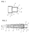
- FIG. 1 shows a cross section of a clamp ring according to an embodiment of the present invention.
- the clamp ring 10 of this embodiment comprises: a first annular portion 11; a second annular portion 12, having a smaller diameter than the first annular portion 11; a step portion 13, connecting the first annular portion 11 and the second annular portion 12 to each other; and a clamping portion 14, which is provided immediately adjacent to the rear end of the second annular portion 12 and extends inward. All these portions are formed as a single piece.
- the inside diameter of an opening 14b, formed by an end face 14a of the clamping portion 14, is made slightly larger than the outside diameter of the earlier mentioned optical fibre cable.
- the outside diameter of the second annular portion 12 is set to fit the diameter rating of a crimping tool to be used in the crimping operation.
- the first annular portion 11 has an inside diameter which fits a rear end portion of a stopper as described earlier. It is constructed so that a tensile strength member is secured between an inside curved surface 11a of the first annular portion 11 and an inside surface 13a of the step portion 13, when the first annular portion 11 is crimped from around its outer periphery.
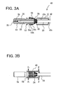
- FIG. 2 shows a general construction diagram of an optical connector which employs the clamp ring of this embodiment.
- a ferrule 31, in which an optical fibre 21 is inserted and fixed has a flange 32.
- the stopper 34a is fitted behind a rear end portion of the ferrule 31, in the back of the flange 32, with a compression spring 33.
- Spring 33 is mounted on the outer periphery of the rear end portion of the ferrule 31.
- a coated optical fibre 22 is inserted into the compression spring 33 and the stopper 34a.
- a tensile strength member 24 of an optical fibre cable 23 is located at the rear end of the stopper 34b. The tensile strength member 24 is secured between the clamp ring 10 and an outer peripheral surface of the rear end portion of the stopper 34b by crimping.
- the inside diameter of the opening 14b, formed by the end face 14a of the clamping portion 14, is slightly larger than the outside diameter of the above-mentioned optical fibre cable.
- the outside diameter of the second annular portion 12 is set to fit the diameter rating of the crimping tool used in the crimping operation.
- the optical fibre cable 23 is clamped by the clamping portion 14 by crimping the second annular portion 12 with the crimping tool.
- the tensile strength member 24 is secured between the inside curved surface 11a of the first annular portion 11 and the stopper 34, and between the inside surface 13a of the step portion 13 and the stopper 34, by crimping the first annular portion.
- the clamp ring 10 of this embodiment provides the advantageous effects that it can be produced extremely easily by press forming, for instance, and its crimping operation can also be performed relatively easily.
- an optical connector may be a resin-molded product in which a flange, a compression spring and a stopper are integrally formed.
- FIG. 3A-3B show an optical fibre terminating structure according to a second embodiment of the present invention.
- a clamp ring 40 used in this embodiment includes a main annular portion 41, which fits on the outer periphery of a rear end portion of a ferrule. Ring 40 also has a clamping portion 42, which extends inward from the rear end of the main annular portion 41 so that its innermost end clamps the outer periphery of an optical fibre cable 23.
- the main annular portion 41 and the clamping portion 42 are formed as a one-piece metallic part having an approximately uniform thickness.
- the inside diameter of an opening 42a formed by the clamping portion 42 is made slightly larger than the outside diameter of the aforementioned optical fibre cable 23.
- the outside diameter of the main annular portion 41 is set to fit the diameter rating of a crimping tool used in the crimping operation. Further, the inside diameter of the main annular portion 41 is made slightly larger than the diameter of the outer periphery 53 of the rear end portion of the ferrule 51.
- the tensile strength member 24 is secured between an inside curved surface 41a of the main annular portion 41 and the outer periphery 53 of the ferrule 51. The parts are joined by crimping both ends of the main annular portion 41 from around its outer periphery.
- the ferrule 51 in which an optical fibre 21 is inserted and fixed, has a flange 52.
- three stepped ridges 54a-54c are integrally formed on the surface of the outer periphery 53.
- the flange 52 may be produced either as a discrete component (of stainless steel, for instance), or as an integral part of the ferrule.
- the following discussion deals with a procedure for making a terminating structure in which the optical fibre cable 23 is connected to the ferrule 51 using the aforementioned clamp ring 40.
- the clamp ring 40 is passed over the optical fibre cable 23.
- An outer covering, or jacket, of the optical fibre cable 23 is removed near its end to expose the coated optical fibre 22, the tensile strength member 24 and the optical fibre 21.
- the optical fibre 21 is inserted into an optical fibre insertion hole 25 of the ferrule 51 while the coated optical fibre 22 is inserted into a core insertion hole 26 of the ferrule 51.
- the optical fibre 21 and the coated optical fibre 22 are secured in position with an adhesive readily filled in the aforementioned optical fibre insertion hole 25 and the core insertion hole 26.
- the tensile strength member 24 of the optical fibre cable 23 is located around the outer periphery 53 of the rear end portion of the ferrule 51, thus being attached at this point. With the tensile strength member 24 disposed between the clamp ring 40 and the outer peripheral surface of the rear end portion of the ferrule 51 at the back of the flange 52; the clamp ring 40 is crimped and fixed by using the crimping tool as shown in FIG. 3(b). Thus, the tensile strength member 24 can be secured in position by crimping the ferrule side of the clamp ring 40.
- the jacket (formed of PVC, for instance) of the optical fibre cable 23 can be secured by crimping the optical fibre cable side of the clamp ring 40.
- the far end of the ferrule 51 is polished together with the optical fibre 21, to complete an optical fibre cable product already fitted with a ferrule.
- the present embodiment provides the advantageous effects that it avoids the conventionally used adhesive, the optical fibre cable 23 and the ferrule 51 can be joined together in an extremely simple and easy way, and the optical fibre cable does not loose its flexibility.
- the number of the stepped ridges 54 is not limited thereto in this invention.
- the outer periphery 53 of the rear end portion of the ferrule 51 may feature small pits and protrusions on its surface (to form a so-called knurled surface) instead of forming the aforementioned stepped ridges.
- the tensile strength member 24 is firmly retained by such small pits and protrusions when the clamp ring is fitted.
- a flange 52 on the ferrule 51 in this embodiment its structure may be varied by employing another type of clamp ring as shown in FIG. 4.
- the outer periphery of the clamp ring 40 and that of a ferrule 51 have the same diameter.
- An outer peripheral part 73 of the rear end portion of the ferrule 71 is made slightly smaller in diameter than the inside curved surface 41a of the clamp ring 40.
- FIG. 5A-5B show an optical fibre terminating structure according to a third embodiment of the invention.
- a clamp ring 60 used in this embodiment comprises: a first annular portion 61; a second annular portion 62, having a smaller diameter than the first annular portion 61; a step portion 63, connecting the first annular portion 61 and the second annular portion 62 to each other; and a clamping portion 64, which is provided immediately adjacent to the rear end of the second annular portion 62 and extends inward. All these potions are formed as a single piece, in a manner similar to the first embodiment shown in FIG. 1.
- the inside diameter of an opening 64b, formed by an end face 64a of the clamping portion 64 is made slightly larger than the outside diameter of the earlier mentioned optical fibre cable.
- the outside diameter of the second annular portion 62 is set to fit the diameter rating of a crimping tool to be used in the crimping operation. Further, the diameter of the first annular portion 61 is made slightly larger than the diameter of the outer periphery 53 of the rear end portion of the ferrule 51. Thus, the tensile strength member 24 is secured between an inside curved surface 61a of the first annular portion 61 and the outer periphery 53 of the ferrule 51. The parts are joined by crimping both ends of the first annular portion 61 from around its outer periphery.
- the optical fibre terminating structure of this embodiment is made by joining the optical fibre cable 23 to the ferrule 51 by using the clamp ring 60 in a manner similar to the second embodiment.
- the clamp ring 60 is passed over the optical fibre cable 23.
- the optical fibre 21 is inserted into the optical fibre insertion hole 25 of the ferrule 51.
- the coated optical fibre 22 is inserted into the core insertion hole 26 of the ferrule 51.
- the optical fibre and the coated optical fibre 22 are secured in position with an adhesive, as shown in FIG. 5A.
- the clamp ring 60 is crimped and fixed by using the crimping tool as shown in FIG. 5B.
- the tensile strength member 24 can be secured between the outer periphery 53 of the rear end portion of the ferrule 51 and the inside curved surface 61a of the first annular portion 61. This is achieved by crimping the first annular portion 61 of the clamp ring 60 from around its outer peripheral surface.
- the tensile strength member 24 can also be secured between the outer periphery 53 of the rear end portion of the ferrule and an inside curved surface 63a of the step portion 63, to provide increased fixing strength. This is achieved by crimping the first annular portion 61 of the clamp ring 60 from around its outer peripheral surface. Furthermore, the jacket (formed of PVC, for instance) of the optical fibre cable 23 can be secured by clamping it by the end face 64a at the clamping portion 64.
- the present embodiment provides advantages, as does the earlier-described embodiment, in that it becomes unnecessary to use the conventionally used adhesive.
- the optical fibre cable 23 and the ferrule 51 can be joined together in an extremely simple and easy way. Further, the optical fibre cable does not loose its flexibility. This embodiment makes it possible to join the optical fibre to the ferrule even more firmly.
- the clamp rings of the present invention are easy to produce and their crimping operation can be performed relatively easily. They are formed to have approximately a uniform thickness throughout their whole structure. The outer periphery of the optical fibre cable is clamped by the end face of the clamping portion which extends inward from the rear end of the second annular portion as described above.
- the optical fibre terminating structures of the present invention provide advantageous effects in that they facilitate the fixing operation due to their construction. That is, the clamp rings have an approximately uniform thickness throughout. The tensile strength member is secured by crimping the clamp ring fitted over the outer periphery of the rear end portion of each ferrule. Further, the number of processes and labour hours required for the fixing operation can be reduced, since the individual components can be fixed together without using an adhesive unlike the conventional structure.
Landscapes
- Physics & Mathematics (AREA)
- General Physics & Mathematics (AREA)
- Optics & Photonics (AREA)
- Mechanical Coupling Of Light Guides (AREA)
Applications Claiming Priority (4)
| Application Number | Priority Date | Filing Date | Title |
|---|---|---|---|
| JP4437197 | 1997-02-27 | ||
| JP44371/97 | 1997-02-27 | ||
| JP241527/97 | 1997-09-05 | ||
| JP9241527A JPH10300983A (ja) | 1997-02-27 | 1997-09-05 | 係止リング及び光ファイバ成端構造 |
Publications (2)
| Publication Number | Publication Date |
|---|---|
| EP0862072A2 true EP0862072A2 (de) | 1998-09-02 |
| EP0862072A3 EP0862072A3 (de) | 1999-01-07 |
Family
ID=26384238
Family Applications (1)
| Application Number | Title | Priority Date | Filing Date |
|---|---|---|---|
| EP98301460A Withdrawn EP0862072A3 (de) | 1997-02-27 | 1998-02-27 | Klemmringe und Struktur zum Abschluss optischer Fasern |
Country Status (5)
| Country | Link |
|---|---|
| US (1) | US6431783B2 (de) |
| EP (1) | EP0862072A3 (de) |
| JP (1) | JPH10300983A (de) |
| CN (1) | CN1195784A (de) |
| TW (1) | TW469354B (de) |
Cited By (9)
| Publication number | Priority date | Publication date | Assignee | Title |
|---|---|---|---|---|
| WO2000073830A1 (fr) * | 1999-06-01 | 2000-12-07 | Nippon Telegraph And Telephone Corporation | Connecteur libre optique, procede de fabrication et outil d'assemblage |
| EP1245980A3 (de) * | 2001-03-28 | 2004-04-28 | Corning Cable Systems LLC | Verteilersatz für Glasfaserkabel |
| WO2005006049A1 (en) * | 2003-07-02 | 2005-01-20 | Adc Telecommunications, Inc. | Furcation device for fiber optical cables with crimp means for strength member |
| WO2005073767A1 (en) * | 2004-01-31 | 2005-08-11 | Tyco Electronics Raychem Nv | A crimp for an optical cable connector |
| US7280725B2 (en) | 2004-06-15 | 2007-10-09 | Adc Telecommunications, Inc. | Fiber optic furcation tube and method |
| EP1949156A4 (de) * | 2005-10-24 | 2011-04-13 | 3M Innovative Properties Co | Optischer verbinder, faserverteilereinheit und faserabschlussplattform für optische verbinder |
| US8118495B2 (en) | 2005-10-28 | 2012-02-21 | 3M Innovative Properties Company | Method of assembling an optical connector and an optical connector |
| US8118494B2 (en) | 2007-02-16 | 2012-02-21 | 3M Innovative Properties Company | Remote grip optical fiber connector |
| EP4043935A4 (de) * | 2019-10-28 | 2022-12-07 | Huawei Technologies Co., Ltd. | Vorverbinder und kommunikationsgerät |
Families Citing this family (22)
| Publication number | Priority date | Publication date | Assignee | Title |
|---|---|---|---|---|
| JP2001215358A (ja) * | 2000-01-31 | 2001-08-10 | Molex Inc | 光ファイバ用フェルール及びその製造方法 |
| US20030091299A1 (en) * | 2001-11-14 | 2003-05-15 | Priest James R. | Crimp-style connector for fiber reinforced premise cable |
| US6764225B2 (en) * | 2002-03-01 | 2004-07-20 | Fci Americas Technology, Inc. | Optic fiber connectors |
| US6893165B2 (en) * | 2002-03-01 | 2005-05-17 | Fci Americas Technology, Inc. | Optic fiber connectors and coupling sleeve |
| JP3938912B2 (ja) * | 2003-07-03 | 2007-06-27 | 日本圧着端子製造株式会社 | 光プラグ付き光ファイバケーブル |
| US6962445B2 (en) | 2003-09-08 | 2005-11-08 | Adc Telecommunications, Inc. | Ruggedized fiber optic connection |
| WO2006100763A1 (ja) * | 2005-03-23 | 2006-09-28 | Honda Tsushin Kogyo Co., Ltd. | 光ケーブルの固定構造 |
| US7572065B2 (en) | 2007-01-24 | 2009-08-11 | Adc Telecommunications, Inc. | Hardened fiber optic connector |
| US7591595B2 (en) * | 2007-01-24 | 2009-09-22 | Adc Telelcommunications, Inc. | Hardened fiber optic adapter |
| US7744286B2 (en) | 2007-12-11 | 2010-06-29 | Adc Telecommunications, Inc. | Hardened fiber optic connection system with multiple configurations |
| DE202010005766U1 (de) * | 2009-06-16 | 2010-10-28 | Weidmüller Interface GmbH & Co. KG | Werkzeug zur Verarbeitung von Lichtwellenleitern |
| JP5599237B2 (ja) * | 2010-06-23 | 2014-10-01 | 矢崎総業株式会社 | 光コネクタ |
| US8221006B2 (en) | 2010-08-23 | 2012-07-17 | Corning Cable Systems Llc | Fiber optic cable assemblies with mechanically interlocking crimp bands and methods of making the assemblies |
| JP2012220799A (ja) * | 2011-04-11 | 2012-11-12 | Furukawa Electric Co Ltd:The | 光ファイバ端子、端子付光ファイバケーブル、光コネクタ、およびコネクタ付光ファイバケーブル |
| JP2012220798A (ja) * | 2011-04-11 | 2012-11-12 | Furukawa Electric Co Ltd:The | 光ファイバ端子、端子付光ファイバケーブル、光コネクタ、およびコネクタ付光ファイバケーブル |
| JP5737245B2 (ja) * | 2011-12-28 | 2015-06-17 | 住友電気工業株式会社 | 光ケーブル端末固定具、光ケーブルの端末固定構造及び光モジュール |
| TWI484233B (zh) * | 2012-12-21 | 2015-05-11 | Foci Fiber Optic Communications Inc | 光纖接頭之抗張體固定結構 |
| US10444443B2 (en) | 2013-06-27 | 2019-10-15 | CommScope Connectivity Belgium BVBA | Fiber optic cable anchoring device for use with fiber optic connectors and methods of using the same |
| WO2015034961A1 (en) * | 2013-09-06 | 2015-03-12 | Adc Telecommunications, Inc. | Optical fiber connector and cable assembly with dual diameter crimp sleeve |
| US9921373B2 (en) * | 2013-12-19 | 2018-03-20 | Exfo Inc. | Fiber-optic connector mating assembly for optical test instruments |
| EP3224661B1 (de) | 2014-11-26 | 2020-03-25 | Corning Optical Communications LLC | Faseroptische verbinder und baugruppen mit stützelementfixierung |
| CN114660728B (zh) * | 2022-03-23 | 2023-11-14 | 中航光电科技股份有限公司 | 一种光纤接触件及光纤连接器 |
Family Cites Families (18)
| Publication number | Priority date | Publication date | Assignee | Title |
|---|---|---|---|---|
| US3227993A (en) * | 1960-10-24 | 1966-01-04 | Microdot Inc | Electrical connector |
| DE2236248C2 (de) * | 1972-07-24 | 1982-12-09 | Felten & Guilleaume Energietechnik GmbH, 5000 Köln | Verfahren zur Herstellung einer Kunststoffkabelgarnitur |
| GB1526397A (en) * | 1974-10-08 | 1978-09-27 | Raychem Ltd | Heat-recoverable article suitable for high voltage use |
| US4026628A (en) * | 1975-04-21 | 1977-05-31 | Grumman Aerospace Corporation | Electrical connector for cables and magnetic forming process for same |
| US4070751A (en) * | 1977-01-12 | 1978-01-31 | Amp Incorporated | Method of making a coaxial connector |
| AU5349279A (en) * | 1978-12-18 | 1980-06-26 | Amerace Corporation | Splice connector housing |
| US4447121A (en) * | 1981-11-06 | 1984-05-08 | Amp Incorporated | Connector for fiber optic member |
| JPS60170808A (ja) * | 1984-02-15 | 1985-09-04 | Nec Corp | 簡易形光コネクタ |
| US4679895A (en) * | 1984-08-31 | 1987-07-14 | Amp Incorporated | Adhesiveless optical fiber connector |
| US5181267A (en) * | 1988-02-23 | 1993-01-19 | Amp Incorporated | Sheath connector for an optical cable |
| GB2229829B (en) * | 1989-03-31 | 1993-03-17 | Philips Nv | A connector for a fibre optic cable |
| US5073044A (en) * | 1990-10-31 | 1991-12-17 | Amp Incorporated | Right angle strain relief for optical fiber connector |
| US5101463A (en) * | 1991-05-03 | 1992-03-31 | Minnesota Mining And Manufacturing Company | Push-pull optical fiber connector |
| US5222169A (en) * | 1992-02-18 | 1993-06-22 | Foxconn International, Inc. | Optical fiber connector assembly |
| US5363459A (en) * | 1993-01-15 | 1994-11-08 | The Whitaker Corporation | Optical fiber connector including a biasing means in housing |
| US5390272A (en) * | 1993-08-31 | 1995-02-14 | Amphenol Corporation | Fiber optic cable connector with strain relief boot |
| US5418874A (en) * | 1994-01-19 | 1995-05-23 | At&T Corp. | Force transfer system for an optical fiber connector |
| US5682451A (en) * | 1995-05-23 | 1997-10-28 | Minnesota Mining And Manufacturing Company | Device with internal features for rotational alignment of non-cylindrically symmetrical optical elements |
-
1997
- 1997-09-05 JP JP9241527A patent/JPH10300983A/ja active Pending
-
1998
- 1998-02-24 TW TW087102652A patent/TW469354B/zh not_active IP Right Cessation
- 1998-02-26 US US09/031,482 patent/US6431783B2/en not_active Expired - Fee Related
- 1998-02-27 EP EP98301460A patent/EP0862072A3/de not_active Withdrawn
- 1998-02-27 CN CN98107735A patent/CN1195784A/zh active Pending
Cited By (16)
| Publication number | Priority date | Publication date | Assignee | Title |
|---|---|---|---|---|
| US6913394B2 (en) | 1999-06-01 | 2005-07-05 | Nippon Telegraph And Telephone Corporation | Optical connector plug, manufacturing method thereof and assembling tool |
| KR100713430B1 (ko) * | 1999-06-01 | 2007-05-04 | 니폰덴신뎅와 가부시키가이샤 | 광커넥터 플러그, 그 제조방법 및 조립공구 |
| WO2000073830A1 (fr) * | 1999-06-01 | 2000-12-07 | Nippon Telegraph And Telephone Corporation | Connecteur libre optique, procede de fabrication et outil d'assemblage |
| EP1245980A3 (de) * | 2001-03-28 | 2004-04-28 | Corning Cable Systems LLC | Verteilersatz für Glasfaserkabel |
| WO2005006049A1 (en) * | 2003-07-02 | 2005-01-20 | Adc Telecommunications, Inc. | Furcation device for fiber optical cables with crimp means for strength member |
| US6909828B2 (en) | 2003-07-02 | 2005-06-21 | Adc Telecommunications, Inc. | Fiberoptic furcation device with crimp |
| US7035510B2 (en) | 2003-07-02 | 2006-04-25 | Adc Telecommunications, Inc. | Fiberoptic furcation device with crimp |
| US9188749B2 (en) | 2004-01-31 | 2015-11-17 | Tyco Electronics Raychem Bvba | Crimp for an optical cable connector |
| WO2005073767A1 (en) * | 2004-01-31 | 2005-08-11 | Tyco Electronics Raychem Nv | A crimp for an optical cable connector |
| AU2005208077B2 (en) * | 2004-01-31 | 2008-09-11 | CommScope Connectivity Belgium BV | A crimp for an optical cable connector |
| US9851513B2 (en) | 2004-01-31 | 2017-12-26 | CommScope Connectivity Belgium BVBA | Crimp for an optical cable connector |
| US7280725B2 (en) | 2004-06-15 | 2007-10-09 | Adc Telecommunications, Inc. | Fiber optic furcation tube and method |
| EP1949156A4 (de) * | 2005-10-24 | 2011-04-13 | 3M Innovative Properties Co | Optischer verbinder, faserverteilereinheit und faserabschlussplattform für optische verbinder |
| US8118495B2 (en) | 2005-10-28 | 2012-02-21 | 3M Innovative Properties Company | Method of assembling an optical connector and an optical connector |
| US8118494B2 (en) | 2007-02-16 | 2012-02-21 | 3M Innovative Properties Company | Remote grip optical fiber connector |
| EP4043935A4 (de) * | 2019-10-28 | 2022-12-07 | Huawei Technologies Co., Ltd. | Vorverbinder und kommunikationsgerät |
Also Published As
| Publication number | Publication date |
|---|---|
| JPH10300983A (ja) | 1998-11-13 |
| US20010038770A1 (en) | 2001-11-08 |
| EP0862072A3 (de) | 1999-01-07 |
| CN1195784A (zh) | 1998-10-14 |
| US6431783B2 (en) | 2002-08-13 |
| TW469354B (en) | 2001-12-21 |
Similar Documents
| Publication | Publication Date | Title |
|---|---|---|
| EP0862072A2 (de) | Klemmringe und Struktur zum Abschluss optischer Fasern | |
| US5202942A (en) | Cable termination member for fiber optic connectors having improved strain relief | |
| US5806175A (en) | Crimp assembly for connecting an optical fiber ribbon cord to a connector | |
| EP1245980B1 (de) | Verteilersatz für Glasfaserkabel | |
| US4336977A (en) | Crimped connector assembly for fiber optic cables | |
| US9625660B2 (en) | Cable termination assembly and method for connectors | |
| US4447120A (en) | Fiber optic cable clamp | |
| EP2283390B1 (de) | Gehärteter faseroptischer verbinder mit einem verbinderkörper, der durch ein unitäres gehäuse mit einem zylindrischen kabel verbunden wird | |
| TW513585B (en) | Fiber optic connector | |
| EP0664467A1 (de) | Zugentrastung für einen faseroptischen Stecker | |
| EP0638828A1 (de) | Optischer Stecker mit einer einteiligen Kappe | |
| US20020164130A1 (en) | Fiber optic module attachment including a fiber locating connector | |
| US5140662A (en) | Method of assembling connector and cable | |
| US4961624A (en) | Optical fiber termination with crimping body | |
| US6340249B1 (en) | Connector assembly and method of securing fiber optic cable to connector | |
| JPH11352368A (ja) | 多心光ファイバテープの多心単心変換部 | |
| JPH0331923Y2 (de) | ||
| US6272273B1 (en) | Hermetic cable joint | |
| US6196731B1 (en) | Quick-connect fiber optic connector | |
| US6997620B2 (en) | Optical plug and mounting method thereof | |
| US7431515B1 (en) | Fiber optic termini having multiple crimp portions and method of using same | |
| EP0024959A1 (de) | Verbindung für optische Wellenleiter | |
| US20200241217A1 (en) | Retention apparatus and method for terminating a jacketed cable | |
| GB2031605A (en) | Crimped connector assembly for fiber optic cables or the like | |
| JPS6128172Y2 (de) |
Legal Events
| Date | Code | Title | Description |
|---|---|---|---|
| PUAI | Public reference made under article 153(3) epc to a published international application that has entered the european phase |
Free format text: ORIGINAL CODE: 0009012 |
|
| AK | Designated contracting states |
Kind code of ref document: A2 Designated state(s): DE FR GB IT |
|
| AX | Request for extension of the european patent |
Free format text: AL;LT;LV;MK;RO;SI |
|
| PUAL | Search report despatched |
Free format text: ORIGINAL CODE: 0009013 |
|
| AK | Designated contracting states |
Kind code of ref document: A3 Designated state(s): AT BE CH DE DK ES FI FR GB GR IE IT LI LU MC NL PT SE |
|
| AX | Request for extension of the european patent |
Free format text: AL;LT;LV;MK;RO;SI |
|
| 17P | Request for examination filed |
Effective date: 19990707 |
|
| AKX | Designation fees paid |
Free format text: DE FR GB IT |
|
| 17Q | First examination report despatched |
Effective date: 19990810 |
|
| STAA | Information on the status of an ep patent application or granted ep patent |
Free format text: STATUS: THE APPLICATION IS DEEMED TO BE WITHDRAWN |
|
| 18D | Application deemed to be withdrawn |
Effective date: 20031111 |