EP0862278A2 - Unité de communication et procédé de connection de l'antenne - Google Patents
Unité de communication et procédé de connection de l'antenne Download PDFInfo
- Publication number
- EP0862278A2 EP0862278A2 EP98660007A EP98660007A EP0862278A2 EP 0862278 A2 EP0862278 A2 EP 0862278A2 EP 98660007 A EP98660007 A EP 98660007A EP 98660007 A EP98660007 A EP 98660007A EP 0862278 A2 EP0862278 A2 EP 0862278A2
- Authority
- EP
- European Patent Office
- Prior art keywords
- antenna
- contact pin
- communication unit
- module
- contact
- Prior art date
- Legal status (The legal status is an assumption and is not a legal conclusion. Google has not performed a legal analysis and makes no representation as to the accuracy of the status listed.)
- Withdrawn
Links
- 238000004891 communication Methods 0.000 title claims abstract description 29
- 238000000034 method Methods 0.000 title claims description 5
- 239000004020 conductor Substances 0.000 description 12
- 238000009434 installation Methods 0.000 description 11
- 230000008878 coupling Effects 0.000 description 5
- 238000010168 coupling process Methods 0.000 description 5
- 238000005859 coupling reaction Methods 0.000 description 5
- 230000005855 radiation Effects 0.000 description 3
- 230000005540 biological transmission Effects 0.000 description 2
- 238000004519 manufacturing process Methods 0.000 description 2
- 238000000053 physical method Methods 0.000 description 2
- 229910000679 solder Inorganic materials 0.000 description 2
- 238000005452 bending Methods 0.000 description 1
- 238000010276 construction Methods 0.000 description 1
- 230000006866 deterioration Effects 0.000 description 1
- 239000012212 insulator Substances 0.000 description 1
- 230000010354 integration Effects 0.000 description 1
- 238000005259 measurement Methods 0.000 description 1
- 230000001681 protective effect Effects 0.000 description 1
- 238000004904 shortening Methods 0.000 description 1
- 229920002379 silicone rubber Polymers 0.000 description 1
- 238000005303 weighing Methods 0.000 description 1
Images




Classifications
-
- H—ELECTRICITY
- H04—ELECTRIC COMMUNICATION TECHNIQUE
- H04M—TELEPHONIC COMMUNICATION
- H04M1/00—Substation equipment, e.g. for use by subscribers
- H04M1/02—Constructional features of telephone sets
- H04M1/0202—Portable telephone sets, e.g. cordless phones, mobile phones or bar type handsets
- H04M1/0254—Portable telephone sets, e.g. cordless phones, mobile phones or bar type handsets comprising one or a plurality of mechanically detachable modules
-
- H—ELECTRICITY
- H01—ELECTRIC ELEMENTS
- H01Q—ANTENNAS, i.e. RADIO AERIALS
- H01Q1/00—Details of, or arrangements associated with, antennas
- H01Q1/12—Supports; Mounting means
- H01Q1/22—Supports; Mounting means by structural association with other equipment or articles
- H01Q1/2258—Supports; Mounting means by structural association with other equipment or articles used with computer equipment
- H01Q1/2275—Supports; Mounting means by structural association with other equipment or articles used with computer equipment associated to expansion card or bus, e.g. in PCMCIA, PC cards, Wireless USB
-
- H—ELECTRICITY
- H01—ELECTRIC ELEMENTS
- H01Q—ANTENNAS, i.e. RADIO AERIALS
- H01Q1/00—Details of, or arrangements associated with, antennas
- H01Q1/12—Supports; Mounting means
- H01Q1/22—Supports; Mounting means by structural association with other equipment or articles
- H01Q1/24—Supports; Mounting means by structural association with other equipment or articles with receiving set
- H01Q1/241—Supports; Mounting means by structural association with other equipment or articles with receiving set used in mobile communications, e.g. GSM
- H01Q1/242—Supports; Mounting means by structural association with other equipment or articles with receiving set used in mobile communications, e.g. GSM specially adapted for hand-held use
- H01Q1/243—Supports; Mounting means by structural association with other equipment or articles with receiving set used in mobile communications, e.g. GSM specially adapted for hand-held use with built-in antennas
-
- H—ELECTRICITY
- H01—ELECTRIC ELEMENTS
- H01Q—ANTENNAS, i.e. RADIO AERIALS
- H01Q1/00—Details of, or arrangements associated with, antennas
- H01Q1/12—Supports; Mounting means
- H01Q1/22—Supports; Mounting means by structural association with other equipment or articles
- H01Q1/24—Supports; Mounting means by structural association with other equipment or articles with receiving set
- H01Q1/241—Supports; Mounting means by structural association with other equipment or articles with receiving set used in mobile communications, e.g. GSM
- H01Q1/242—Supports; Mounting means by structural association with other equipment or articles with receiving set used in mobile communications, e.g. GSM specially adapted for hand-held use
- H01Q1/243—Supports; Mounting means by structural association with other equipment or articles with receiving set used in mobile communications, e.g. GSM specially adapted for hand-held use with built-in antennas
- H01Q1/244—Supports; Mounting means by structural association with other equipment or articles with receiving set used in mobile communications, e.g. GSM specially adapted for hand-held use with built-in antennas extendable from a housing along a given path
-
- H—ELECTRICITY
- H04—ELECTRIC COMMUNICATION TECHNIQUE
- H04B—TRANSMISSION
- H04B1/00—Details of transmission systems, not covered by a single one of groups H04B3/00 - H04B13/00; Details of transmission systems not characterised by the medium used for transmission
- H04B1/38—Transceivers, i.e. devices in which transmitter and receiver form a structural unit and in which at least one part is used for functions of transmitting and receiving
- H04B1/3816—Mechanical arrangements for accommodating identification devices, e.g. cards or chips; with connectors for programming identification devices
-
- H—ELECTRICITY
- H04—ELECTRIC COMMUNICATION TECHNIQUE
- H04B—TRANSMISSION
- H04B1/00—Details of transmission systems, not covered by a single one of groups H04B3/00 - H04B13/00; Details of transmission systems not characterised by the medium used for transmission
- H04B1/38—Transceivers, i.e. devices in which transmitter and receiver form a structural unit and in which at least one part is used for functions of transmitting and receiving
- H04B1/3827—Portable transceivers
- H04B1/3833—Hand-held transceivers
Definitions
- the present invention relates to a communication unit and antennae used in connection with it.
- the invention relates to an antenna connection used in connection with a radio module implemented within a PCMCIA data card. Both a separate external antenna and a fixed antenna can be coupled to the antenna connection according to the present invention.
- the transferable mobile phones When the first transferable mobile phones, weighing several kilograms each, entered into the market, they had two basic uses.
- the transferable mobile phones were used either fixed to the vehicle and normally equipped with an extemal vehicle antenna attached to the vehicle's roof or they were used outside the vehicle by means of a so-called whip antenna attached to the mobile phone.
- the antenna connection was implemented by means of a coaxial connector often by using a BNC or Baby "N" Connector, known to persons skilled in the art.
- Coaxial connections to mobile phone antennae are described e.g. in patent publications EP 407 145, WO 96/27916 and US 5 551 080.
- a fixed whip antenna is used in portable mobile phones.
- a mobile phone is attached, e.g., to a vehicle, this is done through a separate installation mount.
- the fixed antenna switches off and an external vehicle antenna switches on, typically, by means of a separate antenna connector, installed on the mobile phone's bottom, and a counterpart, fixed to the installation mount, as shown in Figure 2.
- An antenna selector is responsible for switching between the antennas. This system operates well in practice, because the mobile phone can be easily detached from and attached to the installation mount, and the antenna is selected automatically.
- the system's drawbacks are a connection loss in the antenna selector, as well as the use of a small coaxial connector the manufacturing costs of which are high, in connection with an external antenna.
- high manufacturing accuracy is required of the installation mount, because the small coaxial connector should go exactly in the right place, when the mobile phone is attached to its installation mount.
- the small coaxial connectors are sensitive to dirt, wearing and they are also easily broken.
- the solution also presupposes additional components, such as an antenna selector. Figure 2 will be described later in more detail.
- Radio modules or mobile stations coupled to portable computers, by means of which a portable computer can be connected to telecommunications networks wirelessly using radio communication, are becoming an important application.
- a radio module is coupled to a portable computer through a data bus, e.g., a PCMCIA (Personal Computer Memory Card International Association) bus, which is currently the most commonly used bus. It is possible to install, in the PCMCIA bus, a PCMCIA card about the size of a credit card, whereon the electronic components required by the radio module can be installed.
- PCMCIA Personal Computer Memory Card International Association
- the PCMCIA card's small physical measurements set strict limits to the components to be used in connection with the PCMCIA card.
- the implementation of an antenna has proved extremely problematic, because it has been impossible to implement a small and reliable antenna connection.
- solutions based, e.g., on small coaxial connectors are expensive to implement due to the accuracy required of the fine-mechanical parts and they also break easily.
- the centre pin of a small coaxial connector remains thin and weak. Therefore, this type of connector is not suitable for use in very small radio modules, e.g., the size of a data card, wherein the antenna must often be turned from one position to another.
- a thin and weak centre pin wears and does not guarantee reliable contact for an antenna signal.
- Patent Publication EP 0 610 025 A1 a solution has been presented, wherein a PCMCIA card modem has been implemented, the card modem consisting of two or more modules, substantially the size of a PCMCIA card, which have been articulated with one another.
- the antenna used has been integrated on the surface of a circuit board within a module located outside a computer.
- the solution used requires a complex mechanical structure between the different modules and is unsuitable for small radio modules the size of only one PCMCIA card.
- the implementation of an antenna within the same module on the same circuit board as the rest of the electronics causes a problem in the form of radio interference and the deterioration of the antenna's radiation properties.
- an arrangement according to said publication does not enable a separate extemal antenna to be coupled in connection with a data card.
- the contacts are not made in a coaxial manner, but by two opposed contact pins, whereby an antenna signal is transmitted between a radio module and an antenna using a first contact pin and the radio module's ground potential required in connection with an extemal antenna, in particular, is transmitted to the extemal antenna using a second contact pin, where the second contact pin is at a distance from the first contact pin so that the first and second contact pins form two opposed contact pins.
- an antenna module resembling a fixed antenna, e.g., to a PCMCIA data card by means of a durable and small antenna connection consisting of two separate connections, which, when turned in the direction of the card, integrates as part of the PCMCIA card.
- the antenna module When the antenna module is turned to an upright position, the antenna module will produce an even better radiation pattern than before.
- the antenna module can be replaced with an external antenna.
- the external antenna is preferably installed, by means of a cable, in the same antenna connection as the antenna module mentioned above.
- the centre conductor of the antenna cable coming from the external antenna is coupled to the same first connection as the antenna module, but the ground conductor required in connection with the external antenna (e.g., a coaxial cable shield) is coupled to a separate ground connector (a second connector) according to the present invention.
- a separate ground connector e.g., a coaxial cable shield
- the size of the connector used for the extemal antenna's centre conductor is only restricted by the physical measurements of the data card. Because it is not preferably necessary to use a coaxial connector type, it is possible to implement, by means of the present invention, a durable antenna connection having a large area and providing a good contact, in a small space.
- a communication unit comprising a radio module, antenna connecting means for connecting an antenna to said radio module, said antenna connecting means comprising a first contact pin for transmitting an antenna signal between said radio and said antenna, the communication unit being characterised in that said antenna connecting means comprise a second contact pin for providing a ground potential of the radio module to said antenna, said second contact pin is at a distance from said first contact pin so that the first and second contact pin form two opposed contact pins.
- an antenna comprising antenna connecting means for connecting the antenna to a transceiver unit, said antenna connecting means comprising a first contact pin for connecting an antenna signal between the antenna and said transceiver unit, the antenna being characterised in that said antenna connecting means comprise a second contact pin for providing a ground potential of said transceiver unit to said antenna, said second contact pin is at a distance from said first contact pin so that the first and second contact pin form two opposed contact pins.
- a method for connecting an antenna to a communication unit wherein an antenna signal is connected between said antenna and said communication unit using a first contact pin, the method being characterised in that, in addition, a ground potential of the communication unit is provided to said antenna using a second contact pin, and placing said second contact pin at a distance from said first contact pin so that the first and second contact pin form two opposed contact pins.
- FIG. 1A shows an exemplary system according to prior art for coupling an external antenna 11 to a transferable mobile phone 10. It has been implemented by means of a coaxial cable 13 and a coaxial BNC connector 12.
- An antenna signal 13A is transmitted to the external antenna 11 (indicated by a dashed line) using the coaxial cable 13 and the centre conductor of the BNC connector 12.
- the antenna signal is transmitted, e.g., from a duplex filter 14, but the duplex filter 14 can also be replaced, e.g., with an electric switch.
- a shield 13B of the antenna cable 13 is typically grounded to the frame of the mobile phone 10 having a specific ground potential 17.
- Certain external antennas 11 also presuppose the transmission of the mobile phone's ground potential 17 to the extemal antenna 11.
- the ground potential 17, required by the external antenna 11 or the shield 13B of the antenna cable 13, is coupled using the electric contact provided by the outer circumference of the coaxial BNC 12.
- FIG. 1B shows an arrangement wherein, instead of the external antenna 11, a fixed whip antenna 16 has been installed in the same transferable mobile phone 10.
- the antenna has been fixed by means of an insulated BNC 15.
- the antenna signal 13A is transmitted along the centre conductor of the BNC 15 from the duplex filter 14 to the whip antenna 16, whereas there is no need to establish the separate ground potential 17 from the mobile phone 10 to the whip antenna 16.
- the frame of the mobile phone 10 acts as the ground potential against which the whip antenna 16 radiates.
- the insulated BNC 15 and the fixing mechanism of its external circumference have only been used for mechanically fixing the whip antenna 16.
- FIG 2 shows a well-known arrangement, wherein a portable mobile phone 20 has been fixed to an installation rack 21.
- the mobile phone 20 observes being fixed to the installation rack 21, e.g., by means of a connection strip 22, whereupon an antenna switch 23 switches off a fixed antenna 24 of the mobile phone 20.
- the antenna switch 23 switches an antenna signal 28A (indicated by a dashed line) from a duplex filter 25 to an external antenna 26 in the centre conductor of coaxial cables 27 and 28.
- a small coaxial connector 29A, fixed to the mobile phone, and a coaxial connector 29B, fixed to the installation rack, are used as connectors.
- a ground contact from the mobile phone 20 for the external antenna 26 is produced as described in connection with the legend of Figure 1A using a shield 28B of the coaxial cable 28.
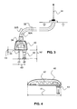
- FIG. 3 shows the implementation of an antenna connection and the electric coupling of antenna signals 32A and 32B according to the present invention using an external antenna 31.
- the antenna conductor 32A centre conductor of coaxial cable
- the antenna plug 33 of an antenna connector 30 has been coupled to an antenna plug 33 of an antenna connector 30.
- the dimensions of the connector 30 and the contact pins may be for example the following: diameter d1 of the ground plug 35 is 1.2 mm, height h1 of the ground plug 35 is 3.3 mm, diameter d2 of the antenna plug 33 is 6.0 mm, height h2 of the antenna plug 33 is 12.1 mm, and the distance d3 between the centres of the ground plug 35 and the antenna plug 33 is 8.0 mm.
- the dimensions of the ground plug 35 and the antenna plug 33 as well as the distance between them easily affects the quality of the rf signal transmitted via the connector and these factors might cause disturbances in the signal.
- disturbances in the radio signal can be reduced by shortening the distance d3 to for example 5.0 mm or 6.0 mm.
- the antenna connector 30 is not able to turn when it has been installed in a data card 50 ( Figure 5). Thus, the antenna connector 30 stays firmly in place and provides a reliable contact for both the antenna signal 32A and the ground contact 32B from the data card 50 to the extemal antenna 31.
- An antenna connection utilising the two separate plugs 33 and 35, according to the present invention, further enables an antenna module 40 (shown in Figure 4) which can be tumed in relation to the data card 50, to be coupled to the same antenna connection.
- the antenna module 40 can be implemented in many different ways.
- Figure 4 shows one preferred implementation of the antenna module 40. It is approximately 54 millimetres long (Reference 41), i.e., having substantially the same width as the PCMCIA data card 50 (Figure 5).
- This provides for an easy installation of the antenna module 40 in connection with the PCMCIA card 50.
- the installation is carried out by means of an antenna plug 43 corresponding to the antenna plug 33 shown in Figure 3.
- the antenna module 40 does not require a separate ground contact and, therefore, there is no need for a connection plug like the ground plug 35 shown in Figure 3.
- the length of the antenna module 40 can be implemented in such a small space, e.g., by implementing a radiating antenna conductor 42 having a helix construction (spiral in shape).
- FIG. 5 shows the PCMCIA card 50 according to the present invention, the card being equipped with an antenna connection according to the invention.
- a base plate 58 containing the electric components of the PCMCIA card 50, is shown in Figure 5 as a separate item.
- the antenna connection of the PCMCIA card 50 consists of a separate antenna socket 51 and a separate ground socket 52.
- the antenna module 40 is coupled to the PCMCIA card according to the present invention by installing the antenna plug 43 of the antenna module 40 in the antenna socket 51 (the first contact pin).
- An electric contact from the antenna plug 43 to the base plate 58 of the PCMCIA data card 50 and further to radio components (not shown in the figure) is implemented by means of an antenna contact 55.
- this antenna contact 55 can made very small (almost flat) by just having a flat plate with e.g. four feet for connecting to the PCB (at four solder points) and where one foot is longer extending and bending upward after the solder point with the PCB to make a spring contact for connecting with the antenna plug 33, 43. Because there is only one fixing point between the antenna 40 and the card 50, the antenna 40 can be tumed to different positions in relation to the PCMCIA card 50. Typically, it is turned to an upright position when the radio module is used in order to achieve a higher quality radio connection. If the PCMCIA card 50 is not in use or it has been detached from the computer, the antenna module 40 can preferably be tumed in the direction of the PCMCIA card.
- the antenna module 40 takes a minimum of space and it is easy to carry the PCMCIA card, e.g., in the pocket.
- the PCMCIA card 50 can be equipped with a protrusion 53 and the antenna module 40 with a slot 54 by means of which the antenna module 40 can be locked so as to better stay in the direction of the top of the PCMCIA card 50.
- the PCMCIA data card 50 is used to establish radio communication in good field conditions, it is not necessary even to turn the radio module 40 to an upright position but, instead, it can be turned in the direction of the PCMCIA card 50.
- the antenna module 40 is detached from the antenna socket 51 (the first contact pin).
- the antenna connector 30, shown in Figure 3 is coupled in its place, the antenna connector comprising both the antenna plug 33 (the first contact pin) and the separate ground plug 35 (the second contact pin) according to the invention.
- the antenna plug 33 is coupled to the antenna socket 51 (the first contact pin) and the ground plug 35 to the ground socket 52 (the second contact pin), correspondingly.
- a contact pin can be in the form of a plug or socket, i.e. male contact or a female contact.
- An electric contact from the antenna plug 33 to the radio components, located on the PCMCIA card base plate 58, is established by means of a method known in connection with the antenna module 40, i.e., by using the antenna contact 55. Instead, now the ground potential of the PCMCIA card 50 is also coupled, as shown in Figure 3, to the shield 32B of the coaxial cable 32. Electric coupling is implemented through the ground plug 35 and the ground contact 56 in a manner characteristic of the invention.
- FIG. 6 shows another implementation of the antenna module 40. It can be coupled to the PCMCIA card 50 by means of an antenna plug 61 similar to the antenna plugs 33 and 43.
- an insulating O ring 62 remains between the antenna plug 61 and the antenna socket 51. It has been made, e.g., of silicon rubber.
- the O ring 62 functions as an insulator and it also prevents dirt from collecting on the contact surfaces of the antenna plug 61 and the antenna socket 51.
- a cover 63 protects both a contact connection 64 and an extension 65, on which a helix element 75 rests, when the antenna is in a retracted position.
- the top layer of the helix element 75 has a protective element 72.
- an antenna signal is transmitted from a spring-like helix element 68 that functions as an antenna through a contact surface 67 and a control unit 66 to the extension 65 and further to the PCMCIA card 50.
- the helix element 75 When the helix element 75 is withdrawn, it slides for a few centimetres, e.g., three to five centimetres, supported by a conductor element 69. When sliding, the helix element 75 and the conductor element are insulated from one another by an insulating bushing 70. When the helix element 75 has been fully withdrawn, the helix element 68, which functions as an antenna, is coupled through a contact surface 71 to the conductor element 69 to produce a longer antenna with excellent radiation properties.
- This telescopic-helix-antenna (antenna module 60) can be installed, like the antenna module 40, crosswise at the top of the PCMCIA card 50 (when retracted, its length is substantially 54 mm), wherefrom it can be tumed to an upright position and drawn long.
- the system according to the present invention is also simple and, thus, economical to implement particularly in connection with PCMCIA modules that utilise radio communication and are manufactured in large series.
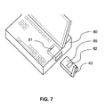
- One of the most important applications relates to the system shown in Figure 7, wherein the functions of a mobile station have been implemented in connection with a portable computer 80 using a PCMCIA mobile station module 85 comprising radio transmission and reception means 82 according to the present invention.
- the mobile station module 85 is equipped with the antenna module 40, shown in Figure 4.
- the mobile station module 85 is installed in a PCMCIA bus 81 of the computer 80.
Landscapes
- Engineering & Computer Science (AREA)
- Computer Networks & Wireless Communication (AREA)
- Signal Processing (AREA)
- Computer Hardware Design (AREA)
- General Engineering & Computer Science (AREA)
- Coupling Device And Connection With Printed Circuit (AREA)
- Transceivers (AREA)
Applications Claiming Priority (2)
| Application Number | Priority Date | Filing Date | Title |
|---|---|---|---|
| FI970618 | 1997-02-14 | ||
| FI970618A FI102927B1 (fi) | 1997-02-14 | 1997-02-14 | Kommunikointiyksikkö, antenni ja menetelmä antennin liittämiseksi |
Publications (1)
| Publication Number | Publication Date |
|---|---|
| EP0862278A2 true EP0862278A2 (fr) | 1998-09-02 |
Family
ID=8548200
Family Applications (1)
| Application Number | Title | Priority Date | Filing Date |
|---|---|---|---|
| EP98660007A Withdrawn EP0862278A2 (fr) | 1997-02-14 | 1998-01-30 | Unité de communication et procédé de connection de l'antenne |
Country Status (3)
| Country | Link |
|---|---|
| US (1) | US6133884A (fr) |
| EP (1) | EP0862278A2 (fr) |
| FI (1) | FI102927B1 (fr) |
Cited By (9)
| Publication number | Priority date | Publication date | Assignee | Title |
|---|---|---|---|---|
| WO2000028672A1 (fr) * | 1998-11-06 | 2000-05-18 | Sierra Wireless, Inc. | Logement de batterie pour modem a carte pcmcia avec antenne |
| WO2001024310A1 (fr) * | 1999-09-27 | 2001-04-05 | Allgon Ab | Dispositif d'antenne pouvant etre connecte a un connecteur homologue |
| GB2361359A (en) * | 2000-04-14 | 2001-10-17 | Matsushita Comm Ind Uk Ltd | Snap-fit antenna for portable communication devices |
| EP1076376A3 (fr) * | 1999-08-12 | 2002-11-20 | Kathrein-Werke KG | Appareil d' extension en forme d' embase d' antenne pour un appareil de réception, en particulier un appareil de réception des signaux vidéo numériques télédiffusés transmis à partir de stations terrestres (DVB-T) |
| EP1174945A3 (fr) * | 2000-07-18 | 2004-01-02 | Option International | Carte de télécommunication avec une antenne intégrée |
| EP1107351A3 (fr) * | 1999-11-30 | 2004-01-07 | Nokia Corporation | Méthode et agencement d'antenne pour coupler des antennes externes à un dispositif de communication |
| EP1278155A3 (fr) * | 2001-07-19 | 2004-01-21 | Matsushita Electric Industrial Co., Ltd. | Dispositif à carte avec une antenne et connecté à un appareil electronique ou à un dispositif sans fil |
| WO2005031910A3 (fr) * | 2003-09-29 | 2005-05-26 | Nokia Corp | Dispositif d'extension |
| CN107275754A (zh) * | 2017-05-25 | 2017-10-20 | 奇酷互联网络科技(深圳)有限公司 | 天线结构、线缆接头和移动终端 |
Families Citing this family (17)
| Publication number | Priority date | Publication date | Assignee | Title |
|---|---|---|---|---|
| JP2000059478A (ja) * | 1998-08-07 | 2000-02-25 | Matsushita Electric Ind Co Ltd | 携帯電話機 |
| US6522299B2 (en) * | 1999-04-08 | 2003-02-18 | Cypress Semiconductor Corp. | PC card retractable antenna |
| JP4053704B2 (ja) * | 2000-01-05 | 2008-02-27 | 株式会社東芝 | 無線インタフェース機能内蔵icカード、アンテナモジュール、情報処理装置 |
| US6847830B1 (en) * | 2000-03-24 | 2005-01-25 | Sierra Wireless, Inc | Retractable antenna for personal computer card |
| FI114592B (fi) | 2000-06-30 | 2004-11-15 | Nokia Corp | Kytkin- ja liitinjärjestely ulkoisten ja sisäisten antennien kytkemiseksi esimerkiksi laajennuskorttiin |
| KR100436665B1 (ko) * | 2001-11-27 | 2004-06-22 | 삼성전자주식회사 | 인터페이스 컨넥션 케이블 안테나 및 이를 이용한이동통신 단말기의 안테나 다이버시티 장치 |
| US20050003872A1 (en) * | 2003-06-13 | 2005-01-06 | Netgear Inc. | Wireless node with antenna detachability |
| US6879302B2 (en) * | 2003-08-21 | 2005-04-12 | Mitac Technology Corp. | Antenna connection module |
| TWM253913U (en) * | 2003-12-16 | 2004-12-21 | Hon Hai Prec Ind Co Ltd | External antenna |
| US7962098B2 (en) * | 2004-09-07 | 2011-06-14 | Olympus Corporation | Antenna unit and receiving apparatus using the same |
| US7382625B2 (en) * | 2006-01-23 | 2008-06-03 | Sony Ericsson Mobile Communications Ab | Combination antenna and SIM card support structure |
| JP4862540B2 (ja) * | 2006-08-01 | 2012-01-25 | パナソニック株式会社 | アンテナ装置 |
| US8423697B2 (en) * | 2008-04-24 | 2013-04-16 | American Reliance, Inc. | Device interface module |
| TW201011974A (en) * | 2008-09-02 | 2010-03-16 | Compal Communications Inc | Antenna connecting module capable of reducing occupied space and portable electronic device thereof |
| DE102011013667A1 (de) * | 2010-12-20 | 2012-06-21 | Continental Automotive Gmbh | Bordinformationssystem mit Antenne zum Empfang satellitenbasierter Geopositionsdaten |
| TWI483459B (zh) * | 2012-01-16 | 2015-05-01 | Quanta Comp Inc | 隱藏式天線 |
| EP3248445B1 (fr) * | 2015-01-20 | 2019-11-13 | Hewlett-Packard Enterprise Development LP | Ensemble charnière pour dispositif informatique |
Family Cites Families (12)
| Publication number | Priority date | Publication date | Assignee | Title |
|---|---|---|---|---|
| US3969728A (en) * | 1975-09-24 | 1976-07-13 | General Electric Company | Stripline antenna switch |
| US5590346A (en) * | 1993-07-26 | 1996-12-31 | Norand Corporation | Antenna cap for computer device utilizing a radio card |
| ES2068340T3 (es) * | 1989-07-06 | 1995-04-16 | Harada Ind Co Ltd | Antena de telefono movil de banda ancha. |
| GB2270599A (en) * | 1992-09-10 | 1994-03-16 | Roke Manor Research | Mobile radio with antenna used as coupling element to a second antenna |
| US5373149A (en) * | 1993-02-01 | 1994-12-13 | At&T Bell Laboratories | Folding electronic card assembly |
| US5551080A (en) * | 1994-03-04 | 1996-08-27 | Motorola, Inc. | Radio frequency connector |
| JP3417105B2 (ja) * | 1994-12-12 | 2003-06-16 | ソニー株式会社 | 電子機器 |
| US5619213A (en) * | 1995-03-07 | 1997-04-08 | Hays, Iii; William W. | Antenna coupler for a portable radio |
| JP3521019B2 (ja) * | 1995-04-08 | 2004-04-19 | ソニー株式会社 | アンテナ結合装置 |
| FI954552L (fi) * | 1995-09-26 | 1997-03-27 | Nokia Mobile Phones Ltd | Laite radiopuhelimen liittämiseksi ulkoiseen antenniin |
| US5812094A (en) * | 1996-04-02 | 1998-09-22 | Qualcomm Incorporated | Antenna coupler for a portable radiotelephone |
| US5861851A (en) * | 1997-03-27 | 1999-01-19 | Auden Technology Mfg. Co., Ltd. | Mobile-phone antenna device directly insertion connectable to an external antenna |
-
1997
- 1997-02-14 FI FI970618A patent/FI102927B1/fi active IP Right Grant
-
1998
- 1998-01-30 EP EP98660007A patent/EP0862278A2/fr not_active Withdrawn
- 1998-02-10 US US09/021,544 patent/US6133884A/en not_active Expired - Fee Related
Cited By (14)
| Publication number | Priority date | Publication date | Assignee | Title |
|---|---|---|---|---|
| WO2000028672A1 (fr) * | 1998-11-06 | 2000-05-18 | Sierra Wireless, Inc. | Logement de batterie pour modem a carte pcmcia avec antenne |
| US6327154B1 (en) | 1998-11-06 | 2001-12-04 | Sierra Wireless, Inc. | Battery case for PCMCIA card modem with antenna |
| EP1076376A3 (fr) * | 1999-08-12 | 2002-11-20 | Kathrein-Werke KG | Appareil d' extension en forme d' embase d' antenne pour un appareil de réception, en particulier un appareil de réception des signaux vidéo numériques télédiffusés transmis à partir de stations terrestres (DVB-T) |
| WO2001024310A1 (fr) * | 1999-09-27 | 2001-04-05 | Allgon Ab | Dispositif d'antenne pouvant etre connecte a un connecteur homologue |
| EP1107351A3 (fr) * | 1999-11-30 | 2004-01-07 | Nokia Corporation | Méthode et agencement d'antenne pour coupler des antennes externes à un dispositif de communication |
| US6850738B2 (en) | 1999-11-30 | 2005-02-01 | Nokia Mobile Phones, Ltd. | Method and antenna arrangement for coupling external antennas to a communication unit |
| GB2361359A (en) * | 2000-04-14 | 2001-10-17 | Matsushita Comm Ind Uk Ltd | Snap-fit antenna for portable communication devices |
| EP1174945A3 (fr) * | 2000-07-18 | 2004-01-02 | Option International | Carte de télécommunication avec une antenne intégrée |
| EP1278155A3 (fr) * | 2001-07-19 | 2004-01-21 | Matsushita Electric Industrial Co., Ltd. | Dispositif à carte avec une antenne et connecté à un appareil electronique ou à un dispositif sans fil |
| US7123938B2 (en) | 2001-07-19 | 2006-10-17 | Matsushita Electric Industrial Co., Ltd. | Card device, electronic apparatus, and wireless device |
| WO2005031910A3 (fr) * | 2003-09-29 | 2005-05-26 | Nokia Corp | Dispositif d'extension |
| KR100772159B1 (ko) | 2003-09-29 | 2007-10-31 | 노키아 코포레이션 | 확장 장치 |
| US7761055B2 (en) | 2003-09-29 | 2010-07-20 | Nokia Corporation | Extension device |
| CN107275754A (zh) * | 2017-05-25 | 2017-10-20 | 奇酷互联网络科技(深圳)有限公司 | 天线结构、线缆接头和移动终端 |
Also Published As
| Publication number | Publication date |
|---|---|
| FI970618A7 (fi) | 1998-08-15 |
| US6133884A (en) | 2000-10-17 |
| FI102927B (fi) | 1999-03-15 |
| FI102927B1 (fi) | 1999-03-15 |
| FI970618A0 (fi) | 1997-02-14 |
Similar Documents
| Publication | Publication Date | Title |
|---|---|---|
| US6133884A (en) | Communication unit, an antenna and a method for connecting an antenna | |
| JP4306970B2 (ja) | 放射筺体 | |
| US6400931B1 (en) | Card-like wireless communication device | |
| US5668561A (en) | Antenna coupler | |
| US7406298B2 (en) | Wireless communication system | |
| US6031503A (en) | Polarization diverse antenna for portable communication devices | |
| US6853337B2 (en) | Capactive signal coupling device | |
| JP2002092576A (ja) | アンテナ装置及びこのアンテナ装置を備えた無線カードモジュール | |
| WO1999013527A1 (fr) | Coupleur rf pour berceau de telephone sans fil | |
| WO1997007557A1 (fr) | Antenne pcmcia pour communications sans fil | |
| US6947011B2 (en) | Connector unit | |
| US7486241B2 (en) | Low profile full wavelength meandering antenna | |
| EP1168487A2 (fr) | Arrangement de commutation et connexion pour coupler des antennes internes et externes, par exemple avec une carte d'extension | |
| US20060017646A1 (en) | Transceiver-integrated antenna | |
| US6850738B2 (en) | Method and antenna arrangement for coupling external antennas to a communication unit | |
| US6985354B2 (en) | Portable computer mounted with wireless LAN card | |
| CN1881680B (zh) | 用于便携式终端的天线设备 | |
| US20030201945A1 (en) | Antenna for mobile communication device | |
| US6417812B1 (en) | Electrical connector incorporating antenna | |
| US6297779B1 (en) | Antenna module for portable computer | |
| US20030132881A1 (en) | Double F antenna | |
| CN214336917U (zh) | 一种车载蓝牙天线 | |
| EP1672732B1 (fr) | Antenne du type en méandres à profil mince | |
| CN114628887B (zh) | 移动终端天线系统和移动终端 | |
| CN223956846U (zh) | 三合一天线及通信设备 |
Legal Events
| Date | Code | Title | Description |
|---|---|---|---|
| PUAI | Public reference made under article 153(3) epc to a published international application that has entered the european phase |
Free format text: ORIGINAL CODE: 0009012 |
|
| AK | Designated contracting states |
Kind code of ref document: A2 Designated state(s): AT BE CH DE DK ES FI FR GB GR IE IT LI LU MC NL PT SE |
|
| AX | Request for extension of the european patent |
Free format text: AL;LT;LV;MK;RO;SI |
|
| RAP1 | Party data changed (applicant data changed or rights of an application transferred) |
Owner name: NOKIA CORPORATION |
|
| STAA | Information on the status of an ep patent application or granted ep patent |
Free format text: STATUS: THE APPLICATION HAS BEEN WITHDRAWN |
|
| 18W | Application withdrawn |
Effective date: 20021214 |