EP0862296A2 - Système de communication de données et unité de contrÔle électronique utilisée dans celui-ci - Google Patents
Système de communication de données et unité de contrÔle électronique utilisée dans celui-ci Download PDFInfo
- Publication number
- EP0862296A2 EP0862296A2 EP98101002A EP98101002A EP0862296A2 EP 0862296 A2 EP0862296 A2 EP 0862296A2 EP 98101002 A EP98101002 A EP 98101002A EP 98101002 A EP98101002 A EP 98101002A EP 0862296 A2 EP0862296 A2 EP 0862296A2
- Authority
- EP
- European Patent Office
- Prior art keywords
- message
- data
- length
- rule
- signal
- Prior art date
- Legal status (The legal status is an assumption and is not a legal conclusion. Google has not performed a legal analysis and makes no representation as to the accuracy of the status listed.)
- Granted
Links
Images


Classifications
-
- H—ELECTRICITY
- H04—ELECTRIC COMMUNICATION TECHNIQUE
- H04L—TRANSMISSION OF DIGITAL INFORMATION, e.g. TELEGRAPHIC COMMUNICATION
- H04L1/00—Arrangements for detecting or preventing errors in the information received
- H04L1/0078—Avoidance of errors by organising the transmitted data in a format specifically designed to deal with errors, e.g. location
- H04L1/009—Avoidance of errors by organising the transmitted data in a format specifically designed to deal with errors, e.g. location arrangements specific to transmitters
-
- H—ELECTRICITY
- H04—ELECTRIC COMMUNICATION TECHNIQUE
- H04L—TRANSMISSION OF DIGITAL INFORMATION, e.g. TELEGRAPHIC COMMUNICATION
- H04L1/00—Arrangements for detecting or preventing errors in the information received
- H04L1/0078—Avoidance of errors by organising the transmitted data in a format specifically designed to deal with errors, e.g. location
- H04L1/0083—Formatting with frames or packets; Protocol or part of protocol for error control
-
- H—ELECTRICITY
- H04—ELECTRIC COMMUNICATION TECHNIQUE
- H04L—TRANSMISSION OF DIGITAL INFORMATION, e.g. TELEGRAPHIC COMMUNICATION
- H04L12/00—Data switching networks
- H04L12/28—Data switching networks characterised by path configuration, e.g. LAN [Local Area Networks] or WAN [Wide Area Networks]
- H04L12/40—Bus networks
- H04L12/407—Bus networks with decentralised control
- H04L12/413—Bus networks with decentralised control with random access, e.g. carrier-sense multiple-access with collision detection [CSMA-CD]
- H04L12/4135—Bus networks with decentralised control with random access, e.g. carrier-sense multiple-access with collision detection [CSMA-CD] using bit-wise arbitration
-
- H—ELECTRICITY
- H04—ELECTRIC COMMUNICATION TECHNIQUE
- H04L—TRANSMISSION OF DIGITAL INFORMATION, e.g. TELEGRAPHIC COMMUNICATION
- H04L9/00—Cryptographic mechanisms or cryptographic arrangements for secret or secure communications; Network security protocols
- H04L9/40—Network security protocols
-
- H—ELECTRICITY
- H04—ELECTRIC COMMUNICATION TECHNIQUE
- H04L—TRANSMISSION OF DIGITAL INFORMATION, e.g. TELEGRAPHIC COMMUNICATION
- H04L1/00—Arrangements for detecting or preventing errors in the information received
- H04L1/0001—Systems modifying transmission characteristics according to link quality, e.g. power backoff
- H04L1/0006—Systems modifying transmission characteristics according to link quality, e.g. power backoff by adapting the transmission format
- H04L1/0007—Systems modifying transmission characteristics according to link quality, e.g. power backoff by adapting the transmission format by modifying the frame length
-
- H—ELECTRICITY
- H04—ELECTRIC COMMUNICATION TECHNIQUE
- H04L—TRANSMISSION OF DIGITAL INFORMATION, e.g. TELEGRAPHIC COMMUNICATION
- H04L69/00—Network arrangements, protocols or services independent of the application payload and not provided for in the other groups of this subclass
- H04L69/30—Definitions, standards or architectural aspects of layered protocol stacks
- H04L69/32—Architecture of open systems interconnection [OSI] 7-layer type protocol stacks, e.g. the interfaces between the data link level and the physical level
- H04L69/322—Intralayer communication protocols among peer entities or protocol data unit [PDU] definitions
- H04L69/324—Intralayer communication protocols among peer entities or protocol data unit [PDU] definitions in the data link layer [OSI layer 2], e.g. HDLC
Definitions
- a data communication system of this kind has been known, in which a plurality of nodes each composed of an electronic control unit (ECU) for controlling, for example, operation of an engine or an instrument panel mounted on an automotive vehicle are connected to a common data communication bus and communicate with one another through the common data bus, as shown in FIG. 6.
- Each node (ECU) includes a central processing unit (CPU) for controlling electronic equipment and a communication control unit composed of a communication integrated circuit (IC) for formulating data to be transmitted and receiving data from other nodes, and a driver for transmitting and receiving data to and from the common data bus.
- CPU central processing unit
- IC communication integrated circuit
- the communication IC formulates data to be transmitted, upon receipt of information from the CPU, according to a predetermined coding rule.
- the data are formulated according to the well known NRZ (Non-Return-to-zero) in which a signal level (HIGH or LOW) of a single bit is always kept constant and the well known bit stuffing rule in which a bit of a reverse level (stuff bit) is inserted in a bit stream when a certain number of the same level bits (for example, five bits) appears in series.
- the data are transmitted according to a certain transmission protocol, for example, the non-destructive Carrier Sense Multiple Access with Collision Detection (CSMA/CD).
- CSMA/CD non-destructive Carrier Sense Multiple Access with Collision Detection
- FIG. 7 An example of a conventional frame format for data to be transmitted is shown in FIG. 7.
- the frame consists of the following fields: SOF (Start of Frame), MESSAGE ID (a content of data), DESTINATION ID (an address of the node to which data are to be transmitted), DATA 1 and DATA 2 (data themselves), CRC (Cyclic Redundancy Check for detection of bit errors), CRC-DELIMITER (end of CRC), RSP (Response from a receiving node) and EOF (End of Frame).
- the field of MESSAGE ID and DESTINATION ID is 8 bits long, and each field of DATA 1 and DATA 2 contains one byte data, one byte being 8 bits long.
- CRC is 8 bits long
- CRC-DELIMITER is 2 bits long
- RSP is also 2 bits long.
- the conventional frame described above includes two data fields, DATA 1 and DATA 2, each having a fixed length of 8 bytes. Therefore, the data space is not long enough in case the data volume is large. It may be possible to transmit a large volume of data by dividing them into two or more sections. In this case, however, efficiency of transmission becomes low because plural frames containing these divided data sections have to be formulated. It may be also possible to increase the number of data fields. In this case, however, the frame length becomes too long, which will cause congestion on the bus.
- the bit error check is done using the last 8 bits, and if the check result should be affirmative, the receiving node receives and processes the data though such a receipt is in error.
- the transmitting node since the RSP signal indicating a correct receipt of data transmission is not returned timely from the receiving node to the transmitting node, the transmitting node transmits again the same data, and the receiving node can receive the correct data this time.
- the transmitting node does not transmit the data again even when such is necessary. That is, if the data are transmitted to plural receiving nodes, and one node receives the data in error while other nodes receive the data correctly, then the response signal RSP is returned timely from one of the other nodes correctly received the data. In this situation, the transmitting node does not repeat the data transmission, and, accordingly, the node received the data in error cannot be corrected by the correct data.
- the present invention has been made in view of the above-mentioned problems, and an object of the present invention is to provide a data communication system in which the length of a data field in a frame is made variable and the data field is placed between a field indicating the length of the data and another field indicating the end of the data, thereby, enabling a receiving node (ECU) to judge erroneous receipt of the data (message) if the data are deformed during transmission, and more particularly to provide an improved frame format which is suitable in the system.
- ECU receiving node
- Another object of the present invention is to provide an electronic control unit for use in the data communication system according to the present invention.
- the electronic control unit includes a central processing unit for controlling an electronic device connected to the ECU and an integrated circuit for communication (communication IC).
- the message or data to be transmitted to other nodes (ECUs) is sent to the communication IC where the message is coded according to a coding rule such as NRZ (Non-Return-to-Zero), Manchester rule or PWM rule.
- the bit stuffing rule is also applied to the coding, and the coded message is included in a communication frame which also includes other coded signals that are necessary to transmit the message to other nodes through a common data bus.
- the message included in the frame is transmitted to other nodes under the transmission protocol called non-destructive CSMA/CD. As a transmission protocol, destructive CSMA/CD may be also used.
- the length of the message to be sent to other nodes is variable, and the message is placed between a signal indicating the length of the message and a signal indicating the end of the message in the transmission frame.
- the message and both signals are coded according to a predetermined coding rule such as the NRZ, and the known bit stuffing rule is applied to the coding of the message and the signal indicating the length of the message, while it is not applied to the coding of the signal indicating the end of the message. It is also possible to code only the signal indicating the end of the message according to a different rule which violates the coding rule used for the message and the signal indicating the length of the message.
- the signal indicating the end of the message can be surely detected at a receiving node, being distinguished from other signals, even when the original length of the message is changed due to noise or some other causes in the course of its transmission. Moreover, in case the signal indicating the end of the message is deformed or damaged in the course of transmission, such transmission is judged as an error because the signal indicating the end of the message (coded differently from other signals) cannot be detected.
- ECUs nodes connected to the common data bus may be grouped in several groups so that several nodes performing a similar function belong to the same group. Some messages commonly required by the nodes belonging to a group are addressed to that group, thereby avoiding complex communication among individual nodes.
- the present invention also provides an electronic control unit that includes communication means suitable for use in the data communication system according to the present invention.
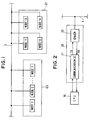
- FIG. 1 a plurality of nodes 1 to n and 11 to 14, each composed of an electronic control unit (ECU), are connected to a common data bus L.
- the nodes (ECUs) 1 to n which control an engine, an instrument panel, an airconditioner, etc, respectively, constitute a node group D0.
- the nodes 11 to 14 are ECUs, each mounted on a respective door of an automotive vehicle, for locking/unlocking the doors and opening/closing power windows, and constitute another node group D1. All the nodes are connected to the common data bus L and perform data transmission among them equally and independently (Multi-Task Access).
- each node includes a central processing unit (CPU) 10 and a communication unit 20 including a communication integrated circuit (IC) 21 and a driver 22.
- the communication IC 21 formulates data to be transmitted to other nodes upon receipt of information from the CPU 10.
- the data to be transmitted are coded according to the NRZ and the bit stuffing rule.
- the data transmission is performed under the transmission protocol called non-destructive CSMA/CD.
- the communication IC 21 transmits the coded data from a transmission terminal TX to the driver 22 and receives data sent from the driver 22 at a receiving terminal Rx.
- the driver 22 makes the signal level of the data to be transmitted through the common data bus a dominant level (HIGH level in this embodiment), when data collision occurs on the common bus.
- the dominant level means a level having a high priority and is sometimes referred to as an active level, and another level having a low priority (LOW level in this embodiment) is referred to as a recessive level, a passive level or an inactive level.
- FIG. 3 shows a frame format of the data to be transmitted.
- the frame consists of the following fields: SOF (Start of Frame), PRIORITY (transmission priority in case of collision), MESSAGE LENGTH (a length of a message), DESTINATION ID (an address of the node to which the data are to be transmitted), MESSAGE ID (a content of a message), DATA (data themselves), CRC (Cyclic Redundancy Check for detection of bit errors), EOM (End of Message), RSP (Response from a receiving node) and EOF (End of Frame).
- SOF Start of Frame
- PRIORITY transmission priority in case of collision
- MESSAGE LENGTH a length of a message
- DESTINATION ID an address of the node to which the data are to be transmitted
- MESSAGE ID a content of a message
- DATA data themselves
- CRC Cyclic Redundancy Check for detection of bit errors
- EOM End of Message
- RSP Re
- the SOF field is one bit long, having a dominant level indicating start of the frame.
- the PRIORITY field is 4 bits long, indicating priority of the frame when the transmission collision occurs on the common data bus. A signal “1 1 1 1” indicates the highest priority, and a signal "0000" indicates the lowest priority.
- the MESSAGE LENGTH field is 4 bits long, showing the number of bytes ML from the DESTINATION ID to the DATA.
- the DESTINATION ID field is 8 bits long, indicating an address to which the data is to be sent. The address shown therein is either address indicating individual nodes (individual ID), a group of nodes (group ID) or all nodes (broadcast ID).
- the MESSAGE ID field is 8 bits long, showing a content of the message.
- the DATA field has a variable length from one byte to eleven bytes, each byte being constituted by a 8 bits signal.
- the length of the DATA field is varied according to the data length to be sent.
- the CRC field is 8 bits long and contains a signal for checking bit errors.
- the EOM field is composed of an one bit recessive signal, a six bits dominant signal and another one bit recessive signal, the six bits dominant signal being interposed between both one bit recessive signals. Since the EOM includes the six consecutive dominant bits, it violates the bit stuffing rule because the bit stuffing rule used in the present embodiment does not permit consecutive dominant or recessive bits in excess of five.
- the bit stuffing rule violation is intentionally employed in the EOM so that the EOM signal is detected without fail at a receiving node.
- the RSP field is 2 bits long, and used as a field to show an one bit recessive signal and an one bit dominant signal sent from a receiving node when the receiving node receives the data successfully.
- the EOF field is composed of a six bits recessive signal indicating the end of a frame.
- a CRC calculation region includes the fields from PRIORITY to DATA, and an arbitration region includes the fields from PRIORITY to EOM.
- the bit stuffing rule is applied to the fields from SOF to CRC.
- the fields from DESTINATION ID to CRC are Placed between the MESSAGE LENGTH field and the EOM field. Since the DATA field, the length of which is variable, is interposed between MESSAGE LENGTH and EOM in the frame format, the frame error can be detected without fail, even when the number of bytes ML or the EOM signal is changed or deformed by noise during the data transmission. Therefore, reliability of the data transmission in the system is greatly enhanced.
- the EOM signal is composed of a six bits consecutive dominant signal interposed between one bit recessive signals, there always appear two signal edges in the EOM signal, and accordingly, the EOM signal is surely detected.
- the DESTINATION ID includes not only the individual ID designating an individual node and the broadcast ID designating all the nodes but also the group ID designating a group of nodes (as exemplified as the group D0 and the group D1 in FIG. 1) which frequently receive common data. Therefore, the data which are necessary to the group can be transmitted only to that group without sending unnecessary information to other groups, thereby alleviating an operational load imposed on CPUs.
- the group ID designating the group D0 is set as the DESTINATION ID
- the data for controlling the engine, the instrument panel and the airconditioner, etc. are transmitted to the group D0 without sending the same to the group D1.
- certain data are required by all the nodes, such data are transmitted to all of them under the broadcast ID. In this manner, the efficient data transmission can be carried out.
- a step 101 whether the SOF signal is received or not is checked.
- the process moves to a step 102 where the respective signals of PRIORITY, MESSAGE LENGTH (ML), DESTINATION ID AND MESSAGE ID are received.
- ML MESSAGE LENGTH
- DESTINATION ID AND MESSAGE ID are received.
- the process moves to 104 where the DATA signals are received.
- the number of the bytes received is incremented, and whether the byte-count has reached a number (ML-1) at a following step 106.
- the process returns to the step 103 and the cycle from the step 103 to the step 106 is repeated until the EOF signal is received at the step 103.
- the number ML represents the number of bytes indicated by the MESSAGE LENGTH which includes all the number of bytes from the DESTINATION ID to the DATA (refer to FIG. 3)
- the step 103 checks whether the EOF signal is received, and if YES, the process moves to a step 107. At the step 107, whether the byte-count is equal to (ML-1) is checked. The fact that the byte-count is equal to (ML-1) means that all the DATA bytes and the CRC byte have been received. Then, the process moves to a step 108 where the bit error is checked with the CRC. The result of the CRC error check is judged at a step 109, and if it is affirmative the process moves to a step 111 (in FIG. 5).
- Whether the DESTINATION ID accords with either one of the individual ID, the group ID or the broadcast ID is checked at steps 111, 112 or 113, respectively. If either one of the answers is YES, the process moves to a step 114 where the MESSAGE ID and the DATA are sent to the CPU 10. If the DESTINATION ID does not accord with any one of the IDs, then the data are not sent to the CPU 10, and the process returns to the step 101, thereby alleviating the load of the CPU 10. In case where either one of the answers of the steps 106, 107 and 109 is NO, then it is judged that the data are not received correctly, and the data received by that time are disposed, for example, by destroying the data at a step 110.
- the process can be easily programmed in an 8 bits CPU.
- the communication IC 21 is not limited to the one using a CPU, but it may be composed of hard logic elements. Further, it may be integrated in the CPU 10.
- the common data line L shown in FIG. 1 may be changed to a data line constituted by two transmission wires. In the frame format shown in FIG. 3, the positions of the MESSAGE LENGTH and the DESTINATION ID may be exchanged, or the MESSAGE LENGTH may be placed between the MESSAGE ID and the DATA.
- any HIGH bit starts with the two consecutive HIGH parts and any LOW bit starts with the single HIGH part, thereby making one edge at a position of a two-thirds distance from the start of HIGH bit and at a position of an one-third distance from the start of LOW bit.
- the NRZ coding rule may be used without combining the bit stuffing rule, if the Manchester or the PWM is applied to the EOF field. In this case, the EOF is detected because it violates the NRZ rule. Coding efficiency in this case, however, is somewhat sacrificed because two different coding rules are used in a frame.
- the Manchester rule or the PWM rule may be used as a main coding rule in a frame, while applying the NRZ only to the EOF field.
- a decoder circuit will be a little more complex, compared with the case of the embodiment described above.
- a data frame to be transmitted from a node to other nodes includes a message (DATA, etc) having a variable length interposed between a signal (MESSAGE LENGTH) indicating the length of the message and a signal (EOM) indicating the end of the message in the frame.
- the message and the signals are coded according to a coding rule such as NRZ, and a bit stuffing rule is applied to the signal (MESSAGE LENGTH) indicating the length of the message and the message (DATA, etc) while another rule violating the bit stuffing rule is applied to the signal (EOM) indicating the end of the message.
- the signal (EOM) indicating the end of the message is clearly detected at a receiving end because it is coded according to a rule different from the rule applied to the message and other signals. Further, since the length of the message actually received at the receiving end can be compared with the signal indicating the length of the message, transmission error can be detected without fail.
Landscapes
- Engineering & Computer Science (AREA)
- Computer Networks & Wireless Communication (AREA)
- Signal Processing (AREA)
- Computer Security & Cryptography (AREA)
- Small-Scale Networks (AREA)
- Communication Control (AREA)
Applications Claiming Priority (3)
| Application Number | Priority Date | Filing Date | Title |
|---|---|---|---|
| JP37552/97 | 1997-02-21 | ||
| JP09037552A JP3117000B2 (ja) | 1997-02-21 | 1997-02-21 | 通信システムおよびそれに使用される電子制御装置 |
| JP3755297 | 1997-02-21 |
Publications (3)
| Publication Number | Publication Date |
|---|---|
| EP0862296A2 true EP0862296A2 (fr) | 1998-09-02 |
| EP0862296A3 EP0862296A3 (fr) | 2000-01-05 |
| EP0862296B1 EP0862296B1 (fr) | 2005-03-23 |
Family
ID=12500695
Family Applications (1)
| Application Number | Title | Priority Date | Filing Date |
|---|---|---|---|
| EP98101002A Expired - Lifetime EP0862296B1 (fr) | 1997-02-21 | 1998-01-21 | Système de communication de données et unité de contrôle électronique utilisée dans celui-ci |
Country Status (4)
| Country | Link |
|---|---|
| US (1) | US6167057A (fr) |
| EP (1) | EP0862296B1 (fr) |
| JP (1) | JP3117000B2 (fr) |
| DE (1) | DE69829429T2 (fr) |
Cited By (6)
| Publication number | Priority date | Publication date | Assignee | Title |
|---|---|---|---|---|
| WO2000076108A1 (fr) * | 1999-06-02 | 2000-12-14 | Siemens Aktiengesellschaft | Procede de surveillance de la qualite de transmission de bits lors de la transmission orientee paquets |
| WO2003055152A1 (fr) * | 2001-11-06 | 2003-07-03 | Universitat Rovira I Virgili | Protocole de communication en serie a schema de fonctionnement maitre- esclave |
| DE102004013629A1 (de) * | 2004-03-19 | 2005-10-06 | Volkswagen Ag | Kommunikationssystem für ein Kraftfahrzeug |
| WO2007036800A3 (fr) * | 2005-09-28 | 2007-07-12 | Ati Technologies Inc | Procede et appareil de gestion d'erreurs |
| CN101222525B (zh) * | 2008-01-24 | 2010-07-14 | 浙江大学 | 自适应通信主体物理拓扑结构的多ecu消息通信方法 |
| EP2317411A3 (fr) * | 2000-12-08 | 2011-11-23 | The Boeing Company | Interface de dispositif de réseau pour interfacer numériquement des voies de données avec une unité de commande par l'intermédiaire d'un réseau |
Families Citing this family (17)
| Publication number | Priority date | Publication date | Assignee | Title |
|---|---|---|---|---|
| US6691172B1 (en) * | 1998-12-15 | 2004-02-10 | Honeywell International, Inc. | Communication system for defining a variable group of processors for receiving a transmitted communication |
| KR100376249B1 (ko) * | 2000-05-29 | 2003-03-15 | 퍼스널 텔레콤 주식회사 | 메시지 길이에 따른 가변형 에러 제어 방법 |
| US7020156B2 (en) * | 2000-12-15 | 2006-03-28 | American Standard International Inc. | Multiple device communications |
| US7012927B2 (en) * | 2001-02-06 | 2006-03-14 | Honeywell International Inc. | High level message priority assignment by a plurality of message-sending nodes sharing a signal bus |
| US7546511B2 (en) | 2001-12-05 | 2009-06-09 | Lg Electronics Inc. | Error detection code generating method and error detection code generator |
| US7082479B2 (en) * | 2002-06-19 | 2006-07-25 | Eastman Kodak Company | System and method for maintaining synchronized data transfer using a plurality of different control words individually indicative of the same single event |
| SE0401091L (sv) * | 2004-04-28 | 2005-10-29 | Sven Nils Johannes Linnman | Metod att konfigurera ett bussystem |
| JP2005334080A (ja) * | 2004-05-24 | 2005-12-08 | Olympus Corp | 被検体内導入装置および医療装置 |
| US7769932B2 (en) * | 2005-09-09 | 2010-08-03 | Honeywell International, Inc. | Bitwise arbitration on a serial bus using arbitrarily selected nodes for bit synchronization |
| EP2057515B1 (fr) * | 2006-08-08 | 2018-05-02 | Siemens Industry, Inc. | Dispositifs, systèmes et procédés pour l'attribution d'une adresse de module plc |
| US7680144B2 (en) * | 2006-09-12 | 2010-03-16 | Honeywell International Inc. | Device coupled between serial busses using bitwise arbitration |
| US8688129B2 (en) * | 2007-09-17 | 2014-04-01 | Qualcomm Incorporated | Grade of service (GoS) differentiation in a wireless communication network |
| US8503465B2 (en) * | 2007-09-17 | 2013-08-06 | Qualcomm Incorporated | Priority scheduling and admission control in a communication network |
| JP5091292B2 (ja) * | 2010-09-15 | 2012-12-05 | 株式会社日本自動車部品総合研究所 | 通信システム、トランシーバ、ノード |
| TWI466650B (zh) * | 2010-11-08 | 2015-01-01 | Ind Tech Res Inst | 鍋具及其製造方法 |
| DE102014113456B4 (de) * | 2014-09-18 | 2019-03-14 | Infineon Technologies Ag | Sensorvorrichtung und sensoranordnung |
| CN110875911B (zh) * | 2018-09-03 | 2022-03-04 | 厦门奇力微电子有限公司 | 支持自动识别单个数据包数据位数的通信协议及通信方法 |
Family Cites Families (7)
| Publication number | Priority date | Publication date | Assignee | Title |
|---|---|---|---|---|
| DE3546662C3 (de) * | 1985-02-22 | 1997-04-03 | Bosch Gmbh Robert | Verfahren zum Betreiben einer Datenverarbeitungsanlage |
| US4715031A (en) * | 1985-09-23 | 1987-12-22 | Ford Motor Company | Vehicular data transfer communication system |
| JPH0771088B2 (ja) * | 1987-04-06 | 1995-07-31 | 古河電気工業株式会社 | 多重伝送方式 |
| JP2904296B2 (ja) * | 1990-03-30 | 1999-06-14 | マツダ株式会社 | 車両用多重伝送装置 |
| KR100201580B1 (ko) * | 1991-04-02 | 1999-06-15 | 후루까와 준노스께 | 다중전송시스템 |
| JP3042549B2 (ja) * | 1991-08-23 | 2000-05-15 | 古河電気工業株式会社 | 多重伝送方式の受信応答方法 |
| EP0612169B1 (fr) * | 1993-02-15 | 2001-11-07 | Honda Giken Kogyo Kabushiki Kaisha | Procédé et dispositif de transmission de données |
-
1997
- 1997-02-21 JP JP09037552A patent/JP3117000B2/ja not_active Expired - Lifetime
-
1998
- 1998-01-21 EP EP98101002A patent/EP0862296B1/fr not_active Expired - Lifetime
- 1998-01-21 DE DE69829429T patent/DE69829429T2/de not_active Expired - Lifetime
- 1998-02-19 US US09/026,181 patent/US6167057A/en not_active Expired - Lifetime
Cited By (12)
| Publication number | Priority date | Publication date | Assignee | Title |
|---|---|---|---|---|
| WO2000076108A1 (fr) * | 1999-06-02 | 2000-12-14 | Siemens Aktiengesellschaft | Procede de surveillance de la qualite de transmission de bits lors de la transmission orientee paquets |
| EP2317411A3 (fr) * | 2000-12-08 | 2011-11-23 | The Boeing Company | Interface de dispositif de réseau pour interfacer numériquement des voies de données avec une unité de commande par l'intermédiaire d'un réseau |
| WO2003055152A1 (fr) * | 2001-11-06 | 2003-07-03 | Universitat Rovira I Virgili | Protocole de communication en serie a schema de fonctionnement maitre- esclave |
| DE102004013629A1 (de) * | 2004-03-19 | 2005-10-06 | Volkswagen Ag | Kommunikationssystem für ein Kraftfahrzeug |
| US8634968B2 (en) | 2004-03-19 | 2014-01-21 | Audi Ag | Communication system for a motor vehicle |
| DE102004013629B4 (de) | 2004-03-19 | 2023-06-01 | Volkswagen Ag | Kommunikationssystem für ein Kraftfahrzeug |
| WO2007036800A3 (fr) * | 2005-09-28 | 2007-07-12 | Ati Technologies Inc | Procede et appareil de gestion d'erreurs |
| US7596743B2 (en) | 2005-09-28 | 2009-09-29 | Ati Technologies Inc. | Method and apparatus for error management |
| US8127208B2 (en) | 2005-09-28 | 2012-02-28 | Ati Technologies Ulc | Method and apparatus for error management |
| US8667375B2 (en) | 2005-09-28 | 2014-03-04 | Ati Technologies Ulc | Method and apparatus for error management |
| US8769384B2 (en) | 2005-09-28 | 2014-07-01 | Ati Technologies Ulc | Method and apparatus for error management |
| CN101222525B (zh) * | 2008-01-24 | 2010-07-14 | 浙江大学 | 自适应通信主体物理拓扑结构的多ecu消息通信方法 |
Also Published As
| Publication number | Publication date |
|---|---|
| US6167057A (en) | 2000-12-26 |
| JPH10233789A (ja) | 1998-09-02 |
| EP0862296A3 (fr) | 2000-01-05 |
| DE69829429T2 (de) | 2006-04-13 |
| EP0862296B1 (fr) | 2005-03-23 |
| DE69829429D1 (de) | 2005-04-28 |
| JP3117000B2 (ja) | 2000-12-11 |
Similar Documents
| Publication | Publication Date | Title |
|---|---|---|
| US6167057A (en) | Data communication system and electronic control unit used therein | |
| EP1022878B1 (fr) | Dispositif de transmission de données | |
| US5572658A (en) | Network interface | |
| US5383185A (en) | Method and apparatus for data collision detection in a multi-processor communication system | |
| CN114124607A (zh) | Can收发器 | |
| US20030226065A1 (en) | Controller area network controller for making a self-diagnosis of a function | |
| US5293571A (en) | Receipt acknowledgement method in multiplex transmission | |
| Specification | Bosch | |
| US12432087B2 (en) | Delay module for a controller area network (CAN), a CAN device, and a method for the delay module | |
| US20210036813A1 (en) | User station for a serial bus system and method for error signaling for a message received in a serial bus system | |
| JP4220208B2 (ja) | 確定的フィールドバス及びその種のバスの管理方法 | |
| Hafeez et al. | State of the art survey on comparison of can, flexray, lin protocol and simulation of lin protocol | |
| JPH08256193A (ja) | インターフェースのパラメータを自動的に整合させるための方法 | |
| US6987776B1 (en) | Multiplex communication method, the device and the system thereof | |
| KR960009471B1 (ko) | 다중전송방법 | |
| US5101198A (en) | Method and device for the transmission of data between stations of a communications network, in particular for motor vehicles | |
| JP3252556B2 (ja) | 通信装置 | |
| JP2781397B2 (ja) | 多重伝送装置 | |
| JP2857655B2 (ja) | 車両用データ伝送システム | |
| US20020095637A1 (en) | Method of communication with improved acknowledgment of reception | |
| JP7834236B2 (ja) | シリアルバスシステムの加入者局およびシリアルバスシステムにおける通信方法 | |
| EP4657803A1 (fr) | Module de connexion à un émetteur-récepteur, dispositif et procédé pour le module | |
| JP2784709B2 (ja) | 車両用データ伝送システム | |
| JP2624265B2 (ja) | データ伝送装置 | |
| JP2947437B2 (ja) | データ伝送方法 |
Legal Events
| Date | Code | Title | Description |
|---|---|---|---|
| PUAI | Public reference made under article 153(3) epc to a published international application that has entered the european phase |
Free format text: ORIGINAL CODE: 0009012 |
|
| AK | Designated contracting states |
Kind code of ref document: A2 Designated state(s): DE FR GB |
|
| AX | Request for extension of the european patent |
Free format text: AL;LT;LV;MK;RO;SI |
|
| PUAL | Search report despatched |
Free format text: ORIGINAL CODE: 0009013 |
|
| AK | Designated contracting states |
Kind code of ref document: A3 Designated state(s): AT BE CH DE DK ES FI FR GB GR IE IT LI LU MC NL PT SE |
|
| AX | Request for extension of the european patent |
Free format text: AL;LT;LV;MK;RO;SI |
|
| 17P | Request for examination filed |
Effective date: 20000704 |
|
| AKX | Designation fees paid |
Free format text: DE FR GB |
|
| 17Q | First examination report despatched |
Effective date: 20021015 |
|
| GRAP | Despatch of communication of intention to grant a patent |
Free format text: ORIGINAL CODE: EPIDOSNIGR1 |
|
| GRAS | Grant fee paid |
Free format text: ORIGINAL CODE: EPIDOSNIGR3 |
|
| GRAA | (expected) grant |
Free format text: ORIGINAL CODE: 0009210 |
|
| AK | Designated contracting states |
Kind code of ref document: B1 Designated state(s): DE FR GB |
|
| REG | Reference to a national code |
Ref country code: GB Ref legal event code: FG4D |
|
| REF | Corresponds to: |
Ref document number: 69829429 Country of ref document: DE Date of ref document: 20050428 Kind code of ref document: P |
|
| PLBE | No opposition filed within time limit |
Free format text: ORIGINAL CODE: 0009261 |
|
| STAA | Information on the status of an ep patent application or granted ep patent |
Free format text: STATUS: NO OPPOSITION FILED WITHIN TIME LIMIT |
|
| ET | Fr: translation filed | ||
| 26N | No opposition filed |
Effective date: 20051227 |
|
| REG | Reference to a national code |
Ref country code: FR Ref legal event code: PLFP Year of fee payment: 18 |
|
| REG | Reference to a national code |
Ref country code: FR Ref legal event code: PLFP Year of fee payment: 19 |
|
| REG | Reference to a national code |
Ref country code: FR Ref legal event code: PLFP Year of fee payment: 20 |
|
| PGFP | Annual fee paid to national office [announced via postgrant information from national office to epo] |
Ref country code: FR Payment date: 20161215 Year of fee payment: 20 |
|
| PGFP | Annual fee paid to national office [announced via postgrant information from national office to epo] |
Ref country code: DE Payment date: 20170117 Year of fee payment: 20 |
|
| PGFP | Annual fee paid to national office [announced via postgrant information from national office to epo] |
Ref country code: GB Payment date: 20170118 Year of fee payment: 20 |
|
| REG | Reference to a national code |
Ref country code: DE Ref legal event code: R071 Ref document number: 69829429 Country of ref document: DE |
|
| REG | Reference to a national code |
Ref country code: GB Ref legal event code: PE20 Expiry date: 20180120 |
|
| PG25 | Lapsed in a contracting state [announced via postgrant information from national office to epo] |
Ref country code: GB Free format text: LAPSE BECAUSE OF EXPIRATION OF PROTECTION Effective date: 20180120 |