EP0862336A2 - Détection automatique de l'équilibrage du blanc dans un image capturée par une caméra numérique - Google Patents
Détection automatique de l'équilibrage du blanc dans un image capturée par une caméra numérique Download PDFInfo
- Publication number
- EP0862336A2 EP0862336A2 EP98301419A EP98301419A EP0862336A2 EP 0862336 A2 EP0862336 A2 EP 0862336A2 EP 98301419 A EP98301419 A EP 98301419A EP 98301419 A EP98301419 A EP 98301419A EP 0862336 A2 EP0862336 A2 EP 0862336A2
- Authority
- EP
- European Patent Office
- Prior art keywords
- color
- image
- pixel
- captured image
- light
- Prior art date
- Legal status (The legal status is an assumption and is not a legal conclusion. Google has not performed a legal analysis and makes no representation as to the accuracy of the status listed.)
- Granted
Links
- 238000012937 correction Methods 0.000 title claims description 4
- 238000001514 detection method Methods 0.000 title claims 2
- 238000001228 spectrum Methods 0.000 claims description 13
- 238000012545 processing Methods 0.000 claims description 9
- 238000013507 mapping Methods 0.000 claims description 5
- 238000005286 illumination Methods 0.000 claims description 4
- 238000005070 sampling Methods 0.000 claims description 4
- 230000003595 spectral effect Effects 0.000 claims description 4
- 230000003287 optical effect Effects 0.000 claims description 2
- 230000009466 transformation Effects 0.000 claims 6
- 238000000844 transformation Methods 0.000 claims 1
- 238000000034 method Methods 0.000 abstract description 12
- 230000006870 function Effects 0.000 description 9
- WFKWXMTUELFFGS-UHFFFAOYSA-N tungsten Chemical compound [W] WFKWXMTUELFFGS-UHFFFAOYSA-N 0.000 description 8
- 229910052721 tungsten Inorganic materials 0.000 description 8
- 239000010937 tungsten Substances 0.000 description 8
- 238000006243 chemical reaction Methods 0.000 description 7
- 230000002093 peripheral effect Effects 0.000 description 6
- 238000007906 compression Methods 0.000 description 3
- 230000006835 compression Effects 0.000 description 3
- 230000002596 correlated effect Effects 0.000 description 2
- 238000013144 data compression Methods 0.000 description 2
- 238000010586 diagram Methods 0.000 description 2
- 238000011010 flushing procedure Methods 0.000 description 2
- 239000003086 colorant Substances 0.000 description 1
- 230000001419 dependent effect Effects 0.000 description 1
- 238000012986 modification Methods 0.000 description 1
- 230000004048 modification Effects 0.000 description 1
Images
Classifications
-
- H—ELECTRICITY
- H04—ELECTRIC COMMUNICATION TECHNIQUE
- H04N—PICTORIAL COMMUNICATION, e.g. TELEVISION
- H04N23/00—Cameras or camera modules comprising electronic image sensors; Control thereof
- H04N23/80—Camera processing pipelines; Components thereof
- H04N23/84—Camera processing pipelines; Components thereof for processing colour signals
- H04N23/88—Camera processing pipelines; Components thereof for processing colour signals for colour balance, e.g. white-balance circuits or colour temperature control
Definitions
- This invention relates to digital cameras, and more particularly to a method and apparatus for performing color adjustment upon images taken with a digital camera.
- Digital still cameras are being developed today to allow an image to be captured, digitized, stored, and reproduced using conventional printers coupled to a conventional personal computer.
- an array ofcharge-coupled-device (CCD) detectors are used to capture the image.
- CCD charge-coupled-device
- Each detector of the CCD array is used to capture one portion of the image.
- an electrical charge representative of the intensity of the light to which the detector has been exposed is accumulated. This charge can be coupled to an A/D (analog to digital) converter.
- the AID convertor produces a digital value that represents the charge on each of the detectors, and thus the intensity of the light received by each detector.
- color filters are placed before each detector of the CCD array. Accordingly, a detector which is associated with a filter that passes essentially only red light will form a red detector.
- the color detectors are frequently arranged in groups. For example, in one well known arrangement, two green detectors. a blue detector. and a red detector form a two by two grouping. This grouping is repeated throughout the array of detectors. By taking the digital value associated with each detector. the color composition of the image is captured.
- each detector may be altered due to the composition of the spectrum of light emitted by the particular light source which illuminates the image. For example, if an image is illuminated by a tungsten light source, then the image will be shifted toward the red spectrum, since tungsten light sources emit more red light than blue or green light. This shift will give the resulting photograph an undesirable reddish/orangish appearance.
- variable gain amplifiers are provided in line with the red and blue signals.
- the amount of gain applied to the red and blue signals is adjusted to compensate for the type of light which illuminates the image.
- a manual control on the camera allows the user to select between tungsten mode and daylight mode. In tungsten mode, the gains of the amplifiers that are responsible for amplifying the output from the red and blue detectors are set to a first gain ratio to compensate for the blue shift. In daylight mode, a second gain ratio is used which causes the gain of the amplifiers responsible for amplifying the red and blue signals to be approximately equal to the amount of gain which is set for the green signals.
- Selection of the particular gain ratio is also dependent upon the state of a relay.
- the relay overrides the manual control when a flash has been charged, since the use of a flash will alter the color composition of the image. That is, the gain ratio of the color signal amplifiers should be essentially the same when capturing an image using a flash device and when capturing an image during daylight. Therefore, when a flash device is charged to illuminate an image, the relay sets the mode of the variable gain amplifiers to the daylight setting, as is appropriate in the case in which a flash is to be used. Thus. by altering the gain of the amplifiers responsible for amplifying the outputs from the red and blue detectors, the color is properly balanced for the case in which an image is to be captured in tungsten lighting, daylight, or when a flash is used.
- this system can improperly adjust the color of the image that is captured if the flash is charged, but not actually activated.
- the amount of color adjustment that is preformed is essentially fixed at one of two particular ratios (i.e., the gain of the amplifiers is set to one of two levels). Accordingly, if the amount of color adjustment that is required is other than that which would be desirable if the image were illuminated solely by tungsten or solely by natural sunlight, then the color of the image will be improperly adjusted. Still further, not every tungsten light source will have exactly the same color temperature (spectral composition of wavelengths).
- a common way in which digital cameras have attempted to white balance an image requires that a preview image be taken.
- the preview image is used to determine the amount of adjustment that is required in order to white balance the image.
- the adjustment will be incorrect if the illumination of the image differs between the time the preview image is taken and the time the final image is taken. For example, if the preview image is taken without a flash, and the final image is taken with a flash, then the correction that is made to the final image based upon the characteristics of the preview image will be incorrect. A number of other situations can arise which would cause the illumination of the preview image to differ from the illumination of the final image. For example. the sun may become obscured by a cloud. a light may be turned on or off. etc.
- the color adjustment is determined in a way that accurately reflects the characteristics of the final image. Furthermore, it would be desirable to provide a system wherein the amount of color adjustment can be adjusted to compensate for several different conditions and combinations of light sources.
- the present invention is a method and apparatus for performing color balance of an image taken with a digital camera using either an host computer that is external to the camera or in a device internal to the camera using the image data of the image to be white balance adjusted in order to determine the amount of adjustment required.
- a digital image is captured by: first flushing, at a first point in time, any charge which has accumulated on a CCD light detector array; allowing light to strike the CCD detector after the detector has been flushed; and determining the amount of charge that has accumulated upon the detectors that comprise the array.
- white balancing is typically required if the light source that illuminates objects to be imaged has a "color temperature" that would cause the image to be tinted or biased in favor of, or away from, one color. For example, a tungsten light source will typically be biased in favor red. Therefore, in order for the image to be properly white balanced, the red component of each pixel must be adjusted with respect to the blue and green components of each pixel.
- the amount of the adjustment which is to be made is determined by analysis of the image data to be adjusted (i.e., the "picture image").
- image pixels within the picture image are mapped into a two dimensional space, the two dimensions of this space being red/blue and green/blue.
- Image pixels that make up a reference image that was illuminated by a reference light source are then plotted in the two dimensional space.
- Each of the points at the periphery of the picture image are mapped into points at the periphery of the reference image by a transform.
- the transforms that are used to map the points in the picture image to the points in the reference image are then plotted in a transform space.
- a shape is defined in the transform space by the set of transforms associated with each of the points on the periphery of the picture image. Accordingly, a set of such shapes in the transform space will be defined for the picture image. The intersection of these shapes is then used to determine source of light that illuminates the picture image and the adjustment factors required to properly white balance the picture image.
- the analysis and adjustment ofthe image data is performed in the camera.
- the adjustment is performed outside the camera by a host device, such as a personal computer or printer.
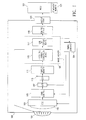
- Fig. 1 is a block diagram of a digital camera in accordance with the present invention.
- the present invention is a method and apparatus for performing automatic white balance on an image captured by a digital camera based upon characteristics of a light source as determined from an analysis of the image data.
- FIG. 1 is a block diagram of one embodiment of a digital camera 100 in accordance with the present invention.
- the digital camera 100 includes: an optical lens 101; an array of charge-coupled-device (CCD) detectors 103, including an array of color filters, each filter associated with a detector; a gain control circuit 105 ; an A/D (analog to digital) convertor 107; a control device 109 (such as a microprocessor), preferably including a JPEG file format conversion device 115 and an EXIF file format device 117; a buffer memory 111; an image processing device 113, such as a DSP (digital signal processor); an image memory device 119; and an output port 120.
- CCD charge-coupled-device
- the digital camera 100 Light enters the digital camera 100 through the lens 101 and is focused on the array of CCD detectors 103.
- the color filters 102 associated with each detector within the CCD array 103 cause the detectors to be sensitive to one particular color.
- the CCD detectors are configured in a repeating pattern of two by two groups in which the top right detector is sensitive to red light, the top left detector is sensitive to blue green light, the bottom right detector is sensitive to green light, and the bottom left detector is sensitive to blue light. It should be understood that the array of detectors may be fabricated such that the particular detectors are sensitive to other colors and are arranged in other configurations.
- a timing generator 104 is coupled to the CCD detector array 103.
- the timing generator 104 controls the reading of the CCD detector array 103 in essentially conventional fashion.
- the timing generator 104 causes the charge accumulated by each detector to be serially applied to the input of the gain control device 105.
- the control device 109 is coupled to the timing generator and controls the operation of the timing generator 104 in essentially conventional fashion.
- the timing generator 104 is capable of flushing the CCD array 103 to essentially discharge any charge previously accumulated the detectors within the array.
- the light that passes through the lens and the color filters causes charge to accumulate on each of the detectors within the CCD array 103 in an amount that is proportional to the amount of light that strikes each detector.
- the charge that accumulates on each detector within the CCD array 103 results in a voltage that is coupled to the gain control circuit 105.
- the gain control circuit 105 includes an automatic gain control circuit and circuitry to implement a correlated double sampling process.
- the correlated double sampling piocess is a conventional process which accounts for overshoot and undershoot in the output from the CCD detectors as the CCD array is read.
- the control device 109 is coupled to the gain control device and controls the automatic gain control circuit.
- the output from the gain control circuit 105 is coupled to the A/D converter 107.
- the AID converter 107 converts to digital values the voltages read from the CCD detectors and processed by the gain control circuit 105. The resulting digital values are preferably directly proportional to the amount of light detected by each detector.
- the A/D converter 107 is coupled to the DSP 113.
- the DSP 113 processes the color information stored in the buffer memory 111 to provide a demosaic function. to perform automatic white balance, and to sharpen the image.
- the DSP 113 determines which values are coupled from the A/D converter 107 to the DSP 113 are associated with which detectors by the order in which the values are received from the A/D converter 107.
- the demosaic function and the automatic white balance functions are conventional functions.
- the DSP 113 is a Part No. HD49811TFA commercially available from Hitachi and the automatic white balance function is provided in the HD49811TFA data sheet distributed by Hitachi.
- the output from the DSP 113 is a set of image pixels, each of which represent the color of a particular portion of the image that was captured by the CCD detector array 103. Accordingly, the complete set of image pixels comprise the image data.
- the image data is stored in a buffer memory 111.
- the buffer memory 111 is read by the control device 109.
- the control device 109 includes a conventional dedicated integrated circuit which performs a JPEG file format conversion. Therefore, in accordance with one embodiment of the present invention, a combination of hardware and software executed within the control device 109 operate together to form a JPEG file format conversion device 115.
- the JPEG file format conversion device comprises only hardware.
- the JPEG file format conversion device 115 is a software routine performed within a programmable control device 109. In either case, file format conversion is performed in conventional fashion.
- no compression is performed.
- compression is performed in accordance with a standard other than JPEG.
- the JPEG file format conversion process compresses the information output from the DSP 113 and stored in the buffer 111 in accordance with the well known JPEG data compression standard.
- the information which is in JPEG format is then embedded within a file which conforms to "Digital Still Camera Image File Format Standard” (Version 1.0. July 13. 1995) (commonly known as "EXIF”). defined by the JEIDA Electronic Still Camera Technical Committee.
- the file is embedded within the EXIF file by an EXIF file format device 117 within the control device 109.
- the EXIF file format device is a combination of software executed within the control device 109 and dedicated hardware.
- the EXIF file format device 117 is a software routine performed within the control device 109.
- the EXIF file format device 117 comprises only dedicated hardware.
- the image information is compressed in accordance with the well known JPEG data compression technique and presented in YC b C r format with 4:2:2 subsampling.
- the EXIF file is then transferred to a host for further processing.
- the output from the DSP 113 may be formatted in any manner which allows a host 121, such as a personal computer or printer, to read and interpret the information provided by the camera 100 to the host 121.
- the image data is not compressed.
- the image data is analyzed to determine how to adjust the digital values in the image data to correct for differences in the characteristics of the light source used to illuminate the image.
- the image data is analyzed to determine the amount of adjustment to be applied to the image data to properly white balance the image.
- the analysis involves mathematical manipulation of the image data which can be performed by a programmable device, such as a microprocessor or DSP either within or external to the camera (e.g., in the host).
- the image data is analyzed with respect to a reference image.
- the reference image preferably has an essentially full spectrum of visible wavelengths and is illuminated by a reference light source.
- the image data for the reference image is mapped into a two dimensional space in which the horizontal axis is red divided by blue and the vertical axis is green divided by blue.
- This mapping reduces the three dimensional (rgb) points to chromaticity defined by two values (i.e., the red/blue value and the green/blue value). Accordingly, a gamut of points can be plotted in this two dimensional space.
- each point representing the color of one pixel in the reference image.
- a set of points which, when connected from one point to the next, define the outer most boundary of this reference gamut are identified. These peripheral points are then saved.
- a picture image can be analyzed with respect to the reference image by first mapping the picture image into the two-dimensional space such that each pixel defines a point in the two-dimensional space. Then peripheral points for the picture image are determined. Each one of these points are than mapped to one of the peripheral points of the reference image.
- the transform that is used to map the peripheral point of the picture image to the peripheral point of the reference image is then defined by two values. The first value is the quotient of the red/blue values, and the second value is the quotient of the green/blue values.
- Each set of transforms associated with one point of the picture image and mapped to each point in the reference image will define a shape.
- a set of shapes will be defined by mapping each of the points in the picture image to each of the points in the reference image. The intersection of these shapes defines a new shape. This new shape can then be analyzed to determine the light source which most likely was used to illuminate the scene.
- the image data may be analyzed by any other methods for determining the adjustment required to color balance the image.
- the device for analyzing the image data is provided within the camera.
- the DSP 113 performs the analysis of the image data.
- the color of the image pixels that make-up the image are adjusted to achieve proper white balance.
- the image data may not be compressed. or the compression may be applied after either analysis of the image data or after the adjustments to the color balance are made.
- the components of the digital camera are described as one example of devices which perform particular functions within a digital camera. Accordingly, the functions which are described as being performed within the digital camera may be performed by any device that is capable of performing the particular functions.
- the control device 109 may be a microprocessor, an application specific integrated circuit, a discrete circuit, a state machine, or any other circuit or component that is capable of performing the functions that are described above. Accordingly, it is to be understood that the invention is not to be limited by the specific illustrated embodiments, but only by the scope of the appended claims.
Landscapes
- Engineering & Computer Science (AREA)
- Multimedia (AREA)
- Signal Processing (AREA)
- Color Television Image Signal Generators (AREA)
- Processing Of Color Television Signals (AREA)
Applications Claiming Priority (2)
| Application Number | Priority Date | Filing Date | Title |
|---|---|---|---|
| US808918 | 1985-12-13 | ||
| US08/808,918 US6411331B1 (en) | 1997-02-28 | 1997-02-28 | Automatic white balance detection and correction of an image captured in a digital camera |
Publications (3)
| Publication Number | Publication Date |
|---|---|
| EP0862336A2 true EP0862336A2 (fr) | 1998-09-02 |
| EP0862336A3 EP0862336A3 (fr) | 2000-05-10 |
| EP0862336B1 EP0862336B1 (fr) | 2004-04-21 |
Family
ID=25200114
Family Applications (1)
| Application Number | Title | Priority Date | Filing Date |
|---|---|---|---|
| EP98301419A Expired - Lifetime EP0862336B1 (fr) | 1997-02-28 | 1998-02-26 | Détection automatique de l'équilibrage du blanc dans un image capturée par une caméra numérique |
Country Status (4)
| Country | Link |
|---|---|
| US (1) | US6411331B1 (fr) |
| EP (1) | EP0862336B1 (fr) |
| JP (1) | JPH10243415A (fr) |
| DE (1) | DE69823254T2 (fr) |
Cited By (1)
| Publication number | Priority date | Publication date | Assignee | Title |
|---|---|---|---|---|
| US7009733B2 (en) | 2001-07-02 | 2006-03-07 | Coral Corporation | Manual correction of an image color |
Families Citing this family (24)
| Publication number | Priority date | Publication date | Assignee | Title |
|---|---|---|---|---|
| US6310647B1 (en) * | 1997-04-15 | 2001-10-30 | Eastman Kodak Company | Image format for storing digital images and including multiple application segments |
| US7030917B2 (en) * | 1998-10-23 | 2006-04-18 | Hewlett-Packard Development Company, L.P. | Image demosaicing and enhancement system |
| JP4532613B2 (ja) * | 1998-11-25 | 2010-08-25 | キヤノン株式会社 | 撮像方法及び装置並びに記憶媒体 |
| JP3532781B2 (ja) * | 1999-02-12 | 2004-05-31 | 株式会社メガチップス | 画像入力装置の画像処理回路 |
| JP2001128191A (ja) * | 1999-08-18 | 2001-05-11 | Fuji Photo Film Co Ltd | 画像処理方法および装置並びに記録媒体 |
| US7019776B1 (en) * | 2002-08-16 | 2006-03-28 | Magnachip Semiconductor, Inc. | Method and system for automatic white balancing |
| US7173655B2 (en) * | 2002-10-18 | 2007-02-06 | Hewlett-Packard Development Company, L.P. | Capture of sensory data in association with digital still images |
| US7209167B2 (en) * | 2003-01-15 | 2007-04-24 | Hewlett-Packard Development Company, L.P. | Method and apparatus for capture of sensory data in association with image data |
| US7257278B2 (en) * | 2003-02-26 | 2007-08-14 | Hewlett-Packard Development Company, L.P. | Image sensor for capturing and filtering image data |
| US20050046739A1 (en) * | 2003-08-29 | 2005-03-03 | Voss James S. | System and method using light emitting diodes with an image capture device |
| US7394488B2 (en) * | 2003-10-30 | 2008-07-01 | Hewlett-Packard Development Company, L.P. | System and method for dual white balance compensation of images |
| US7763918B1 (en) | 2004-12-02 | 2010-07-27 | Chen Feng | Image pixel design to enhance the uniformity of intensity distribution on digital image sensors |
| US7564629B1 (en) * | 2004-12-02 | 2009-07-21 | Crosstek Capital, LLC | Microlens alignment procedures in CMOS image sensor design |
| US7450161B1 (en) * | 2004-12-02 | 2008-11-11 | Magnachip Semiconductor Ltd. | System and method to enhance the uniformity of intensity distribution on digital imaging sensors |
| US8074272B2 (en) | 2005-07-07 | 2011-12-06 | Microsoft Corporation | Browser security notification |
| US7865830B2 (en) * | 2005-07-12 | 2011-01-04 | Microsoft Corporation | Feed and email content |
| US7831547B2 (en) * | 2005-07-12 | 2010-11-09 | Microsoft Corporation | Searching and browsing URLs and URL history |
| US7715657B2 (en) * | 2006-02-17 | 2010-05-11 | Microsoft Corporation | Method, device and program for detecting perceptual features of a larger image and incorporating information of the detected perceptual features into a smaller preview image |
| US7979803B2 (en) | 2006-03-06 | 2011-07-12 | Microsoft Corporation | RSS hostable control |
| US8213714B1 (en) * | 2008-05-18 | 2012-07-03 | Pixim Israel Ltd. | Method, device and computer program product for performing a gamut based white balance of a digital image |
| US8290258B1 (en) * | 2008-05-18 | 2012-10-16 | Pixim Israel Ltd. | Method, device and computer program product for performing a color based white balance of a digital image |
| US8921748B2 (en) * | 2011-05-19 | 2014-12-30 | Lockheed Martin Corporation | Optical window and detection system employing the same |
| US9568280B1 (en) | 2013-11-25 | 2017-02-14 | Lockheed Martin Corporation | Solid nose cone and related components |
| US9534868B1 (en) | 2014-06-03 | 2017-01-03 | Lockheed Martin Corporation | Aerodynamic conformal nose cone and scanning mechanism |
Family Cites Families (26)
| Publication number | Priority date | Publication date | Assignee | Title |
|---|---|---|---|---|
| US4050085A (en) | 1969-06-04 | 1977-09-20 | Hughes Aircraft Company | Automatic light control system |
| US3822393A (en) | 1972-10-11 | 1974-07-02 | Berkey Photo Inc | Electronic strobe |
| US4714962A (en) * | 1976-08-27 | 1987-12-22 | Levine Alfred B | Dual electronic camera, previewing, and control |
| US4366501A (en) | 1978-04-23 | 1982-12-28 | Canon Kabushiki Kaisha | Image recording system |
| JPS55124380A (en) | 1979-03-19 | 1980-09-25 | Canon Inc | Television camera |
| US4564856A (en) | 1981-04-09 | 1986-01-14 | Harris Corporation | Apparatus providing automatic and manual control of setup adjustments for TV cameras |
| US4635126A (en) | 1981-12-18 | 1987-01-06 | Canon Kabushiki Kaisha | Image pick-up system |
| JPS58147721A (ja) | 1982-02-26 | 1983-09-02 | Canon Inc | スチルビデオカメラ |
| US4495520A (en) | 1982-04-09 | 1985-01-22 | The United States Of America As Represented By The Administrator Of The National Aeronautics And Space Administration | Television camera video level control system |
| US4525741A (en) | 1982-11-03 | 1985-06-25 | Ncr Corporation | Self-adjusting video camera |
| DE3342992A1 (de) | 1982-11-29 | 1984-05-30 | Canon K.K., Tokio/Tokyo | Bildwandlereinrichtung |
| US4509077A (en) | 1982-12-17 | 1985-04-02 | Ncr Canada Ltd-Ncr Canada Ltee | Automatic, self-diagnosing, electro-optical imaging system |
| US4589023A (en) | 1982-12-20 | 1986-05-13 | Asahi Kogaku Kogyo Kabushiki Kaisha | Electronic camera |
| JPS59115676A (ja) | 1982-12-22 | 1984-07-04 | Canon Inc | 撮像装置 |
| US4532918A (en) | 1983-10-07 | 1985-08-06 | Welch Allyn Inc. | Endoscope signal level control |
| US4677489A (en) | 1984-09-19 | 1987-06-30 | Canon Kabushiki Kaisha | Image pickup apparatus |
| US5617139A (en) * | 1987-09-10 | 1997-04-01 | Canon Kabushiki Kaisha | Image pickup apparatus |
| US5134487A (en) | 1989-11-06 | 1992-07-28 | Canon Kabushiki Kaisha | Using common circuitry for different signals |
| JPH03238992A (ja) * | 1990-02-15 | 1991-10-24 | Sony Corp | ビデオカメラ装置 |
| US5295204A (en) * | 1991-07-18 | 1994-03-15 | Eastman Kodak Company | Method for color balancing a computer input scanner incorporating multiple scanning modes |
| JP3163660B2 (ja) * | 1991-07-31 | 2001-05-08 | ソニー株式会社 | カラービデオカメラのホワイトバランス調整装置 |
| US5589879A (en) * | 1993-03-26 | 1996-12-31 | Fuji Photo Film Co., Ltd. | Performing white balance correction on integrated divided areas of which average color is substantially white |
| US5563655A (en) | 1994-02-28 | 1996-10-08 | Eastman Kodak Company | Intelligent digital image storage for an electronic camera |
| KR0150056B1 (ko) * | 1994-08-12 | 1998-12-01 | 이대원 | 색보정 기능을 가지는 카메라 |
| JP3550440B2 (ja) | 1995-04-13 | 2004-08-04 | イーストマン・コダックジャパン株式会社 | オートホワイトバランス調整装置 |
| US5995142A (en) * | 1996-02-04 | 1999-11-30 | Sony Corporation | Automatic white balance control system for a color video camera |
-
1997
- 1997-02-28 US US08/808,918 patent/US6411331B1/en not_active Expired - Lifetime
-
1998
- 1998-02-17 JP JP10034607A patent/JPH10243415A/ja active Pending
- 1998-02-26 EP EP98301419A patent/EP0862336B1/fr not_active Expired - Lifetime
- 1998-02-26 DE DE69823254T patent/DE69823254T2/de not_active Expired - Lifetime
Cited By (1)
| Publication number | Priority date | Publication date | Assignee | Title |
|---|---|---|---|---|
| US7009733B2 (en) | 2001-07-02 | 2006-03-07 | Coral Corporation | Manual correction of an image color |
Also Published As
| Publication number | Publication date |
|---|---|
| DE69823254T2 (de) | 2005-04-28 |
| EP0862336A3 (fr) | 2000-05-10 |
| US6411331B1 (en) | 2002-06-25 |
| EP0862336B1 (fr) | 2004-04-21 |
| DE69823254D1 (de) | 2004-05-27 |
| JPH10243415A (ja) | 1998-09-11 |
Similar Documents
| Publication | Publication Date | Title |
|---|---|---|
| EP0862336B1 (fr) | Détection automatique de l'équilibrage du blanc dans un image capturée par une caméra numérique | |
| EP0267793B1 (fr) | Appareil de lecture d'images en couleurs | |
| JP4287179B2 (ja) | デジタル画像の自動ホワイトバランスのための方法 | |
| JP3849834B2 (ja) | オートホワイトバランス制御方法 | |
| JP5377691B2 (ja) | オートホワイトバランスを備える画像処理装置 | |
| US6160579A (en) | Image processing apparatus and method | |
| US8629919B2 (en) | Image capture with identification of illuminant | |
| US7024035B1 (en) | Method of setting region to be subjected to red eye correction and red eye correcting method | |
| US8036487B2 (en) | Image processing method, apparatus and program as well as imaging apparatus | |
| EP1834302B1 (fr) | Equilibrage automatique des blancs dans des valeurs d'amplification de couleurs | |
| US20080013787A1 (en) | Imaging apparatus, image processor, image filing method, image processing method and image processing program | |
| US20090002518A1 (en) | Image processing apparatus, method, and computer program product | |
| WO2003085963A1 (fr) | Pretraitement d'image couleur numerique | |
| US7414758B2 (en) | Four-way calibration of a digital camera using patch information acquired from a scene | |
| US20050207629A1 (en) | Imaging apparatus, image processing apparatus, image processing system and image processing method | |
| US20070047019A1 (en) | Device and method for processing images | |
| JPH11113006A (ja) | 電子的撮像装置 | |
| JP2003264850A (ja) | デジタルカメラ | |
| JPH11262029A (ja) | 撮像装置および信号処理装置 | |
| JP3706708B2 (ja) | 画像形成システム及び画像形成方法 | |
| EP0862335A2 (fr) | Ajustement automatique de la couleur du type hÔte lors de l'utilisation de lumière stroboscopique pour une caméra numérique | |
| KR100581526B1 (ko) | 광원변화에 따라 백색 보정을 하는 디지털 카메라 | |
| JP4335727B2 (ja) | 顔抽出を行うディジタルカメラ | |
| EP1578109B1 (fr) | Dispositif d'imagerie, appareil, système et procédé de traitement d'image | |
| JP2720967B2 (ja) | カラーネガフィルム読取装置 |
Legal Events
| Date | Code | Title | Description |
|---|---|---|---|
| PUAI | Public reference made under article 153(3) epc to a published international application that has entered the european phase |
Free format text: ORIGINAL CODE: 0009012 |
|
| AK | Designated contracting states |
Kind code of ref document: A2 Designated state(s): DE ES FR GB |
|
| AX | Request for extension of the european patent |
Free format text: AL;LT;LV;MK;RO;SI |
|
| PUAL | Search report despatched |
Free format text: ORIGINAL CODE: 0009013 |
|
| AK | Designated contracting states |
Kind code of ref document: A3 Designated state(s): AT BE CH DE DK ES FI FR GB GR IE IT LI LU MC NL PT SE |
|
| AX | Request for extension of the european patent |
Free format text: AL;LT;LV;MK;RO;SI |
|
| 17P | Request for examination filed |
Effective date: 20000904 |
|
| AKX | Designation fees paid |
Free format text: DE ES FR GB |
|
| RAP1 | Party data changed (applicant data changed or rights of an application transferred) |
Owner name: HEWLETT-PACKARD COMPANY, A DELAWARE CORPORATION |
|
| 17Q | First examination report despatched |
Effective date: 20011203 |
|
| GRAP | Despatch of communication of intention to grant a patent |
Free format text: ORIGINAL CODE: EPIDOSNIGR1 |
|
| GRAS | Grant fee paid |
Free format text: ORIGINAL CODE: EPIDOSNIGR3 |
|
| GRAA | (expected) grant |
Free format text: ORIGINAL CODE: 0009210 |
|
| AK | Designated contracting states |
Kind code of ref document: B1 Designated state(s): DE ES FR GB |
|
| REG | Reference to a national code |
Ref country code: GB Ref legal event code: FG4D |
|
| REF | Corresponds to: |
Ref document number: 69823254 Country of ref document: DE Date of ref document: 20040527 Kind code of ref document: P |
|
| PG25 | Lapsed in a contracting state [announced via postgrant information from national office to epo] |
Ref country code: ES Free format text: LAPSE BECAUSE OF FAILURE TO SUBMIT A TRANSLATION OF THE DESCRIPTION OR TO PAY THE FEE WITHIN THE PRESCRIBED TIME-LIMIT Effective date: 20040801 |
|
| ET | Fr: translation filed | ||
| PLBE | No opposition filed within time limit |
Free format text: ORIGINAL CODE: 0009261 |
|
| STAA | Information on the status of an ep patent application or granted ep patent |
Free format text: STATUS: NO OPPOSITION FILED WITHIN TIME LIMIT |
|
| 26N | No opposition filed |
Effective date: 20050124 |
|
| PGFP | Annual fee paid to national office [announced via postgrant information from national office to epo] |
Ref country code: FR Payment date: 20070221 Year of fee payment: 10 |
|
| PGFP | Annual fee paid to national office [announced via postgrant information from national office to epo] |
Ref country code: GB Payment date: 20080227 Year of fee payment: 11 |
|
| REG | Reference to a national code |
Ref country code: FR Ref legal event code: ST Effective date: 20081031 |
|
| PG25 | Lapsed in a contracting state [announced via postgrant information from national office to epo] |
Ref country code: FR Free format text: LAPSE BECAUSE OF NON-PAYMENT OF DUE FEES Effective date: 20080229 |
|
| GBPC | Gb: european patent ceased through non-payment of renewal fee |
Effective date: 20090226 |
|
| PG25 | Lapsed in a contracting state [announced via postgrant information from national office to epo] |
Ref country code: GB Free format text: LAPSE BECAUSE OF NON-PAYMENT OF DUE FEES Effective date: 20090226 |
|
| REG | Reference to a national code |
Ref country code: DE Ref legal event code: R082 Ref document number: 69823254 Country of ref document: DE Representative=s name: BOEHMERT & BOEHMERT, DE |
|
| REG | Reference to a national code |
Ref country code: DE Ref legal event code: R082 Ref document number: 69823254 Country of ref document: DE Representative=s name: BOEHMERT & BOEHMERT ANWALTSPARTNERSCHAFT MBB -, DE Effective date: 20130422 Ref country code: DE Ref legal event code: R082 Ref document number: 69823254 Country of ref document: DE Representative=s name: BOEHMERT & BOEHMERT, DE Effective date: 20130422 Ref country code: DE Ref legal event code: R081 Ref document number: 69823254 Country of ref document: DE Owner name: LIBRE HOLDINGS, INC., NEEDHAM, US Free format text: FORMER OWNER: HEWLETT-PACKARD DEVELOPMENT COMPANY, L.P., HOUSTON, TEX., US Effective date: 20130422 Ref country code: DE Ref legal event code: R081 Ref document number: 69823254 Country of ref document: DE Owner name: LIBRE HOLDINGS, INC., US Free format text: FORMER OWNER: HEWLETT-PACKARD DEVELOPMENT CO., L.P., HOUSTON, US Effective date: 20130422 |
|
| PGFP | Annual fee paid to national office [announced via postgrant information from national office to epo] |
Ref country code: DE Payment date: 20170222 Year of fee payment: 20 |
|
| REG | Reference to a national code |
Ref country code: DE Ref legal event code: R071 Ref document number: 69823254 Country of ref document: DE |