EP0862809B1 - Stator a enroulement externe avec transition magnetique amrlioree - Google Patents
Stator a enroulement externe avec transition magnetique amrlioree Download PDFInfo
- Publication number
- EP0862809B1 EP0862809B1 EP96944313A EP96944313A EP0862809B1 EP 0862809 B1 EP0862809 B1 EP 0862809B1 EP 96944313 A EP96944313 A EP 96944313A EP 96944313 A EP96944313 A EP 96944313A EP 0862809 B1 EP0862809 B1 EP 0862809B1
- Authority
- EP
- European Patent Office
- Prior art keywords
- pole pieces
- stator
- lamina
- stator core
- motor
- Prior art date
- Legal status (The legal status is an assumption and is not a legal conclusion. Google has not performed a legal analysis and makes no representation as to the accuracy of the status listed.)
- Expired - Lifetime
Links
- 230000007704 transition Effects 0.000 title description 5
- 230000004907 flux Effects 0.000 claims description 11
- 238000005304 joining Methods 0.000 claims description 7
- 238000004804 winding Methods 0.000 description 14
- 238000000034 method Methods 0.000 description 3
- 238000012986 modification Methods 0.000 description 3
- 230000004048 modification Effects 0.000 description 3
- XEEYBQQBJWHFJM-UHFFFAOYSA-N Iron Chemical compound [Fe] XEEYBQQBJWHFJM-UHFFFAOYSA-N 0.000 description 2
- 229910000576 Laminated steel Inorganic materials 0.000 description 2
- 238000005516 engineering process Methods 0.000 description 2
- 238000004519 manufacturing process Methods 0.000 description 2
- 229910000976 Electrical steel Inorganic materials 0.000 description 1
- 229910001209 Low-carbon steel Inorganic materials 0.000 description 1
- 239000011248 coating agent Substances 0.000 description 1
- 238000000576 coating method Methods 0.000 description 1
- 230000003292 diminished effect Effects 0.000 description 1
- 230000020169 heat generation Effects 0.000 description 1
- 229910052742 iron Inorganic materials 0.000 description 1
- 238000003475 lamination Methods 0.000 description 1
- 239000000463 material Substances 0.000 description 1
- 239000002184 metal Substances 0.000 description 1
- 229910052751 metal Inorganic materials 0.000 description 1
- 230000005405 multipole Effects 0.000 description 1
- 229920000728 polyester Polymers 0.000 description 1
- 230000000717 retained effect Effects 0.000 description 1
- 238000007790 scraping Methods 0.000 description 1
Images

Classifications
-
- H—ELECTRICITY
- H02—GENERATION; CONVERSION OR DISTRIBUTION OF ELECTRIC POWER
- H02K—DYNAMO-ELECTRIC MACHINES
- H02K19/00—Synchronous motors or generators
- H02K19/02—Synchronous motors
- H02K19/10—Synchronous motors for multi-phase current
- H02K19/103—Motors having windings on the stator and a variable reluctance soft-iron rotor without windings
-
- H—ELECTRICITY
- H02—GENERATION; CONVERSION OR DISTRIBUTION OF ELECTRIC POWER
- H02K—DYNAMO-ELECTRIC MACHINES
- H02K1/00—Details of the magnetic circuit
- H02K1/06—Details of the magnetic circuit characterised by the shape, form or construction
- H02K1/12—Stationary parts of the magnetic circuit
Definitions
- the present invention relates generally to a stator for a motor, and more particularly to an externally-wound stator with improved magnetic transition.
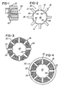
- FIG. 6 is a perspective view of a known internally-wound stator core 10.
- the internally-wound stator core 10 includes a number of circumferentially spaced-apart pole pieces or teeth 12 which cooperate to defined radially inwardly opening slots 14 which receive coils of wire during a stator winding operation.
- the stator core 10 can be wound in one of two known techniques, either pre-winding the wire into coils and then inserting the coils radially outwardly into the slots 14 from a central bore 16 of the stator core 10, or using a needle to thread or wind the wire around the pole pieces 12 from within the slots 14.
- a disadvantage associated with pre-winding a set of coils is that the wires that form the coils are susceptible to damage such as nicking and/or scraping the insulated coating that surrounds or encases the wires, when the coils are inserted around the pole pieces 12 and into the slots 14 from within the central bore 16. Damaged coil wires can electrically short to other coil wires thus reducing the wire turn count and causing excessive heat generation which may, inter alia, shorten the lifetime of the stator.
- a disadvantage associated with the needle winding technique is that there are limitations on the number of wire coils (the amount of wire fill) that can be wound around the pole pieces 12 because a certain amount of free space must be reserved in the slot 14 to permit the needle to enter and feed the next wire through the slot 14.
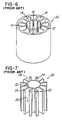
- FIG. 7 is a perspective view of a known externally-wound stator core 20 which eliminates the potential for damaging the coil wires, and eliminates the wire fill limitation associated with the internally-wound stator core 10.
- the externally-wound stator core 20 includes a thin circular member 22 defining an inner diameter of the stator core 20, and a number of circumferentially spaced-apart pole pieces or teeth 24 which are individually joined to the member 22 at the radially innermost edges thereof.
- the purpose for the member 22 is to structurally retain the pole pieces 24 in a predetermined position so that the stator core 20 can be wound with coils of wire during a stator winding operation.
- the pole pieces 24 cooperate to defined radially outwardly opening slots 26 for receiving the coils of wire which are wound around the pole pieces 24 in a manner similar to winding an armature. It should be appreciated that a winding operation for an externally-wound stator core is faster and simpler than a winding operation for an internally-wound stator core.
- the member 22 provides a continuous inner circumferential surface which does not permit abrupt changes in reluctance. Sharp magnetic transitions at the radially innermost edges of the pole pieces are required for variable reluctance motor technologies such as switched reluctance motors.
- the member 22, which is a structural feature of the stator core 20 provides a magnetic short circuit which may cause a significant amount of flux leakage when a predetermined set of coils is energized. With particular types of magnetic motors, the leakage is an acceptable consequence of the member 22.
- variable reluctance motor technologies the flux leakage is not acceptable as it directly affects torque production.
- WO 92/01325 describes a reaction cylinder for small electric motors with radially extending pole pieces joined together by a circular ring at their radially innermost end.
- US 4 761 590 discloses an electric motor with a central stator and two lateral rotors. Its pole pieces are axially oriented. The coils are supported by members joining the pole pieces, the members with the coils being oriented circumferentially.
- US 5 134 327 describes a resin-molded motor with a stator having separate pole pieces supported by a holding ring arranged laterally of the pole pieces.
- a stator lamina having a number of spaced-apart pole pieces, and a member joined to each of the pole pieces at an intermediate portion thereof.
- a stator core having a number of stator lamina joined together in a direction along a longitudinal axis wherein each of the stator lamina include a number of spaced-apart pole pieces and a member joined to each of the pole pieces at an intermediate portion thereof.
- a motor including a stator core having a plurality of stator lamina joined together in a direction along a longitudinal axis wherein the stator lamina cooperate to define a central bore extending along the longitudinal axis, and wherein each of the stator lamina include a number of spaced-apart pole pieces and a member joined to each of the pole pieces at an intermediate portion thereof.
- the motor further includes a rotor mounted to rotate within the central bore.
- a method for winding a stator core including the steps of providing a stator lamina having a number of spaced-apart pole pieces and a member joined to each of the pole pieces at an intermediate portion thereof, providing outwardly opening slots defined by adjacent pole pieces and the member, and winding a wire coil around at least one of the pole pieces so that the wire extends within at least two of the outwardly opening slots.
- stator lamina which includes a circular member which joins to an intermediate portion of each pole piece.
- the stator core 30 includes a number of separate stator lamina 32 which are laminated together in a conventional manner so as to form the stator core 30.
- the stator lamina 32 are arranged in a back-to-back configuration in a direction extending along a longitudinal axis 34.
- the stator lamina 32 are laminated together in order to reduce eddy currents in a conventional manner.
- a typical lamination thickness is approximately 0.025 inches.
- each stator lamina 32 includes a number of circumferentially spaced-apart laminated steel pole pieces 36 which are joined together by a thin circular laminated steel member or web 38 at an intermediate portion of each pole piece 36.
- the pole pieces 36 and the member 38 cooperate to define a central bore 40 which extends along the longitudinal axis 34.
- the member 38 cooperates with two circumferentially-adjacent or consecutive pole pieces 36 to define radially outwardly projecting slots 41 for receiving coils of wire as described further below.
- the pole pieces 36 each have a circumferentially-extending inner wall 44 which projects radially inwardly from the member 38 to define a flanged portion 46 of each pole piece 36.
- the inner walls 44 cooperate to define a stator core inner diameter 48.
- the member 38 is spaced radially outwardly from the stator core inner diameter 48.
- the stator lamina 32 are stamped or formed from a permeable material such as low-carbon steel or silicon steel.
- the purpose of the member 38 is to structurally retain the pole pieces 36 in a predetermined position so that the stator core 30, and more particularly, the pole pieces 36, can be externally wound with coils of wire during a stator winding operation.
- the member 38 permits the pole pieces 36 to be retained in a single rigid structure which maintains the relative positional accuracy of the pole pieces 36 during the stator winding operation.
- the stator core 30 may be externally wound with wire 50 such as a polyester-coated wire also referred to as magnet wire.
- wire 50 passes through the slots 41 in a direction along the longitudinal axis 34 and over one or more pole pieces 36. In the embodiment being described there are approximately 10-12 turns of wire 50 per pole piece 36.
- a back iron or laminated metal flux tube 52 is pressed or otherwise secured over the stator core as shown in FIG. 4. The flux tube 52 facilitates holding the pole pieces 36 in place and provides a return path for the magnetic lines of flux.
- the flux tube 52 may be formed by joining annular lamina in a back-to back configuration in a direction along the longitudinal axis 34 in a manner similar to the stator core 30.
- a rotor assembly 54 is mounted to rotate within the central bore 40 to form a variable reluctance motor 55 such as a switched reluctance motor as shown in FIG. 5.
- the rotor assembly 54 has a number of radially outwardly projecting rotor teeth 56 which facilitate the rotation of the rotor assembly 54 within the central bore 40 as discussed further below.
- the rotor assembly 54 is caused to rotate in a direction identified by the arrow 57. That is, the rotation of the rotor assembly 54 is caused by a magnetic flux gradient between the flanged end portions 46 of the pole pieces 36 and the outwardly projecting rotor teeth 56 when opposing pole pieces 36 are selectively energized by current flow through the wire coils 50.
- the sharp magnetic corners or transitions of the pole pieces 36 result in a magnetic stress tensor that causes the rotor teeth 56 to be attracted to successively leading pole pieces 36.
- the sharp magnetic transitions are essential to adequate performance in the form of torque production of the variable reluctance motor 55.
- stator core 30 could be wound in a lapped multi-pole configuration where the wire coils 50 are wound around multiple pole pieces 36 rather than a single pole piece 36. That is, the stator core 30 could have a coil span of more than one pole piece 36.
- the member 38 may be substantially circular in that each portion of the member 38 that joins together adjacent pole pieces 36 could be spaced at different radial positions relative to the remaining portions of the member 38.
- pole pieces 36 may be substantially circumferentially-spaced in that a cross-section of the stator lamina 32 could form a shape other than a circle such as a polygon.
Landscapes
- Engineering & Computer Science (AREA)
- Power Engineering (AREA)
- Iron Core Of Rotating Electric Machines (AREA)
Claims (12)
- Tôle de stator comprenant
une pluralité de pièces polaires (36) espacées les unes des autres et s'étendant en direction radiale ;
une pluralité d'éléments (38) assemblant les pièces polaires (36) adjacentes ;
les parois intérieures (44) en direction radiale desdites pièces polaires (36) définissant un alésage central (40) pour la réception d'un rotor (54) ;
les pièces polaires étant disposées pour recevoir des bobines orientées en direction radiale ;
caractérisé en ce que lesdits éléments (38) sont assemblés aux dites pièces polaires (36) au niveau d'une position radiale espacée des parois intérieures (44). - Tôle de stator selon la revendication 1, sur laquelle chacune desdites pièces polaires (36) inclut une portion à bride (46) qui se projette en direction radiale vers l'intérieur à partir desdits éléments d'assemblage (38).
- Tôle de stator selon la revendication 2, sur laquelle chacune des dites portions à bride (46) inclut ladite paroi intérieure (44) qui est espacée en direction radiale desdits éléments d'assemblage (38).
- Tôle de stator selon la revendication 3, sur laquelle lesdites parois intérieures (44) coopèrent pour définir un diamètre intérieur de la tôle de stator (32).
- Tôle de stator selon la revendication 1, sur laquelle ledit élément (38) et deux pièces polaires (36) adjacentes coopèrent pour définir une encoche (41) s'ouvrant en direction radiale vers l'extérieur pour recevoir une bobine de fil (50).
- Tôle de stator selon la revendication 1, incluant en outre huit pièces polaires (36) espacées les unes des autres de manière circonférentielle.
- Noyau de stator, caractérisée en ce qu'il comprend une pluralité de tôles de stator (32) selon une des revendications 1 à 6, qui sont assemblées dans une direction le long de l'axe longitudinal de l'alésage central (40).
- Noyau de stator selon la revendication 7, incluant en outre une pluralité de bobines de fil (50) enroulées autour d'au moins une de ladite pluralité de pièces polaires (36).
- Noyau de stator selon la revendication 8, incluant en outre un tube de flux (52) entourant ladite pluralité de tôles de stator (32).
- Moteur caractérisé en ce qu'il comprend un noyau de stator selon les revendications 8 ou 9, ladite pluralité de tôles de stator (32) coopérant pour définir un alésage central (40) s'étendant le long dudit axe longitudinal (34) et un rotor (54) monté pour tourner à l'intérieur dudit alésage central (40).
- Moteur selon la revendication 10, le moteur étant un moteur à réluctance variable.
- Moteur selon la revendication 11, ledit moteur à réluctance variable étant un moteur à réluctance commutée.
Applications Claiming Priority (3)
| Application Number | Priority Date | Filing Date | Title |
|---|---|---|---|
| US08/590,274 US6304018B1 (en) | 1995-11-21 | 1995-11-21 | Externally-wound stator with improved magnetic transition |
| US590274 | 1995-11-21 | ||
| PCT/US1996/019727 WO1997019506A1 (fr) | 1995-11-21 | 1996-11-20 | Stator a enroulement externe avec transition magnetique amrlioree |
Publications (2)
| Publication Number | Publication Date |
|---|---|
| EP0862809A1 EP0862809A1 (fr) | 1998-09-09 |
| EP0862809B1 true EP0862809B1 (fr) | 2002-07-31 |
Family
ID=24361591
Family Applications (1)
| Application Number | Title | Priority Date | Filing Date |
|---|---|---|---|
| EP96944313A Expired - Lifetime EP0862809B1 (fr) | 1995-11-21 | 1996-11-20 | Stator a enroulement externe avec transition magnetique amrlioree |
Country Status (4)
| Country | Link |
|---|---|
| US (1) | US6304018B1 (fr) |
| EP (1) | EP0862809B1 (fr) |
| DE (1) | DE69622740T2 (fr) |
| WO (1) | WO1997019506A1 (fr) |
Families Citing this family (29)
| Publication number | Priority date | Publication date | Assignee | Title |
|---|---|---|---|---|
| US5710005A (en) * | 1996-10-29 | 1998-01-20 | Biocode, Inc. | Analyte detection with a gradient lateral flow device |
| JP2001145286A (ja) * | 1999-11-12 | 2001-05-25 | Mitsubishi Electric Corp | 回転電機の固定子及びその製造方法 |
| US6484388B1 (en) * | 2000-08-10 | 2002-11-26 | Delphi Technologies, Inc. | Sequential roll-forming process for a stator |
| US6448685B1 (en) * | 2000-09-28 | 2002-09-10 | General Electric Company | Stator core assembly |
| DE10057123A1 (de) * | 2000-11-16 | 2002-05-23 | Alcatel Sa | Stator für einen Elektromotor |
| JP2003052139A (ja) * | 2001-08-07 | 2003-02-21 | Hitachi Ltd | 鉄心コアおよびそれを用いた回転電機、ならびにその製造方法 |
| US20030227230A1 (en) * | 2001-08-31 | 2003-12-11 | Daniel Gizaw | Exterior winding strategy for salient pole brushless motor for fuel pump application |
| US6864616B2 (en) | 2001-10-09 | 2005-03-08 | General Electric Company | Method and apparatus for forming an electric motor having stacked laminations |
| JP3762981B2 (ja) * | 2001-10-16 | 2006-04-05 | 日本サーボ株式会社 | 永久磁石式回転電機 |
| JP4038056B2 (ja) * | 2002-02-27 | 2008-01-23 | ミネベア株式会社 | 回転電機 |
| JP3744461B2 (ja) * | 2002-04-26 | 2006-02-08 | 株式会社デンソー | 回転電機のステータ |
| US7098565B2 (en) * | 2004-04-29 | 2006-08-29 | Lg Electronics Inc. | Core-coil assembly of motor and manufacturing method thereof |
| FR2879855A1 (fr) * | 2004-12-20 | 2006-06-23 | Valeo Equip Electr Moteur | Procede de fabrication de stators de machines electriques tournantes polyphasees, stators obtenus par ce procede |
| US7851966B2 (en) * | 2008-01-10 | 2010-12-14 | Rippel Wally E | Stator for electric machine with improved efficiency and thermal performance |
| US8572838B2 (en) | 2011-03-02 | 2013-11-05 | Honeywell International Inc. | Methods for fabricating high temperature electromagnetic coil assemblies |
| US9076581B2 (en) | 2012-04-30 | 2015-07-07 | Honeywell International Inc. | Method for manufacturing high temperature electromagnetic coil assemblies including brazed braided lead wires |
| JP5376028B1 (ja) * | 2012-09-19 | 2013-12-25 | 株式会社安川電機 | ステータ及び回転電機 |
| US9027228B2 (en) | 2012-11-29 | 2015-05-12 | Honeywell International Inc. | Method for manufacturing electromagnetic coil assemblies |
| US9722464B2 (en) * | 2013-03-13 | 2017-08-01 | Honeywell International Inc. | Gas turbine engine actuation systems including high temperature actuators and methods for the manufacture thereof |
| DE102014110609A1 (de) * | 2013-08-09 | 2015-02-12 | Johnson Electric S.A. | Einphasiger bürstenloser Motor |
| CN106662408B (zh) | 2014-07-25 | 2019-11-05 | 普里派尔技术有限公司 | 流体冷却型卷绕式条带结构 |
| US10756583B2 (en) | 2014-07-25 | 2020-08-25 | Enure, Inc. | Wound strip machine |
| US11255612B2 (en) | 2014-07-25 | 2022-02-22 | Enure, Inc. | Wound strip machine |
| DE102015000769A1 (de) * | 2015-01-26 | 2016-07-28 | Brose Fahrzeugteile GmbH & Co. Kommanditgesellschaft, Würzburg | Stator für einen Elektromotor sowie Verfahren zu dessen Herstellung |
| US10707716B2 (en) | 2017-11-20 | 2020-07-07 | Borgwarner Inc. | Stator core and stator slot closer |
| CN111987817B (zh) * | 2019-05-24 | 2023-11-24 | 北京金风科创风电设备有限公司 | 电机及电机的装配方法 |
| US12316176B2 (en) | 2021-11-17 | 2025-05-27 | Baker Hughes Oilfield Operations Llc | Method for external winding of ESP motor using a split core stator |
| DE102022103645A1 (de) | 2022-02-16 | 2023-08-17 | Schaeffler Technologies AG & Co. KG | Verfahren zur Herstellung einer Komponente für eine elektrische Maschine, Komponente für eine elektrische Maschine und elektrische Maschine |
| US20240055923A1 (en) * | 2022-08-12 | 2024-02-15 | Ghsp, Inc. | Synchronous reluctance motor having a stator with stacked laminations and a method of construction |
Citations (1)
| Publication number | Priority date | Publication date | Assignee | Title |
|---|---|---|---|---|
| US4761590A (en) * | 1987-07-20 | 1988-08-02 | Polestar Magnetronics Inc. | Electric motor |
Family Cites Families (29)
| Publication number | Priority date | Publication date | Assignee | Title |
|---|---|---|---|---|
| US2607816A (en) * | 1947-01-29 | 1952-08-19 | Stewart Warner Corp | Electric motor |
| US2695969A (en) * | 1950-08-31 | 1954-11-30 | Singer Mfg Co | Stator core construction for dynamoelectric machines |
| US2711008A (en) * | 1950-10-26 | 1955-06-21 | Beresford James & Son Ltd | Manufacture of stators for electric motors |
| US3477125A (en) | 1967-07-20 | 1969-11-11 | Robbins & Myers | Method of making a double insulated armature |
| DE1763506B2 (de) | 1968-06-14 | 1972-06-22 | Licentia Patent Verwaltungs GmbH, 6000 Frankfurt | Kleiner elektromotor mit geschlossenen staendernuten |
| US3489938A (en) | 1969-01-13 | 1970-01-13 | Kinzo Nakamura | Coil retainer for an iron core of rotary machines of the laminated iron core type |
| US3827141A (en) * | 1972-05-17 | 1974-08-06 | Skf Ind Trading & Dev | Method of manufacturing an electric rotary machine |
| JPS4954801A (fr) | 1972-09-27 | 1974-05-28 | ||
| US3914859A (en) * | 1974-01-17 | 1975-10-28 | Ray T Pierson | Method of fabricating closed slot stator construction particularly adapted for stepper motors |
| US4025840A (en) | 1975-04-09 | 1977-05-24 | General Electric Company | Permanent magnet generator with output power adjustment by means of magnetic shims |
| US4080724A (en) | 1976-01-13 | 1978-03-28 | Zephyr Wind Dynamo Company | Method of forming electrical machine care from E-laminations |
| DE2659384C2 (de) | 1976-12-29 | 1982-04-08 | Siemens AG, 1000 Berlin und 8000 München | Ständer für einen Mehrphasen-Elektromotor |
| JPS60160358A (ja) | 1984-01-27 | 1985-08-21 | Tamagawa Seiki Kk | ブラシレス直流モ−タ− |
| US4563808A (en) | 1984-07-20 | 1986-01-14 | Edo Corporation | Methods of producing slotless and toothless wound stator |
| US5173651A (en) | 1985-06-28 | 1992-12-22 | Kollmorgen Technologies Corporation | Electrical drive systems |
| US4937485A (en) | 1986-09-22 | 1990-06-26 | Hhk, Inc. | Coil/magnet structure for a brushless DC motor |
| US4780635A (en) | 1987-02-27 | 1988-10-25 | General Electric Company | Dynamo-electric machine lamination construction |
| JPH0191628A (ja) * | 1987-10-02 | 1989-04-11 | Matsushita Electric Ind Co Ltd | 固定子 |
| US4801832A (en) | 1987-11-04 | 1989-01-31 | General Electric Company | Stator and rotor lamination construction for a dynamo-electric machine |
| JP2844610B2 (ja) * | 1988-09-14 | 1999-01-06 | 松下電器産業株式会社 | モールドモータ |
| US5173629A (en) | 1989-11-13 | 1992-12-22 | A. O. Smith Corporation | Electric motor stator assembly with square edged stator plates |
| US5086245A (en) | 1990-03-06 | 1992-02-04 | S1 Montevideo Technology, Inc. | Brushless DC motor slotted tooth lamination |
| DE9010318U1 (de) | 1990-07-07 | 1991-11-07 | Robert Bosch Gmbh, 70469 Stuttgart | Rückschlußzylinder für elektrische Kleinmotoren |
| US5111096A (en) * | 1991-03-15 | 1992-05-05 | Emerson Electric Co. | Isolated segmental switch reluctance motor |
| JPH04344137A (ja) * | 1991-05-20 | 1992-11-30 | Sanyo Electric Co Ltd | 電動機の固定子及び固定子の製造方法 |
| JP2667073B2 (ja) | 1991-10-22 | 1997-10-22 | 株式会社東芝 | スロットレスモータ |
| US5382860A (en) | 1992-02-18 | 1995-01-17 | General Electric Company | Electromagnetic pump stator core |
| US5349741A (en) | 1992-06-24 | 1994-09-27 | L.H. Carbide Corporation | Method of making an interlocked core spaced for anneal penetration |
| US5306976A (en) | 1993-01-29 | 1994-04-26 | General Electric Company | Motor and stationary assembly therefor having end caps and overlapping film slot insulation |
-
1995
- 1995-11-21 US US08/590,274 patent/US6304018B1/en not_active Expired - Fee Related
-
1996
- 1996-11-20 DE DE69622740T patent/DE69622740T2/de not_active Expired - Fee Related
- 1996-11-20 WO PCT/US1996/019727 patent/WO1997019506A1/fr not_active Ceased
- 1996-11-20 EP EP96944313A patent/EP0862809B1/fr not_active Expired - Lifetime
Patent Citations (1)
| Publication number | Priority date | Publication date | Assignee | Title |
|---|---|---|---|---|
| US4761590A (en) * | 1987-07-20 | 1988-08-02 | Polestar Magnetronics Inc. | Electric motor |
Also Published As
| Publication number | Publication date |
|---|---|
| US6304018B1 (en) | 2001-10-16 |
| EP0862809A1 (fr) | 1998-09-09 |
| DE69622740T2 (de) | 2003-03-13 |
| WO1997019506A1 (fr) | 1997-05-29 |
| DE69622740D1 (de) | 2002-09-05 |
Similar Documents
| Publication | Publication Date | Title |
|---|---|---|
| EP0862809B1 (fr) | Stator a enroulement externe avec transition magnetique amrlioree | |
| US6806615B2 (en) | Core, rotating machine using the core and production method thereof | |
| US6107718A (en) | Stator for an electrical machine | |
| US6313559B1 (en) | Stator arrangement of rotary electric machine | |
| EP0740397B1 (fr) | Structure pour un stator de machine électrique tournante | |
| EP1575146B1 (fr) | Noyau composite de poudre magnétiquement doux | |
| US20040207284A1 (en) | Stator assembly including a core slot insert member | |
| US6194806B1 (en) | Compact cylindrical radial gap type motor | |
| EP1024579A3 (fr) | Alternateur | |
| EP2680412B1 (fr) | Agencement de fils de bobine dans un rotor de moteur électrique | |
| US20020093269A1 (en) | Slot area undercut for segmented stators | |
| JP2000041367A (ja) | ハイブリッド励磁形同期機 | |
| US7227291B2 (en) | Stator for an electrical machine | |
| EP3867997B1 (fr) | Structure et technologie de machine électrique | |
| EP1122858A3 (fr) | Alternateur pour véhicule automobile | |
| US20200287435A1 (en) | Electric machine | |
| US5317227A (en) | Rotor with hollow cylindrical permanent magnet | |
| EP3048704B1 (fr) | Stator de machine électrique rotative | |
| JP2024057100A (ja) | ロータの製造装置、ロータの製造方法及びロータ | |
| JPH08163803A (ja) | 永久磁石同期電動機 | |
| JP2000245120A (ja) | 回転電機のコイル組立体およびその製造方法 | |
| JPH033625A (ja) | 電機子組立体 | |
| US5328108A (en) | Method for winding coils on a Y-connection armature for miniature motors | |
| JP2000092795A (ja) | 回転電機用固定子の製造方法 | |
| KR20020081385A (ko) | 전기 기계의 회전자 또는 고정자용 부품 |
Legal Events
| Date | Code | Title | Description |
|---|---|---|---|
| PUAI | Public reference made under article 153(3) epc to a published international application that has entered the european phase |
Free format text: ORIGINAL CODE: 0009012 |
|
| 17P | Request for examination filed |
Effective date: 19980622 |
|
| AK | Designated contracting states |
Kind code of ref document: A1 Designated state(s): DE |
|
| 17Q | First examination report despatched |
Effective date: 20000420 |
|
| GRAG | Despatch of communication of intention to grant |
Free format text: ORIGINAL CODE: EPIDOS AGRA |
|
| GRAG | Despatch of communication of intention to grant |
Free format text: ORIGINAL CODE: EPIDOS AGRA |
|
| GRAH | Despatch of communication of intention to grant a patent |
Free format text: ORIGINAL CODE: EPIDOS IGRA |
|
| GRAH | Despatch of communication of intention to grant a patent |
Free format text: ORIGINAL CODE: EPIDOS IGRA |
|
| GRAA | (expected) grant |
Free format text: ORIGINAL CODE: 0009210 |
|
| AK | Designated contracting states |
Kind code of ref document: B1 Designated state(s): DE |
|
| REF | Corresponds to: |
Ref document number: 69622740 Country of ref document: DE Date of ref document: 20020905 |
|
| PLBE | No opposition filed within time limit |
Free format text: ORIGINAL CODE: 0009261 |
|
| STAA | Information on the status of an ep patent application or granted ep patent |
Free format text: STATUS: NO OPPOSITION FILED WITHIN TIME LIMIT |
|
| 26N | No opposition filed |
Effective date: 20030506 |
|
| PGFP | Annual fee paid to national office [announced via postgrant information from national office to epo] |
Ref country code: DE Payment date: 20031231 Year of fee payment: 8 |
|
| PG25 | Lapsed in a contracting state [announced via postgrant information from national office to epo] |
Ref country code: DE Free format text: LAPSE BECAUSE OF NON-PAYMENT OF DUE FEES Effective date: 20050601 |