EP0862873A1 - Ferrure pour fixation - Google Patents
Ferrure pour fixation Download PDFInfo
- Publication number
- EP0862873A1 EP0862873A1 EP98103183A EP98103183A EP0862873A1 EP 0862873 A1 EP0862873 A1 EP 0862873A1 EP 98103183 A EP98103183 A EP 98103183A EP 98103183 A EP98103183 A EP 98103183A EP 0862873 A1 EP0862873 A1 EP 0862873A1
- Authority
- EP
- European Patent Office
- Prior art keywords
- fastening fitting
- clamping part
- fitting according
- clamping
- drawer frame
- Prior art date
- Legal status (The legal status is an assumption and is not a legal conclusion. Google has not performed a legal analysis and makes no representation as to the accuracy of the status listed.)
- Granted
Links
- 238000004873 anchoring Methods 0.000 claims abstract description 40
- 229910000639 Spring steel Inorganic materials 0.000 claims description 3
- 239000002184 metal Substances 0.000 claims description 2
- 238000010586 diagram Methods 0.000 description 18
- 229910000831 Steel Inorganic materials 0.000 description 1
- 238000006073 displacement reaction Methods 0.000 description 1
- 238000009434 installation Methods 0.000 description 1
- 239000010959 steel Substances 0.000 description 1
- 230000007704 transition Effects 0.000 description 1
Images








Classifications
-
- A—HUMAN NECESSITIES
- A47—FURNITURE; DOMESTIC ARTICLES OR APPLIANCES; COFFEE MILLS; SPICE MILLS; SUCTION CLEANERS IN GENERAL
- A47B—TABLES; DESKS; OFFICE FURNITURE; CABINETS; DRAWERS; GENERAL DETAILS OF FURNITURE
- A47B88/00—Drawers for tables, cabinets or like furniture; Guides for drawers
- A47B88/90—Constructional details of drawers
- A47B88/944—Drawers characterised by the front panel
- A47B88/95—Drawers characterised by the front panel characterised by connection means for the front panel
-
- A—HUMAN NECESSITIES
- A47—FURNITURE; DOMESTIC ARTICLES OR APPLIANCES; COFFEE MILLS; SPICE MILLS; SUCTION CLEANERS IN GENERAL
- A47B—TABLES; DESKS; OFFICE FURNITURE; CABINETS; DRAWERS; GENERAL DETAILS OF FURNITURE
- A47B88/00—Drawers for tables, cabinets or like furniture; Guides for drawers
- A47B88/90—Constructional details of drawers
- A47B88/944—Drawers characterised by the front panel
- A47B88/95—Drawers characterised by the front panel characterised by connection means for the front panel
- A47B2088/953—Drawers characterised by the front panel characterised by connection means for the front panel fastening the front panel to a metal sheet side wall
-
- A—HUMAN NECESSITIES
- A47—FURNITURE; DOMESTIC ARTICLES OR APPLIANCES; COFFEE MILLS; SPICE MILLS; SUCTION CLEANERS IN GENERAL
- A47B—TABLES; DESKS; OFFICE FURNITURE; CABINETS; DRAWERS; GENERAL DETAILS OF FURNITURE
- A47B88/00—Drawers for tables, cabinets or like furniture; Guides for drawers
- A47B88/90—Constructional details of drawers
- A47B88/944—Drawers characterised by the front panel
- A47B88/95—Drawers characterised by the front panel characterised by connection means for the front panel
- A47B2088/954—Drawers characterised by the front panel characterised by connection means for the front panel fastening the front panel by a sprung bolt, latch or lock-bolt
-
- A—HUMAN NECESSITIES
- A47—FURNITURE; DOMESTIC ARTICLES OR APPLIANCES; COFFEE MILLS; SPICE MILLS; SUCTION CLEANERS IN GENERAL
- A47B—TABLES; DESKS; OFFICE FURNITURE; CABINETS; DRAWERS; GENERAL DETAILS OF FURNITURE
- A47B88/00—Drawers for tables, cabinets or like furniture; Guides for drawers
- A47B88/90—Constructional details of drawers
- A47B88/944—Drawers characterised by the front panel
- A47B88/95—Drawers characterised by the front panel characterised by connection means for the front panel
- A47B2088/955—Drawers characterised by the front panel characterised by connection means for the front panel fastening the front panel using a toggle-lever
Definitions
- the invention relates to a fastening fitting with a clamping part for fastening a front panel of a drawer on metallic drawer frames, preferably are designed as pull-out rails of a drawer extension, with a vertical web that forms the side wall of the drawer, being in each drawer frame an opening, preferably a vertical slot, is provided in the vertical web into which a lateral projection of the clamping part protrudes, and the mounting bracket an angular Fitting part with a mounting plate aligned parallel to the front panel and an anchoring plate aligned perpendicular to the front panel, in which preferably an eccentric for the height adjustment of the mounting bracket.
- Such a mounting bracket is known for example from AT 387 316 B. He enables quick anchoring of the front panel to the drawer frames, whereby however, an alignment of the front panel with respect to the drawer frames is possible. Only when the front panel is correctly positioned are the clamping parts of the mounting bracket clamped together and the front panel in relation to the drawer frames fixed.
- the mounting bracket has a holding part which can be inserted into the drawer frame and which carries the front panel, and a separate toggle mechanism with a clamping part, by means of which the holding part can be anchored within the drawer frame.
- the object of the invention is to improve such a mounting fitting in that that a tool-free assembly and disassembly of the front panel is possible, whereby the mounting bracket should be used especially with single-walled frames.
- the aim is to correct the position of the front panel in relation to the drawer frames to be possible.
- the object of the invention is achieved in that on the anchor plate Tension lever is pivotally mounted by means of an axis, with which the on the anchoring plate slidably mounted clamping part in the clamping position and thus its lateral projection is movable into the opening in the drawer frame.
- Another object of the invention is to ensure that the front panel can only be clamped with the drawer frames if the mounting bracket has taken the correct position on the drawer frame.
- this is achieved in that at least one stop is provided on the tensioning lever, which tilts the tensioning lever in the clamping position when the mounting bracket is incorrectly positioned on the drawer frame prevented.
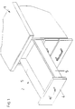
- drawers 2 are arranged, in which the front panel 4 by means of the invention Fastening fittings 3 is anchored to the drawer frames 5.
- the drawer frames 5 are made of metal, in particular sheet steel, and have on them upper edge in a conventional manner on a catwalk for a body-side roller. At the rear, the drawer frames 5 are each provided with a roller on one side of the body Carrier rail expires. The drawer bottom and the drawer back are connected in a conventional manner to the drawer frames 5.
- Each drawer frame 5 is provided at the front with a recess 6 which is open towards the front.
- the recess 6 has a vertically projecting nose 18 at the bottom, so that the fastening fitting 3 for example with an eccentric 13 for height adjustment in the Drawer frame 5 can be hung.
- This is the front panel 4 on the drawer frames 5 held, but is still adjustable in terms of their exact position.
- the front panel 4 is permanently positioned on the respective drawer frame 5.
- a vertical slot 7 which forms the opening into the the lateral projection 16 of the clamping part 11 protrudes.
- the fastening fitting 3 has an alignment parallel to the front panel 4 Mounting plate 9, which can be screwed to the front panel 4, and one Anchoring plate 8 aligned perpendicular to the front panel 4.
- the fastening plate 8 has horizontal elongated holes 32, which allow a lateral adjustment of the front panel 4.
- the tensioning lever 10 is on the anchoring plate 8 by means of an in the anchoring plate 8 stored bolt-shaped anchoring part 12 stored.
- the tension lever 10 is about an axis, which is formed by a bolt 14, around the anchoring part 12 tiltable.
- the anchoring part 12 is riveted into the anchoring plate 8.
- the plate-shaped is located between the tensioning lever 10 and the anchoring plate 8 trained clamping part 11.
- the clamping part 11 has on its on the mounting plate 9 adjacent edge on an angled web 19, with which it is between the mounting plate 9 and a projection 33 of the anchoring plate 8 is guided. By tipping of the clamping lever 10, the plate-shaped clamping part 11 is moved.
- the tension lever 10, which is supported on the bolt 14, has a nose 17, with which it rests on the clamping part 11 presses and thus moves it.
- the tensioning lever 10 is also provided with a recess 21 provided within which the clamping part 11 is received in the clamping position.
- the plate-shaped Clamping part 11 is also by the bolt-shaped anchoring part 12, the protrudes through a hole of the clamping part 11.
- the lateral projection 16 of the clamping part 11 is wedge-shaped and presses with one Inclined surface 16 'on a corresponding inclined surface 7' of the vertical slot 7, whereby the clamping part 11 and thus the mounting bracket 3 with the front panel 4 Drawer frame 5 is pulled.
- the anchoring plate 8 is provided with a recess 22 into which the lateral projection 16 of the clamping part 11 projects in the clamping position.
- the anchoring plate 8 is designed as a double plate with a outer plate 8 'and an inner plate 8' ', these plates 8', 8 '' in mounting position between them take up the vertical web of the drawer frame 5.
- Sockets 22 are formed on the inner plate 8 ′′, on which levers 23 are articulated by means of bolts 24 are.
- the levers 23 are also rotatably connected to the tensioning lever 10 via bolts 25.
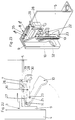
- the clamping lever 10 is connected to the clamping part 20 by means of a bolt 14.
- the bolt 14 projects through a slot 27 in a guide block 28 which is on the anchoring plate 8, namely on the inner plate 8 ''.
- the slot 27 is vertical aligned to the mounting plate 9 and thus to the front panel 4.
- the clamping part 20 is in a further slot 30 of the guide block via a second bolt 29 28 stored.
- the slot 30 is oblique to the drawer frame 5 and the front panel 4 aligned. However, it has one at its end facing the front panel 4 angled neck 31, which lies on a straight line with the slot 27 and to the front panel 4 shows.
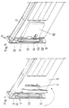
- the mounting of the mounting bracket 3 on the drawer frame 5 is particularly in 16 to 19 shown.
- the mounting bracket 3 which is screwed to the front panel 4, on the inserted the front end of the drawer frame 5, the eccentric 13 for the height adjustment is located within the recess 6 and behind the nose 18.
- the clamping part 20 is U-shaped in cross section and comprises the guide block 28 with its two side legs 20 ', which ensures stable guidance of the clamping part 20 is guaranteed.
- the anchoring part 12 is bow-shaped and is inserted with its side webs through the slots 35 in the anchor plate 8 and connected to the tensioning lever 10 via the bolt 14.
- the anchoring part 12 instructs its central web has a cylindrical projection 40, which in a hole 36 in the anchor plate 8 protrudes.
- the projection 40 can be riveted to the anchoring plate 8.
- the separate anchoring part 12 makes it possible to have different tension levers 10 and to connect clamping parts 11 to the anchoring plate 8.
- the clamping part 11 is preferably made of spring steel.
- the clamping part 11 has on its on the mounting plate 9 adjacent edge on an angled web 19, which with two guide tabs 34th is provided with which the clamping part 11 is guided in the anchoring plate 8.
- the guide tab 34 protrude through slots 37 in the anchoring plate 8.
- the control part 120 with a U-shaped cross section is attached to the tensioning lever 10. He can with the tension lever 10 be riveted.
- the control part 120 has in the exemplary embodiment shown two side webs 121, 122.
- a cam 38 is formed on each of the two side webs 121, 122.
- the mounting bracket 3 on the drawer frame 5 is in the correct position and the clamping lever 10 is pressed into the clamping position, then the cams 38 the control part 120, the projection 16 of the clamping part 11 in the slot 7 in the drawer frame 5.
- the hook-shaped stop 115 in the same slot 7 Drawer frame 5 moves.
- the hook-shaped stop 15 is at a distance to the front, i.e. the edge of the slot 7 facing the front panel 4 the hook-shaped stop 115 a pull-out protection when on the front panel 4 with too much force is exerted. This can be the case, for example, when the drawer 2 is pulled out of the furniture body 1 and jammed.
- the mounting bracket 3 can move against the spring pressure of the clamping part 11 so far relative to the drawer frame 5, until the hook-shaped stop 115 abuts the front edge of the slot 7.
- Advantageous is the tip of the stop 15 in the tensioned position in a recess of the anchoring plate 8 added.
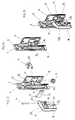
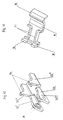
- the mounting bracket 3 When mounting the front panel 4, the mounting bracket 3 is not in the correct position, which generally means that he is not far enough on the drawer frame 5 has been pushed on, and the clamping lever 10 is pressed into the clamping position, then the hook-shaped stop 115 abuts in front of the slot 7, as shown in FIG. 38 the drawer frame 5. This prevents the clamping part 11, which with its Projection 16 is also in front of the slot 7, only on the drawer frame 5 is pressed and this clamps without engaging with its projection 16 in the slot 7. Such a lateral clamping of the drawer frame 5 could be seen on the surface lead to the assumption that the front panel 4 is on the drawer frame 5 already properly attached. Such a front panel 4 would be attached the action of a corresponding force can be removed from the drawer frame 5. Furthermore the clamping part 11 could be damaged.
- the hook-shaped stop 115 is formed only on the side web 121 of the control part 120, such a could Stop 115 can also be formed on both side webs 121, 122.
- the side webs 121, 122 are each made in two parts and consist of web sections 121 ', 121' 'and 121' ', 122' '.
- the web areas 121 ', 122' arranged closer to each other than the web areas 121 '' and 122 ''.
- the Cams 38 are formed on the web areas 121 ', 122' and the hook-shaped stops 115 on the web areas 121 ′′, 122 ′′, so that when the tensioning lever 10 is closed the clamping part 11 between the web areas 121 ′′, 122 ′′ with the hook-shaped stops 115 is included.
- the clamping part 11 can, as shown in the exemplary embodiment according to FIG. 33, as a leaf spring be trained. However, as shown in FIG. 41, it can also have edges 41 which serve to stiffen the clamping part 11.
- the cap-shaped tension lever 10 has an opening 42 in a side web with a contour to hold a tool, such as a Phillips screwdriver serves. By turning and / or tilting the Phillips screwdriver Tension lever 10 opened and the mounting bracket 3 released from the drawer frame 5 will.
- FIGS. 42 to 44 can, as shown in FIGS. 42 to 44, on the inside of the anchor plate 8 Be spring element 43 attached.
- the spring element 43 of a plastic block is formed, on which a resilient tab 44 is formed.
- the resilient tab 44 is supported on the clamping part 11 and presses it into the release position, so that the drawer frame 5 easily between the anchoring plate 8 and the clamping part 11 can be inserted.
- the spring action of the spring element 43 or resilient flap 44 so weak that it is not noticeable when the tensioning lever is tensioned.
- a leaf spring made of spring steel can also be used as the spring element be used.
Landscapes
- Drawers Of Furniture (AREA)
- Clamps And Clips (AREA)
- Connection Of Plates (AREA)
- Furniture Connections (AREA)
- Straightening Metal Sheet-Like Bodies (AREA)
Applications Claiming Priority (6)
| Application Number | Priority Date | Filing Date | Title |
|---|---|---|---|
| AT0035797A AT405896B (de) | 1997-03-03 | 1997-03-03 | Befestigungsbeschlag |
| AT35797 | 1997-03-03 | ||
| AT357/97 | 1997-03-03 | ||
| AT200997 | 1997-11-27 | ||
| AT200997A AT407334B (de) | 1997-11-27 | 1997-11-27 | Befestigungsbeschlag |
| AT2009/97 | 1997-11-27 |
Publications (2)
| Publication Number | Publication Date |
|---|---|
| EP0862873A1 true EP0862873A1 (fr) | 1998-09-09 |
| EP0862873B1 EP0862873B1 (fr) | 2001-10-31 |
Family
ID=25592447
Family Applications (1)
| Application Number | Title | Priority Date | Filing Date |
|---|---|---|---|
| EP98103183A Expired - Lifetime EP0862873B1 (fr) | 1997-03-03 | 1998-02-24 | Ferrure pour fixation et tiroir pour une telle ferrure |
Country Status (8)
| Country | Link |
|---|---|
| US (1) | US6179399B1 (fr) |
| EP (1) | EP0862873B1 (fr) |
| JP (1) | JP3513611B2 (fr) |
| CN (1) | CN1108127C (fr) |
| AT (1) | ATE207718T1 (fr) |
| AU (1) | AU726154B2 (fr) |
| DE (1) | DE59801908D1 (fr) |
| ES (1) | ES2163214T3 (fr) |
Cited By (3)
| Publication number | Priority date | Publication date | Assignee | Title |
|---|---|---|---|---|
| WO2008010036A1 (fr) * | 2006-07-14 | 2008-01-24 | Harn Marketing Sdn. Bhd. | Raccord de tiroir |
| US7429090B2 (en) | 2003-07-21 | 2008-09-30 | Arturo Salice, Spa | Attachment device for drawer front panels |
| DE202011109565U1 (de) * | 2011-12-23 | 2013-03-25 | Grass Gmbh | Vorrichtung zur Anbindung eines Möbelauszugs an einer Möbelfront |
Families Citing this family (27)
| Publication number | Priority date | Publication date | Assignee | Title |
|---|---|---|---|---|
| US20030160552A1 (en) * | 2002-02-22 | 2003-08-28 | Bacho Brett W. | Stress relieving plate |
| MY135151A (en) * | 2002-05-17 | 2008-02-29 | Harn Marketing Sdn Bhd | Drawer fitting arrangement |
| GB2401305B (en) * | 2003-05-09 | 2006-03-01 | Window Fab & Fixing Supplies | Fixing device |
| CN100405955C (zh) * | 2004-02-23 | 2008-07-30 | 川湖工厂股份有限公司 | 抽屉侧板与面板的结合装置 |
| US7207637B2 (en) * | 2004-04-07 | 2007-04-24 | King Slide Works Co., Ltd. | Coupling apparatus for a side panel and a face panel of drawers |
| DE202005001281U1 (de) * | 2005-01-27 | 2005-03-31 | Hettich Paul Gmbh & Co Kg | Schubkasten mit zwei Seitenzargen und einer Blende |
| DE202005001282U1 (de) * | 2005-01-27 | 2005-03-31 | Hettich Paul Gmbh & Co Kg | Schubkasten |
| DE202005001283U1 (de) * | 2005-01-27 | 2005-03-31 | Hettich Paul Gmbh & Co Kg | Schubkasten mit zwei Seitenzargen und mit einer Blende |
| AT505432B1 (de) * | 2007-07-11 | 2012-08-15 | Blum Gmbh Julius | Schubladenzarge mit einer befestigungseinrichtung für eine frontblende |
| DE202009004982U1 (de) * | 2009-07-02 | 2010-11-25 | Paul Hettich Gmbh & Co. Kg | Schubkasten |
| DE202010002617U1 (de) | 2010-02-22 | 2010-09-02 | Inter Ikea Systems B.V. | Befestigungssystem |
| US8585162B2 (en) * | 2010-09-20 | 2013-11-19 | Tayde Pantoja | Recessed storage compartment |
| USD659448S1 (en) * | 2010-12-22 | 2012-05-15 | Belwith Products, Llc | Removable drawer front panel for display bin |
| USD660057S1 (en) * | 2010-12-22 | 2012-05-22 | Belwith Products, Llc | Removable drawer front panel for display bin |
| USD659447S1 (en) * | 2010-12-22 | 2012-05-15 | Belwith Products, Llc | Removable drawer front panel for display bin |
| US9133651B2 (en) * | 2012-09-28 | 2015-09-15 | Albert Long Trinh | Furniture drawer locking device |
| DE202014008003U1 (de) * | 2014-10-02 | 2016-01-05 | Grass Gmbh | Blendenprofilabdeckvorrichtung |
| CN104802458B (zh) * | 2015-04-15 | 2017-11-24 | 广东万联包装机械有限公司 | 瓦楞机挡浆快速拆卸机构 |
| JP2018140645A (ja) * | 2017-02-24 | 2018-09-13 | 本田技研工業株式会社 | リーフスプリングのブラケット構造 |
| DE102018105316A1 (de) * | 2018-03-08 | 2019-09-12 | Wincor Nixdorf International Gmbh | Anordnung mit einem in einem Gehäuse angeordneten Kartenleser |
| CN108547835B (zh) * | 2018-04-03 | 2024-06-07 | 福建龙净高精设备制造有限公司 | 板件锁紧装置 |
| CN108775312B (zh) * | 2018-05-25 | 2024-04-19 | 成都纵横大鹏无人机科技有限公司 | 一种快拆自锁紧结构 |
| TWI679352B (zh) * | 2018-11-07 | 2019-12-11 | 英業達股份有限公司 | 扣合裝置 |
| WO2020118286A1 (fr) | 2018-12-07 | 2020-06-11 | Albert Long Trinh | Dispositif de fixation de tiroir de meuble |
| CN112112871A (zh) * | 2019-06-19 | 2020-12-22 | 鸿富锦精密工业(武汉)有限公司 | 浮动连接机构及连接组件 |
| TWI712381B (zh) * | 2020-02-25 | 2020-12-11 | 川湖科技股份有限公司 | 用於傢俱組件的安裝裝置與安裝方法 |
| CN116123806B (zh) * | 2021-11-15 | 2025-05-13 | 青岛海尔电冰箱有限公司 | 一种用于冰箱的抽屉组件以及冰箱 |
Citations (2)
| Publication number | Priority date | Publication date | Assignee | Title |
|---|---|---|---|---|
| AT387316B (de) * | 1987-02-16 | 1989-01-10 | Blum Gmbh Julius | Aus mehreren teilen zusammensetzbare schublade |
| EP0732069A2 (fr) * | 1995-03-04 | 1996-09-18 | Hans-Werner Düpree & Co. KG. | Tiroir |
Family Cites Families (8)
| Publication number | Priority date | Publication date | Assignee | Title |
|---|---|---|---|---|
| US2775501A (en) * | 1952-08-11 | 1956-12-25 | Kyllo Herman | Tiltable front drawer panel |
| DE3713254A1 (de) * | 1986-05-14 | 1987-11-19 | Blum Gmbh Julius | Schublade |
| AT391409B (de) * | 1987-05-04 | 1990-10-10 | Blum Gmbh Julius | Vorrichtung zur befestigung einer frontblende an metallischen schubladenzargen |
| DE9213683U1 (de) * | 1992-10-12 | 1993-02-25 | Grass AG, Höchst, Vorarlberg | Frontverstellung einer Frontblende mit Aufschnappmechanik für eine Schublade |
| AT402596B (de) * | 1994-08-26 | 1997-06-25 | Blum Gmbh Julius | Möbelbeschlag, insbesondere verbindungsbeschlag möbelbeschlag, insbesondere verbindungsbeschlag |
| DE19531698B4 (de) * | 1995-08-29 | 2005-08-11 | MEPLA-WERKE LAUTENSCHLäGER GMBH & CO. KG | Halterungs-Beschlag für Frontblenden von Schubladen |
| AT405360B (de) * | 1995-09-07 | 1999-07-26 | Alfit Ag | Vorrichtung zur einstellbaren befestigung der frontblende einer schublade an deren zargen |
| AT404666B (de) | 1995-10-30 | 1999-01-25 | Blum Gmbh Julius | Schublade |
-
1998
- 1998-02-24 DE DE59801908T patent/DE59801908D1/de not_active Expired - Lifetime
- 1998-02-24 ES ES98103183T patent/ES2163214T3/es not_active Expired - Lifetime
- 1998-02-24 EP EP98103183A patent/EP0862873B1/fr not_active Expired - Lifetime
- 1998-02-24 AT AT98103183T patent/ATE207718T1/de active
- 1998-02-27 JP JP04776398A patent/JP3513611B2/ja not_active Expired - Fee Related
- 1998-03-02 CN CN98107713A patent/CN1108127C/zh not_active Expired - Lifetime
- 1998-03-03 US US09/033,719 patent/US6179399B1/en not_active Expired - Lifetime
- 1998-03-03 AU AU57381/98A patent/AU726154B2/en not_active Expired
Patent Citations (2)
| Publication number | Priority date | Publication date | Assignee | Title |
|---|---|---|---|---|
| AT387316B (de) * | 1987-02-16 | 1989-01-10 | Blum Gmbh Julius | Aus mehreren teilen zusammensetzbare schublade |
| EP0732069A2 (fr) * | 1995-03-04 | 1996-09-18 | Hans-Werner Düpree & Co. KG. | Tiroir |
Cited By (4)
| Publication number | Priority date | Publication date | Assignee | Title |
|---|---|---|---|---|
| US7429090B2 (en) | 2003-07-21 | 2008-09-30 | Arturo Salice, Spa | Attachment device for drawer front panels |
| WO2008010036A1 (fr) * | 2006-07-14 | 2008-01-24 | Harn Marketing Sdn. Bhd. | Raccord de tiroir |
| US8262175B2 (en) | 2006-07-14 | 2012-09-11 | Harn Marketing Sdn. Bhd. | Drawer fitting |
| DE202011109565U1 (de) * | 2011-12-23 | 2013-03-25 | Grass Gmbh | Vorrichtung zur Anbindung eines Möbelauszugs an einer Möbelfront |
Also Published As
| Publication number | Publication date |
|---|---|
| EP0862873B1 (fr) | 2001-10-31 |
| AU5738198A (en) | 1998-09-03 |
| ES2163214T3 (es) | 2002-01-16 |
| DE59801908D1 (de) | 2001-12-06 |
| CN1202582A (zh) | 1998-12-23 |
| JPH10281120A (ja) | 1998-10-20 |
| AU726154B2 (en) | 2000-11-02 |
| ATE207718T1 (de) | 2001-11-15 |
| JP3513611B2 (ja) | 2004-03-31 |
| US6179399B1 (en) | 2001-01-30 |
| CN1108127C (zh) | 2003-05-14 |
Similar Documents
| Publication | Publication Date | Title |
|---|---|---|
| EP0862873B1 (fr) | Ferrure pour fixation et tiroir pour une telle ferrure | |
| EP1147725B1 (fr) | Guide de sortie pour tiroirs | |
| EP0289866B1 (fr) | Dispositif de fixation d'une plaque frontale à un cadre de tiroir métallique | |
| AT391407B (de) | Befestigungsvorrichtung fuer einstellbare frontblenden von schubladen | |
| EP0160733B1 (fr) | Tiroir de meuble | |
| DE3713254A1 (de) | Schublade | |
| DE3620450C2 (fr) | ||
| DE9421872U1 (de) | Vorrichtung zur Befestigung der Frontblende einer Schublade an Schubladenzargen | |
| EP0664984A2 (fr) | Coulisse de tiroir séquentielle ou similaire | |
| EP0740917A1 (fr) | Dispositif pour fixer le panneau avant de tiroir, en particulier tiroir à double paroi, sur les parois latérales | |
| AT398516B (de) | Schubkastenauszug | |
| EP0633367A1 (fr) | Coffrage avec panneaux de coffrage et dispositifs d'assemblage | |
| EP0030290A2 (fr) | Tiroir | |
| EP2479365A1 (fr) | Rail de guidage pour portes coulissantes ou repliables en accordéon | |
| EP0539672B1 (fr) | Ferrure pour fixation dans une rainure d'un profilé rétréci des deux côtés | |
| DE3643312C2 (de) | Schubkastenseitenzarge mit vorderendiger Dübelbrücke | |
| EP1841342A1 (fr) | Tiroir presentant deux parois laterales et une façade | |
| AT407334B (de) | Befestigungsbeschlag | |
| EP1243212B1 (fr) | Cloison de douche | |
| EP2233039A2 (fr) | Guidage pour tiroirs | |
| DE2131852C3 (de) | Klappenscharnier | |
| DE4336141C2 (de) | Montagevorrichtung für eine an einer Arbeits- oder Tischplatte anbaubare Trageinrichtung, insbesondere eine Monitor-Trageinrichtung bzw. Monitor-Schwenkarm | |
| EP0510346B1 (fr) | Ferrure pour la fixation d'un panneau frontal | |
| AT528665B1 (de) | Befestigungsvorrichtung zur Befestigung eines Schubladenelements an einer Schubladenseitenzarge | |
| DE3743701A1 (de) | Konsolanker |
Legal Events
| Date | Code | Title | Description |
|---|---|---|---|
| PUAI | Public reference made under article 153(3) epc to a published international application that has entered the european phase |
Free format text: ORIGINAL CODE: 0009012 |
|
| AK | Designated contracting states |
Kind code of ref document: A1 Designated state(s): AT DE ES FR GB IT |
|
| AX | Request for extension of the european patent |
Free format text: AL;LT;LV;MK;RO;SI |
|
| 17P | Request for examination filed |
Effective date: 19980716 |
|
| AKX | Designation fees paid |
Free format text: AT DE ES FR GB IT |
|
| RBV | Designated contracting states (corrected) |
Designated state(s): AT DE ES FR GB IT |
|
| 17Q | First examination report despatched |
Effective date: 20000712 |
|
| RTI1 | Title (correction) |
Free format text: FITTING FOR ATTACHMENT AND DRAWER WITH SUCH A FITTING |
|
| GRAG | Despatch of communication of intention to grant |
Free format text: ORIGINAL CODE: EPIDOS AGRA |
|
| RTI1 | Title (correction) |
Free format text: FITTING FOR ATTACHMENT AND DRAWER WITH SUCH A FITTING |
|
| GRAG | Despatch of communication of intention to grant |
Free format text: ORIGINAL CODE: EPIDOS AGRA |
|
| GRAH | Despatch of communication of intention to grant a patent |
Free format text: ORIGINAL CODE: EPIDOS IGRA |
|
| GRAH | Despatch of communication of intention to grant a patent |
Free format text: ORIGINAL CODE: EPIDOS IGRA |
|
| GRAA | (expected) grant |
Free format text: ORIGINAL CODE: 0009210 |
|
| AK | Designated contracting states |
Kind code of ref document: B1 Designated state(s): AT DE ES FR GB IT |
|
| PG25 | Lapsed in a contracting state [announced via postgrant information from national office to epo] |
Ref country code: GB Free format text: LAPSE BECAUSE OF FAILURE TO SUBMIT A TRANSLATION OF THE DESCRIPTION OR TO PAY THE FEE WITHIN THE PRESCRIBED TIME-LIMIT Effective date: 20011031 Ref country code: FR Free format text: LAPSE BECAUSE OF FAILURE TO SUBMIT A TRANSLATION OF THE DESCRIPTION OR TO PAY THE FEE WITHIN THE PRESCRIBED TIME-LIMIT Effective date: 20011031 |
|
| REF | Corresponds to: |
Ref document number: 207718 Country of ref document: AT Date of ref document: 20011115 Kind code of ref document: T |
|
| REF | Corresponds to: |
Ref document number: 59801908 Country of ref document: DE Date of ref document: 20011206 |
|
| REG | Reference to a national code |
Ref country code: ES Ref legal event code: FG2A Ref document number: 2163214 Country of ref document: ES Kind code of ref document: T3 |
|
| GBV | Gb: ep patent (uk) treated as always having been void in accordance with gb section 77(7)/1977 [no translation filed] |
Effective date: 20011031 |
|
| PLBE | No opposition filed within time limit |
Free format text: ORIGINAL CODE: 0009261 |
|
| STAA | Information on the status of an ep patent application or granted ep patent |
Free format text: STATUS: NO OPPOSITION FILED WITHIN TIME LIMIT |
|
| 26N | No opposition filed | ||
| PGFP | Annual fee paid to national office [announced via postgrant information from national office to epo] |
Ref country code: IT Payment date: 20160224 Year of fee payment: 19 Ref country code: ES Payment date: 20160321 Year of fee payment: 19 |
|
| PGFP | Annual fee paid to national office [announced via postgrant information from national office to epo] |
Ref country code: AT Payment date: 20160225 Year of fee payment: 19 |
|
| PGFP | Annual fee paid to national office [announced via postgrant information from national office to epo] |
Ref country code: DE Payment date: 20160502 Year of fee payment: 19 |
|
| REG | Reference to a national code |
Ref country code: DE Ref legal event code: R119 Ref document number: 59801908 Country of ref document: DE |
|
| REG | Reference to a national code |
Ref country code: AT Ref legal event code: MM01 Ref document number: 207718 Country of ref document: AT Kind code of ref document: T Effective date: 20170224 |
|
| PG25 | Lapsed in a contracting state [announced via postgrant information from national office to epo] |
Ref country code: AT Free format text: LAPSE BECAUSE OF NON-PAYMENT OF DUE FEES Effective date: 20170224 |
|
| PG25 | Lapsed in a contracting state [announced via postgrant information from national office to epo] |
Ref country code: DE Free format text: LAPSE BECAUSE OF NON-PAYMENT OF DUE FEES Effective date: 20170901 |
|
| PG25 | Lapsed in a contracting state [announced via postgrant information from national office to epo] |
Ref country code: IT Free format text: LAPSE BECAUSE OF NON-PAYMENT OF DUE FEES Effective date: 20170224 |
|
| REG | Reference to a national code |
Ref country code: ES Ref legal event code: FD2A Effective date: 20180507 |
|
| PG25 | Lapsed in a contracting state [announced via postgrant information from national office to epo] |
Ref country code: ES Free format text: LAPSE BECAUSE OF NON-PAYMENT OF DUE FEES Effective date: 20170225 |