EP0862890A1 - Pulverdosiervorrichtung - Google Patents
Pulverdosiervorrichtung Download PDFInfo
- Publication number
- EP0862890A1 EP0862890A1 EP98101197A EP98101197A EP0862890A1 EP 0862890 A1 EP0862890 A1 EP 0862890A1 EP 98101197 A EP98101197 A EP 98101197A EP 98101197 A EP98101197 A EP 98101197A EP 0862890 A1 EP0862890 A1 EP 0862890A1
- Authority
- EP
- European Patent Office
- Prior art keywords
- powder
- sieve
- dosing device
- solvent
- angle
- Prior art date
- Legal status (The legal status is an assumption and is not a legal conclusion. Google has not performed a legal analysis and makes no representation as to the accuracy of the status listed.)
- Granted
Links
- 239000000843 powder Substances 0.000 title claims abstract description 92
- 239000002904 solvent Substances 0.000 claims abstract description 17
- 239000004809 Teflon Substances 0.000 claims abstract description 8
- 229920006362 Teflon® Polymers 0.000 claims abstract description 8
- 239000004033 plastic Substances 0.000 claims abstract description 7
- 229920003023 plastic Polymers 0.000 claims abstract description 7
- 238000003860 storage Methods 0.000 claims description 6
- 238000007599 discharging Methods 0.000 claims description 2
- 238000011010 flushing procedure Methods 0.000 abstract 1
- 229920000915 polyvinyl chloride Polymers 0.000 abstract 1
- 239000004800 polyvinyl chloride Substances 0.000 abstract 1
- XLYOFNOQVPJJNP-UHFFFAOYSA-N water Substances O XLYOFNOQVPJJNP-UHFFFAOYSA-N 0.000 description 22
- 239000002184 metal Substances 0.000 description 8
- 239000000463 material Substances 0.000 description 5
- 239000002585 base Substances 0.000 description 3
- 230000015572 biosynthetic process Effects 0.000 description 3
- 230000002255 enzymatic effect Effects 0.000 description 3
- 239000004698 Polyethylene Substances 0.000 description 2
- 238000005520 cutting process Methods 0.000 description 2
- 239000003599 detergent Substances 0.000 description 2
- 239000010408 film Substances 0.000 description 2
- 238000004519 manufacturing process Methods 0.000 description 2
- 239000000203 mixture Substances 0.000 description 2
- 239000002985 plastic film Substances 0.000 description 2
- 229920006255 plastic film Polymers 0.000 description 2
- -1 polyethylene terephthalate Polymers 0.000 description 2
- 229920000139 polyethylene terephthalate Polymers 0.000 description 2
- 239000005020 polyethylene terephthalate Substances 0.000 description 2
- 230000003014 reinforcing effect Effects 0.000 description 2
- 241000237942 Conidae Species 0.000 description 1
- 102000004190 Enzymes Human genes 0.000 description 1
- 108090000790 Enzymes Proteins 0.000 description 1
- 230000006978 adaptation Effects 0.000 description 1
- 239000003513 alkali Substances 0.000 description 1
- 238000004140 cleaning Methods 0.000 description 1
- 239000002131 composite material Substances 0.000 description 1
- 238000010276 construction Methods 0.000 description 1
- 238000004851 dishwashing Methods 0.000 description 1
- 230000000694 effects Effects 0.000 description 1
- 238000005516 engineering process Methods 0.000 description 1
- 235000021184 main course Nutrition 0.000 description 1
- 238000000691 measurement method Methods 0.000 description 1
- 229920000573 polyethylene Polymers 0.000 description 1
- 239000007921 spray Substances 0.000 description 1
- 239000010409 thin film Substances 0.000 description 1
Images

Classifications
-
- A—HUMAN NECESSITIES
- A47—FURNITURE; DOMESTIC ARTICLES OR APPLIANCES; COFFEE MILLS; SPICE MILLS; SUCTION CLEANERS IN GENERAL
- A47L—DOMESTIC WASHING OR CLEANING; SUCTION CLEANERS IN GENERAL
- A47L15/00—Washing or rinsing machines for crockery or tableware
- A47L15/42—Details
- A47L15/44—Devices for adding cleaning agents; Devices for dispensing cleaning agents, rinsing aids or deodorants
- A47L15/4436—Devices for adding cleaning agents; Devices for dispensing cleaning agents, rinsing aids or deodorants in the form of a detergent solution made by gradually dissolving a powder detergent cake or a solid detergent block
-
- B—PERFORMING OPERATIONS; TRANSPORTING
- B01—PHYSICAL OR CHEMICAL PROCESSES OR APPARATUS IN GENERAL
- B01F—MIXING, e.g. DISSOLVING, EMULSIFYING OR DISPERSING
- B01F21/00—Dissolving
- B01F21/20—Dissolving using flow mixing
- B01F21/22—Dissolving using flow mixing using additional holders in conduits, containers or pools for keeping the solid material in place, e.g. supports or receptacles
Definitions
- the invention relates to a powder metering device for metering a powder in a solvent, with a powder storage container, a metering opening for discharging the powder out of the container, and with a feed device for Solvent that rinses the powder out through the metering opening.
- Such powder dosing devices are from obvious prior use known and serve primarily for dosing of powdery cleaners in commercial dishwashing systems.
- the metering opening is in the lower area of the Powder container (usually on the bottom) and is replaced by a Mesh sieve closed. The powder is used for dosing rinsed out through this mesh screen.
- the supply device for the solvent (usually Water) can either be above the mesh screen in the area the bed of powder or the mesh screen Rinse with water from below.
- the mesh size of the screen used must be less than the average grain size of the powder to prevent unwanted slipping to prevent the powder. Therefore, when dosing the powder above the sieve should at least be dissolved. A detergent cake is formed, which lightly cakes and clogs the sieve. This problem occurs particularly when the water is applied from the side of the sieve on which the powder spill rests. For a cleaning cake once made to dissolve again and to be able to meter in powder effectively, the state of the art with hot water (above 60 ° C) as Solvent work. On the one hand, this is complex, on the other hand hot water reduces or destroys the effect of enzymatic Cleaners because enzymes break down at high temperatures will.
- the invention has for its object a reliable and easy to use powder metering device to create the type mentioned above.
- the invention solves this problem in that the metering opening has a sieve, the sieve openings perpendicular to Sieve level have no clear cross section, and that Sieve from the side facing away from the powder storage container is charged with solvent.
- Sieve level refers to a flat sieve (i.e. H. when forming the sieve as a sieve plate) Main level, d. H. the level of greatest extension. If that Sieve a curved shape (for example a dome shape) has the term sieve plane the tangential plane of the Siebs at the location under consideration.
- the screen openings have no clear openings perpendicular to the screen level Cross section on. This means that the sieve has a certain Has thickness and that the screen openings, i.e. H. the passage openings through the screen, so inclined or curved run through the sieve so that the inlet opening and an associated outlet opening from the opposite Screen side do not overlap each other in such a way that this sieve opening seen perpendicular to the sieve plane has a clear cross section.
- the sieve is removed from the powder storage container opposite side (i.e. from the powder spill opposite side) with solvent.
- This type of water exposure makes it easier to dose the Powder and leads to little or no formation a powder cleaner cake over the sieve.
- the inventive design of the screen openings without thinning Cross section to the sieve level causes that when empty or almost empty powder container a water exposure of the Siebs cannot cause water to any appreciable extent splashes up through the sieve.
- the sieve is arranged in the bottom area of the powder container. If the powder container is almost empty, take its lid for the purpose Refilling powder and accidentally the Water supply device put into operation prevents the construction of the sieve according to the invention that water and thus Cleaner residues through the sieve upwards out of the container and possibly in the face of an operator inject. This security inherent in the invention is a significant advantage.
- the sieve openings are preferably inclined to the sieve plane Passage channels are formed, which are particularly preferred Through channels formed as through slots.
- inclination angle of the passageways included with the sieve plane less than or equal to the slope angle of the to be metered in Powder.
- slope angle of a powder is explained in more detail below. Basically the slope angle the smaller the free-flowing powder is, the smaller.
- the passage channels should be not too steep, d. H. the one with the sieve level included angle of inclination must not be too large, preferably not larger than the angle of repose of the powder. It is achieved that the powder spill does not or at most to a small extent by itself, d. H. without exposure to solvents, passes through the sieve.
- Passage channels (again up to the slope angle of the Powder) to be useful for rinsing through the sieve facilitate.
- Preferred areas of that included with the sieve plane The angle of inclination of the passage channels is 20 to 60 °, more preferably 30 to 45 °.
- the clear width of the passage channels is preferably larger than the average grain size of the powder to be metered in.
- the term "clear width" denotes the smallest width of the Passage channels transverse to their main course direction. At the formation of the passage channels as passage slots is the clear width the slot width in the direction of the course.
- the clear width of the passage channels is preferably 1.5 up to 2.5 times, more preferably about twice as large as that average grain size of the powder to be dosed. This training the passage channels also allow rinsing whole powder grains through the sieve. The one charged from below Water can powder the purely mechanical way rinse out, no previous dissolving is required. The Formation of an unwanted powder cake above the sieve is reduced or avoided in this way.
- the combination of the specified width with an angle of inclination of the passages equal to or is slightly smaller than the slope angle of the powder. On this way is with relatively small amounts of water or press a rinse and thus metering the Powder possible. Is the use for certain reasons higher water quantities and / or pressures desired, you can Reduce the angle of inclination of the channels so that rinsing is difficult.
- Preferred areas of the clear width of the Passage channels are, for example, 1.5 to 4 mm, preferably 2 to 3 mm.
- the described adjustment of inclination angle and lights The width of the passage channels makes it difficult to rinse out Powders that tend to cake, for example rinse with cold water and dispense.
- the invention Combination of inclination angle and clear width may also be independent of the characteristics of the main claim be used, especially when spurting out of water from the powder container by others Measures are prevented, for example an automatic Shut off the water supply when opening the lid.
- the solvent is preferably applied by means of a hollow cone or full cone nozzle, which is different from that of the powder bed facing away from the sieve.
- a hollow cone nozzle is preferred when dosing should be done with small amounts of solvent.
- the cone angle is preferably at the inclination of the sieve openings customized. It therefore corresponds to the angle of inclination Sieve openings or is at least similar to this, so that Solvent directed through the sieve openings and can also act mechanically on the powder bed.
- the screen is preferably provided with a screen opening (preferably flat) plastic plate formed.
- the Plastic plate can for example be a Teflon or PVC plate be.
- a Teflon sheet is due to its temperature resistance preferred with alkaline cleaners, with their Solution in water high temperatures can arise. Because Teflon tending to cold flow, the plate can be reinforced by ribs or bridges. With low alkali or -free cleaners (e.g. enzymatic cleaners) the plastic plate can be made of another material, for example PVC be made.
- a metal sieve is attached at a distance of 30 to 100 mm.
- the exact distance from the metal screen and metal cylinder depends on the pourability of the powder to be measured and should be slightly larger than the height of the cone.
- the powder is poured onto the metal sieve and with the help of a plastic spatula is slowly pushed through the sieve.
- the falling powder builds one on the metal cylinder Cone on. You pass powder through the sieve as long as until there is a geometrically uniform shape on the cylinder Cone has formed.
- the strainer is removed and the height of the pouring cone. From this height and the diameter of the metal cylinder can the angle of repose of the powder be calculated. It is the angle that the cone shell with the face of the metal cylinder on which the powder cone rests, includes.
- the powder metering device shown in FIG. 1 has one Powder storage container 1, whose lower part in the base 2 of the powder metering device is used.
- the powder dosing container 1 tapers downwards and points one open floor.
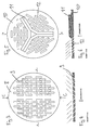
- the bottom area of the container is limited through a sieve 3 arranged in the base 2, the Design can be seen from FIGS. 3 to 6.
- Below of the sieve 3 is a cone nozzle 4 which is arranged by a Water supply line 5 is fed.
- the one in the dosing device resulting mixture or solution of powder with or in water is from the connector 6 and a dishwasher fed.
- In powder 1 is one with sharp tops provided cutting device 7 arranged.
- a PVC plate 8 is with inclined slots 9th trained passage channels provided.
- the passage channels are arranged mirror-symmetrically to the line C-C.
- Passage slots not in one half of the sieve plate 8 parallel to each other, but for example in shape of several rings concentric with each other. This arrangement in concentric rings can be due to the improved adaptation to the spray cone of the nozzle 4, the rinsability of the powder still improve.
- Fig. 5 shows a second embodiment of the sieve.
- the Sieve plate 10 here consists of Teflon. Because this material too cold flow tends, reinforcing ribs 11 are provided.
- the 3 and 4 is for dosing an enzymatic cleaner is provided, the one has average grain size of about 1 mm.
- the angle of inclination the passage slots 9 is 45 °, the inside width of the Slots 2 mm.
- the angle of repose of the powder to be dosed is 60 °, which is slightly larger than the angle of inclination Through slots.
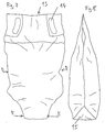
- the powder container 1 is expediently refilled with the help of a refill bag shown in FIGS. 7 and 8.
- the bag 13 consists of a plastic film, and is Provide handle openings 14 for better handling. Of the Cross section of the bag 13 tapers downwards in the direction towards the floor area 15.
- the tapered bottom of the Bag is designed as a pouring opening through a Plastic film 15 with compared to the rest of the bag material reduced strength is locked.
- the cross-sectional area of the bag in the middle area is approximately 1.5 to 3 times, preferably approximately 2 to 2.5 times the cross-sectional area in the tapered lower one Area (level E-E in Fig. 7).
- the bag 13 is gripped at the openings 14 for refilling and placed in the powder container 1.
- the cutting device 7 penetrates the bottom film 15 from the comparison to the remaining bag material softer material.
- a bottom film is, for example, a thin film of a PET / PE (polyethylene terephthalate / polyethylene) composite material suitable.
- the bag 13 is then slowly raised and empties through the slit bottom into the powder container 1.
- the tapering towards the bottom of the bag Form ensures that the bag is emptied completely. To refill the entire contents of a bag with 3 kg of content you need about 15 s. Refilling happens clean and practically dust-free, without the There is a risk of powder spillage.
- the powder in the container 1 rests on the sieve and is rinsed out if necessary by starting the nozzle 4 or dissolved and through the discharge opening 6 of the dishwasher fed.
- the base 2 of the powder metering device can still one not shown in the drawing Have overflow, then through the water / detergent mixture can emerge when the discharge opening 6 clogs once should be.
Landscapes
- Chemical & Material Sciences (AREA)
- Chemical Kinetics & Catalysis (AREA)
- Detergent Compositions (AREA)
- Processing And Handling Of Plastics And Other Materials For Molding In General (AREA)
- Nozzles (AREA)
- Catching Or Destruction (AREA)
- Sampling And Sample Adjustment (AREA)
- Washing And Drying Of Tableware (AREA)
- Agricultural Chemicals And Associated Chemicals (AREA)
Abstract
Description
- Fig. 1
- einen Längsschnitt durch eine erfindungsgemäße Pulverdosiervorrichtung;
- Fig. 2
- eine Draufsicht von oben;
- Fig. 3
- eine Draufsicht auf ein erfindungsgemäßes Sieb aus PVC;
- Fig. 4
- einen Schnitt entlang der Linie A-A in Fig. 3;
- Fig. 5
- eine Draufsicht auf ein erfindungsgemäßes Sieb aus Teflon;
- Fig. 6
- einen Schnitt entlang der Linie B-B von Fig. 5;
- Fig. 7 und 8
- zwei Ansichten eines Nachfüllbeutels für den Pulverdosierbehälter von der Seite.
Claims (11)
- Pulverdosiervorrichtung zum Eindosieren eines Pulvers in ein Lösungsmittel, mit einem Pulvervorratsbehälter (1), einer Dosieröffnung zum Abführen des Pulvers aus dem Behälter (1), und mit einer Zufuhreinrichtung (4, 5) für Lösungsmittel, das das Pulver durch die Dosieröffnung ausspült, dadurch gekennzeichnet, daß die Dosieröffnung ein Sieb (3, 8, 10) aufweist, dessen Sieböffnungen (9, 12) senkrecht zur Siebebene keinen lichten Querschnitt aufweisen, und daß das Sieb (3, 8, 10) von der dem Pulvervorratsbehälter (1) abgewandten Seite her mit Lösungsmittel beaufschlagt wird.
- Pulverdosiervorrichtung nach Anspruch 1, dadurch gekennzeichnet, daß die Sieböffnungen als zur Siebebene geneigte Durchtrittskanäle (9, 12) ausgebildet sind.
- Pulverdosiervorrichtung nach Anspruch 2, dadurch gekennzeichnet, daß die Durchtrittskanäle als Durchtrittsschlitze (9, 12) ausgebildet sind.
- Pulverdosiervorrichtung nach Anspruch 2 oder 3, dadurch gekennzeichnet, daß der mit der Siebebene eingeschlossene Neigungswinkel der Durchtrittskanäle (9, 12) kleiner oder gleich dem Böschungswinkel des einzudosierenden Pulvers ist.
- Pulverdosiervorrichtung nach einem der Ansprüche 2 bis 4, dadurch gekennzeichnet, daß der mit der Siebebene eingeschlossene Neigungswinkel der Durchtrittskanäle (9, 12) 20 bis 60°, vorzugsweise 30 bis 45° beträgt.
- Pulverdosiervorrichtung nach einem der Ansprüche 2 bis 5, dadurch gekennzeichnet, daß die lichte Weite der Durchtrittskanäle (9, 12) 1,5 bis 2,5 mal, vorzugsweise etwa doppelt so groß wie die mittlere Korngröße des einzudosierenden Pulvers ist.
- Pulverdosiervorrichtung nach einem der Ansprüche 2 bis 6, dadurch gekennzeichnet, daß die lichte Weite der Durchtrittskanäle (9, 12) 1,5 bis 4 mm, vorzugsweise 2 bis 3 mm beträgt.
- Pulverdosiervorrichtung nach einem der Ansprüche 1 bis 7, dadurch gekennzeichnet, daß die Lösungsmittelbeaufschlagung mittels einer Hohlkegel- oder Vollkegeldüse (4) erfolgt.
- Pulverdosiervorrichtung nach Anspruch 8, dadurch gekennzeichnet, daß der Kegelwinkel an die Neigung der Sieböffnungen (9, 12) angepaßt ist.
- Pulverdosiervorrichtung nach einem der Ansprüche 1 bis 9, dadurch gekennzeichnet, daß das Sieb eine mit Sieböffnungen (9, 12) versehene Kunststoffplatte (3, 8, 10) aufweist.
- Pulverdosiervorrichtung nach Anspruch 10, dadurch gekennzeichnet, daß die Kunststoffplatte eine Teflon- oder PVC-Platte (8, 10) ist.
Applications Claiming Priority (2)
| Application Number | Priority Date | Filing Date | Title |
|---|---|---|---|
| DE19709200A DE19709200A1 (de) | 1997-03-06 | 1997-03-06 | Pulverdosiervorrichtung |
| DE19709200 | 1997-03-06 |
Publications (2)
| Publication Number | Publication Date |
|---|---|
| EP0862890A1 true EP0862890A1 (de) | 1998-09-09 |
| EP0862890B1 EP0862890B1 (de) | 2002-01-09 |
Family
ID=7822460
Family Applications (1)
| Application Number | Title | Priority Date | Filing Date |
|---|---|---|---|
| EP98101197A Expired - Lifetime EP0862890B1 (de) | 1997-03-06 | 1998-01-23 | Pulverdosiervorrichtung |
Country Status (3)
| Country | Link |
|---|---|
| EP (1) | EP0862890B1 (de) |
| AT (1) | ATE211631T1 (de) |
| DE (2) | DE19709200A1 (de) |
Cited By (1)
| Publication number | Priority date | Publication date | Assignee | Title |
|---|---|---|---|---|
| DE102006007485B3 (de) * | 2006-02-17 | 2007-08-02 | Atc Establishment | Dosiervorrichtung zum Dosieren eines Pulvers |
Families Citing this family (1)
| Publication number | Priority date | Publication date | Assignee | Title |
|---|---|---|---|---|
| DE102006062910B4 (de) * | 2006-09-21 | 2014-05-08 | Witty Chemie Gmbh & Co. Kg | Vorrichtung und Verfahren zur Dosierung von Calciumhypochlorit in ein wäßriges System |
Citations (3)
| Publication number | Priority date | Publication date | Assignee | Title |
|---|---|---|---|---|
| EP0300819A2 (de) * | 1987-07-23 | 1989-01-25 | Diversey Corporation | Spender |
| US5086952A (en) * | 1988-09-12 | 1992-02-11 | Diversey Corporation | Detergent container |
| US5229084A (en) * | 1992-03-25 | 1993-07-20 | Beta Technology, Inc. | Dispenser cap with distributor for non-liquid chemical delivery systems |
-
1997
- 1997-03-06 DE DE19709200A patent/DE19709200A1/de not_active Withdrawn
-
1998
- 1998-01-23 DE DE59802593T patent/DE59802593D1/de not_active Expired - Fee Related
- 1998-01-23 AT AT98101197T patent/ATE211631T1/de not_active IP Right Cessation
- 1998-01-23 EP EP98101197A patent/EP0862890B1/de not_active Expired - Lifetime
Patent Citations (3)
| Publication number | Priority date | Publication date | Assignee | Title |
|---|---|---|---|---|
| EP0300819A2 (de) * | 1987-07-23 | 1989-01-25 | Diversey Corporation | Spender |
| US5086952A (en) * | 1988-09-12 | 1992-02-11 | Diversey Corporation | Detergent container |
| US5229084A (en) * | 1992-03-25 | 1993-07-20 | Beta Technology, Inc. | Dispenser cap with distributor for non-liquid chemical delivery systems |
Cited By (1)
| Publication number | Priority date | Publication date | Assignee | Title |
|---|---|---|---|---|
| DE102006007485B3 (de) * | 2006-02-17 | 2007-08-02 | Atc Establishment | Dosiervorrichtung zum Dosieren eines Pulvers |
Also Published As
| Publication number | Publication date |
|---|---|
| EP0862890B1 (de) | 2002-01-09 |
| DE59802593D1 (de) | 2002-02-14 |
| DE19709200A1 (de) | 1998-09-10 |
| ATE211631T1 (de) | 2002-01-15 |
Similar Documents
| Publication | Publication Date | Title |
|---|---|---|
| AT397595B (de) | Vorrichtung zur behandlung von saatgut | |
| DE3043993A1 (de) | Abgabetrichter fuer silos zum speichern von frei fliessenden feststoffen | |
| DE69306596T2 (de) | Drucktaste zum aufsetzen auf einem ventil oder einer spenderpumpe, und spender mit einer solchen drucktaste | |
| WO2011012221A1 (de) | Auftragsdüse für viskose klebstoffe | |
| DE3723588C2 (de) | ||
| EP0166017B1 (de) | Vorrichtung zum Zerlegen von Mischstoffen | |
| DE2703680B2 (de) | Auftragsvorrichtung für fließfähige, aufschäumende Reaktionsmasse | |
| EP0862890B1 (de) | Pulverdosiervorrichtung | |
| DE2744853A1 (de) | Behaelterboden zum pneumatischen austrag von feingut | |
| DE1952468C3 (de) | Zellenauslauf einer Silozelle, insbesondere für die Lagerung von Futter mittelkomponenten | |
| EP0863084B1 (de) | Kit und Nachfüllbeutel zum Eindosieren eines Pulvers | |
| DE3153697C2 (de) | ||
| DE4328071A1 (de) | Vorrichtung zur Entnahme von schwerfließenden Schüttgütern aus einem Silo | |
| DE2114640B2 (de) | Vorrichtung zum reinigen von kartoffelstueckchen | |
| AT394015B (de) | Treibgaslose schaumabgabeeinrichtung | |
| EP0168414A1 (de) | Austragsvorrichtung für einen schüttgut-behälter. | |
| DE8702580U1 (de) | Mundstück für einen Spritzbeutel | |
| DE2233126B1 (de) | Streugeraet | |
| DE7235359U (de) | Behälterboden zum pneumatischen Mischen und Austragen von Feingut | |
| DE9211730U1 (de) | Trockenbehälter zur Trocknung von Kunststoffgranulaten | |
| EP0492204A1 (de) | Behälter zum manuellen Zerstäuben von pulverförmigen Substanzen | |
| DE3346950C1 (de) | Streuvorrichtung | |
| DE1224594B (de) | Mahlvorrichtung, insbesondere zum Vermahlen von Muell | |
| AT228711B (de) | Behälter für körniges Material | |
| AT235752B (de) | Silo für schwer auslaufendes Körnergut |
Legal Events
| Date | Code | Title | Description |
|---|---|---|---|
| PUAI | Public reference made under article 153(3) epc to a published international application that has entered the european phase |
Free format text: ORIGINAL CODE: 0009012 |
|
| AK | Designated contracting states |
Kind code of ref document: A1 Designated state(s): AT BE CH DE ES FR GB GR IT LI LU NL PT |
|
| AX | Request for extension of the european patent |
Free format text: AL;LT;LV;MK;RO;SI |
|
| 17P | Request for examination filed |
Effective date: 19981102 |
|
| AKX | Designation fees paid |
Free format text: AT BE CH DE ES FR GB GR IT LI LU NL PT |
|
| RBV | Designated contracting states (corrected) |
Designated state(s): AT BE CH DE ES FR GB GR IT LI LU NL PT |
|
| 17Q | First examination report despatched |
Effective date: 20000828 |
|
| GRAG | Despatch of communication of intention to grant |
Free format text: ORIGINAL CODE: EPIDOS AGRA |
|
| GRAG | Despatch of communication of intention to grant |
Free format text: ORIGINAL CODE: EPIDOS AGRA |
|
| GRAH | Despatch of communication of intention to grant a patent |
Free format text: ORIGINAL CODE: EPIDOS IGRA |
|
| RAP1 | Party data changed (applicant data changed or rights of an application transferred) |
Owner name: CHEMISCHE FABRIK DR. WEIGERT GMBH & CO KG |
|
| GRAH | Despatch of communication of intention to grant a patent |
Free format text: ORIGINAL CODE: EPIDOS IGRA |
|
| GRAA | (expected) grant |
Free format text: ORIGINAL CODE: 0009210 |
|
| REG | Reference to a national code |
Ref country code: GB Ref legal event code: IF02 |
|
| AK | Designated contracting states |
Kind code of ref document: B1 Designated state(s): AT BE CH DE ES FR GB GR IT LI LU NL PT |
|
| PG25 | Lapsed in a contracting state [announced via postgrant information from national office to epo] |
Ref country code: IT Free format text: LAPSE BECAUSE OF FAILURE TO SUBMIT A TRANSLATION OF THE DESCRIPTION OR TO PAY THE FEE WITHIN THE PRE;WARNING: LAPSES OF ITALIAN PATENTS WITH EFFECTIVE DATE BEFORE 2007 MAY HAVE OCCURRED AT ANY TIME BEFORE 2007. THE CORRECT EFFECTIVE DATE MAY BE DIFFERENT FROM THE ONE RECORDED.SCRIBED TIME-LIMIT Effective date: 20020109 Ref country code: GR Free format text: LAPSE BECAUSE OF FAILURE TO SUBMIT A TRANSLATION OF THE DESCRIPTION OR TO PAY THE FEE WITHIN THE PRESCRIBED TIME-LIMIT Effective date: 20020109 Ref country code: GB Free format text: LAPSE BECAUSE OF FAILURE TO SUBMIT A TRANSLATION OF THE DESCRIPTION OR TO PAY THE FEE WITHIN THE PRESCRIBED TIME-LIMIT Effective date: 20020109 |
|
| REF | Corresponds to: |
Ref document number: 211631 Country of ref document: AT Date of ref document: 20020115 Kind code of ref document: T |
|
| REG | Reference to a national code |
Ref country code: CH Ref legal event code: EP |
|
| PG25 | Lapsed in a contracting state [announced via postgrant information from national office to epo] |
Ref country code: LU Free format text: LAPSE BECAUSE OF NON-PAYMENT OF DUE FEES Effective date: 20020123 |
|
| PG25 | Lapsed in a contracting state [announced via postgrant information from national office to epo] |
Ref country code: LI Free format text: LAPSE BECAUSE OF NON-PAYMENT OF DUE FEES Effective date: 20020131 Ref country code: CH Free format text: LAPSE BECAUSE OF NON-PAYMENT OF DUE FEES Effective date: 20020131 |
|
| REF | Corresponds to: |
Ref document number: 59802593 Country of ref document: DE Date of ref document: 20020214 |
|
| PG25 | Lapsed in a contracting state [announced via postgrant information from national office to epo] |
Ref country code: PT Free format text: LAPSE BECAUSE OF FAILURE TO SUBMIT A TRANSLATION OF THE DESCRIPTION OR TO PAY THE FEE WITHIN THE PRESCRIBED TIME-LIMIT Effective date: 20020409 |
|
| ET | Fr: translation filed | ||
| GBV | Gb: ep patent (uk) treated as always having been void in accordance with gb section 77(7)/1977 [no translation filed] |
Effective date: 20020109 |
|
| PG25 | Lapsed in a contracting state [announced via postgrant information from national office to epo] |
Ref country code: ES Free format text: LAPSE BECAUSE OF FAILURE TO SUBMIT A TRANSLATION OF THE DESCRIPTION OR TO PAY THE FEE WITHIN THE PRESCRIBED TIME-LIMIT Effective date: 20020730 |
|
| REG | Reference to a national code |
Ref country code: CH Ref legal event code: PL |
|
| PLBE | No opposition filed within time limit |
Free format text: ORIGINAL CODE: 0009261 |
|
| STAA | Information on the status of an ep patent application or granted ep patent |
Free format text: STATUS: NO OPPOSITION FILED WITHIN TIME LIMIT |
|
| 26N | No opposition filed | ||
| PGFP | Annual fee paid to national office [announced via postgrant information from national office to epo] |
Ref country code: NL Payment date: 20050118 Year of fee payment: 8 |
|
| PGFP | Annual fee paid to national office [announced via postgrant information from national office to epo] |
Ref country code: FR Payment date: 20050119 Year of fee payment: 8 |
|
| PGFP | Annual fee paid to national office [announced via postgrant information from national office to epo] |
Ref country code: BE Payment date: 20050125 Year of fee payment: 8 Ref country code: AT Payment date: 20050125 Year of fee payment: 8 |
|
| PGFP | Annual fee paid to national office [announced via postgrant information from national office to epo] |
Ref country code: DE Payment date: 20050318 Year of fee payment: 8 |
|
| PG25 | Lapsed in a contracting state [announced via postgrant information from national office to epo] |
Ref country code: AT Free format text: LAPSE BECAUSE OF NON-PAYMENT OF DUE FEES Effective date: 20060123 |
|
| PG25 | Lapsed in a contracting state [announced via postgrant information from national office to epo] |
Ref country code: FR Free format text: LAPSE BECAUSE OF NON-PAYMENT OF DUE FEES Effective date: 20060131 Ref country code: BE Free format text: LAPSE BECAUSE OF NON-PAYMENT OF DUE FEES Effective date: 20060131 |
|
| PG25 | Lapsed in a contracting state [announced via postgrant information from national office to epo] |
Ref country code: NL Free format text: LAPSE BECAUSE OF NON-PAYMENT OF DUE FEES Effective date: 20060801 Ref country code: DE Free format text: LAPSE BECAUSE OF NON-PAYMENT OF DUE FEES Effective date: 20060801 |
|
| NLV4 | Nl: lapsed or anulled due to non-payment of the annual fee |
Effective date: 20060801 |
|
| REG | Reference to a national code |
Ref country code: FR Ref legal event code: ST Effective date: 20060929 |
|
| BERE | Be: lapsed |
Owner name: CHEMISCHE FABRIK *WEIGERT G.M.B.H. & CO. K.G. Effective date: 20060131 |