EP0862980A1 - Verfahren zum Strippen - Google Patents
Verfahren zum Strippen Download PDFInfo
- Publication number
- EP0862980A1 EP0862980A1 EP98100791A EP98100791A EP0862980A1 EP 0862980 A1 EP0862980 A1 EP 0862980A1 EP 98100791 A EP98100791 A EP 98100791A EP 98100791 A EP98100791 A EP 98100791A EP 0862980 A1 EP0862980 A1 EP 0862980A1
- Authority
- EP
- European Patent Office
- Prior art keywords
- mould
- mandrel
- stripping
- gas
- moulded plastic
- Prior art date
- Legal status (The legal status is an assumption and is not a legal conclusion. Google has not performed a legal analysis and makes no representation as to the accuracy of the status listed.)
- Granted
Links
- 238000000034 method Methods 0.000 title claims abstract description 20
- 239000002991 molded plastic Substances 0.000 title claims abstract description 17
- 239000004033 plastic Substances 0.000 claims abstract description 15
- 229920003023 plastic Polymers 0.000 claims abstract description 15
- 238000001746 injection moulding Methods 0.000 claims abstract description 8
- 238000004806 packaging method and process Methods 0.000 abstract description 13
- 238000002347 injection Methods 0.000 abstract description 9
- 239000007924 injection Substances 0.000 abstract description 9
- 239000003570 air Substances 0.000 description 16
- 238000001816 cooling Methods 0.000 description 6
- 238000004519 manufacturing process Methods 0.000 description 5
- 239000000463 material Substances 0.000 description 5
- 238000004891 communication Methods 0.000 description 4
- 238000000465 moulding Methods 0.000 description 4
- 230000015572 biosynthetic process Effects 0.000 description 3
- 230000006835 compression Effects 0.000 description 3
- 238000007906 compression Methods 0.000 description 3
- 238000012856 packing Methods 0.000 description 3
- PXHVJJICTQNCMI-UHFFFAOYSA-N Nickel Chemical compound [Ni] PXHVJJICTQNCMI-UHFFFAOYSA-N 0.000 description 2
- 230000000694 effects Effects 0.000 description 2
- 239000002650 laminated plastic Substances 0.000 description 2
- 239000011101 paper laminate Substances 0.000 description 2
- 229910000906 Bronze Inorganic materials 0.000 description 1
- 239000004698 Polyethylene Substances 0.000 description 1
- 239000012080 ambient air Substances 0.000 description 1
- 239000010974 bronze Substances 0.000 description 1
- 239000000969 carrier Substances 0.000 description 1
- 238000010276 construction Methods 0.000 description 1
- KUNSUQLRTQLHQQ-UHFFFAOYSA-N copper tin Chemical compound [Cu].[Sn] KUNSUQLRTQLHQQ-UHFFFAOYSA-N 0.000 description 1
- 238000013461 design Methods 0.000 description 1
- 235000011389 fruit/vegetable juice Nutrition 0.000 description 1
- 239000007788 liquid Substances 0.000 description 1
- 235000013336 milk Nutrition 0.000 description 1
- 239000008267 milk Substances 0.000 description 1
- 210000004080 milk Anatomy 0.000 description 1
- 238000012986 modification Methods 0.000 description 1
- 230000004048 modification Effects 0.000 description 1
- 229910052759 nickel Inorganic materials 0.000 description 1
- 239000002245 particle Substances 0.000 description 1
- 230000035515 penetration Effects 0.000 description 1
- -1 polyethylene Polymers 0.000 description 1
- 229920000573 polyethylene Polymers 0.000 description 1
- 239000011148 porous material Substances 0.000 description 1
- 238000000926 separation method Methods 0.000 description 1
- 230000035939 shock Effects 0.000 description 1
- 239000000243 solution Substances 0.000 description 1
- 239000013589 supplement Substances 0.000 description 1
- 229920001169 thermoplastic Polymers 0.000 description 1
- 239000004416 thermosoftening plastic Substances 0.000 description 1
- 238000012546 transfer Methods 0.000 description 1
- 238000009423 ventilation Methods 0.000 description 1
Images


Classifications
-
- B—PERFORMING OPERATIONS; TRANSPORTING
- B29—WORKING OF PLASTICS; WORKING OF SUBSTANCES IN A PLASTIC STATE IN GENERAL
- B29C—SHAPING OR JOINING OF PLASTICS; SHAPING OF MATERIAL IN A PLASTIC STATE, NOT OTHERWISE PROVIDED FOR; AFTER-TREATMENT OF THE SHAPED PRODUCTS, e.g. REPAIRING
- B29C45/00—Injection moulding, i.e. forcing the required volume of moulding material through a nozzle into a closed mould; Apparatus therefor
- B29C45/17—Component parts, details or accessories; Auxiliary operations
- B29C45/40—Removing or ejecting moulded articles
- B29C45/43—Removing or ejecting moulded articles using fluid under pressure
Definitions
- the present invention relates to a method of stripping moulded plastic parts in injection moulding using cooperating mould sections.
- Certain types of packaging containers for liquid contents such as milk, juice or the like comprise a casing of paper/plastic laminate which, at at least one end, is provided with an end wall entirely of plastic.
- a packaging machine for manufacturing this type of packaging container is disclosed in European Patent EP 413.927. In this type of machine, use is made of a tubular casing which is either manufactured in the machine from web-shaped paper/plastic laminate or is supplied to a magazine in the form of prefabricated flat-laid blanks. The casing is placed on a mandrel whose one free mandrel end constitutes a mould section which, together with two external mould halves, forms a closed mould chamber in which the one end of the casing is located.
- the distance between the mandrel end and the mould halves increases before the mould halves are separated laterally from one another, in which, in particular when the moulded plastic part includes projecting portions, e.g. opening arrangements or pull rings, there occurs a partly friction-conditioned stretching of the material which causes a partial vacuum between the plastic part and the mandrel end and which may cause crack-formation or other damage.
- the problem may be partly obviated by allowing the moulded plastic part a longer cooling time, but this acts negatively on machine speeds and, as a result, is not desirable.
- One object of the present invention is to realise a method of stripping moulded plastic parts, the method ensuring that the plastic parts remain undamaged even at high production speeds.
- a further object of the present invention is to realise a method of stripping moulded plastic parts in injection moulding by means of cooperating mould halves, which makes it possible to separate the mould halves from one another immediately after the injection moulding operation without the injection moulded parts being deformed.
- Yet a further object of the present invention is to realise a method of stripping moulded plastic parts which may be reduced into practice at high speed without the occurrence of any vacuum preventing the handling of the plastic parts.
- Still a further object of the present invention is to realise a method of stripping moulded plastic parts which, at limited cost, permanently obviates the above-outlined problems and makes for rapid and continuous operation over a lengthy period of time.
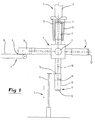
- Fig. 1 schematically illustrates a part of a packing machine of the type, for example, which is described in greater detail in European Patent EP 413.927, to which reference is now made.
- the portion of the packing machine illustrated in Fig. 1 comprises a mandrel wheel 1 which is stepwise rotary about a horizontal mandrel shaft 2.
- the mandrel wheel 1 comprises four mandrels 3 uniformly disposed about its periphery and which, by stepwise rotation of the mandrel wheel 1 in a clockwise direction, is displaceable between four different stations, viz. an infeed station 4, an injection moulding station 5, a cooling station 6 and a discharge station 7.
- the infeed station 4 further includes a conveyor 8 which is provided with carriers 9 so as to make possible the advancement and transfer of one casing 10 at a time to the mandrel 3 instantaneously stationary at the infeed station 4.
- each mandrel is provided with a portion accommodating the casing and a free mandrel end or mould portion 11 which forms a part of an end wall mould which is utilised to provide the casing 10 with an injection moulded end wall 12.
- the mould further includes additional mould sections, namely two external mould halves 13 which may be displaced between an open position in which the mandrel wheel 1 may be rotated such that a mandrel 3 may pass the mould halves 13 without hindrance, and a closed position (illustrated in Fig.
- the two external mould halves 13 tightly surround the mandrel 3 or, more correctly, the casing 10 placed on the mandrel 3 and leave only a limited space serving as mould cavity at the free end or core 11 of the mandrel.
- the external mould halves are directly or indirectly in communication with an extruder 14 or some other injection tool by means of which plastic mass heated to the desired temperature may be supplied at suitable pressure via a channel 13' to the mould cavity formed by the mould halves and the core.
- the cooling station 6 shown to the right in Fig. 1 is utilised only to afford the newly moulded end wall 12 the requisite cooling time, in which event the cooling cycle may possibly be accelerated with the aid of positive ventilation or the like.
- the discharge station 7 straight beneath the mandrel shaft 2, there is disposed the discharge station 7 in which a stripper 15, with the aid of a fork 16 surrounding the mandrel 3, is disposed to displace the packaging container blank 17 consisting of the casing 10 and the end wall 12 vertically downwards so that they are removed from the mandrel 3 and are transferred to transport means, for example a conveyor (not shown).
- the fork 16 is vertically reciprocal with the aid of, for example, a piston and cylinder unit.
- the mandrels 3 are provided with an air duct 18 which is intended to communicate the mandrel end with a source of gas or compressed air of conventional type (not shown) via an aperture in the end portion of the mandrels facing towards the mandrel shaft 2.
- the air duct 18 discharges in the mandrel end 11 or the core via an air-permeable device 19 which is placed in the mouth of the air duct 18.
- the free end of the air-permeable device is in the form of a substantially planar surface which is located flush with the surface of the mandrel end 11.
- the material of the air-permeable device may be spherical or irregularly-shaped particles of Nickel-coated bronze of a size (diameter) of 50-500 ⁇ .
- a packaging container of the type which is to be manufactured comprises, in addition to the casing 10 and end wall 12, also an opening arrangement 20 with a projecting pull ring 21 which are manufactured by injection moulding in one piece with the end wall 12.
- the pull ring 21 has relatively slight cross sectional area and the material (thermoplastic, e.g. polyethylene) will readily break since, immediately after the moulding operation, it has not had time to cool completely. Since the mould halves 13, when the mould is opened, first move in the longitudinal direction of the mandrel 3 (Figs.
- the mandrel wheel 1 (Fig. 1) is once again rotated so that the packaging container blank 17 reaches the cooling station 6, whereafter, by renewed rotation of the mandrel wheel 1, it is transferred to the discharge station 7 where the fork 16 of the stripper 15 grasps the edge of the packaging container blank 17 facing towards the mandrel shaft 2 and moves it downwards so that it is removed from the mandrel 3.
- the fork 16 of the stripper 15 grasps the edge of the packaging container blank 17 facing towards the mandrel shaft 2 and moves it downwards so that it is removed from the mandrel 3.
- a mechanical device which acts on the underside of the end wall 12 and, for example, is in the form of a plate or piston centrally disposed in the mandrel end, and whose underside is in communication with the air duct 18. The plate or piston will thus be lifted and force the central portion of the end wall out of engagement with the mandrel end when air begins to be supplied via the duct 18.
Landscapes
- Engineering & Computer Science (AREA)
- Manufacturing & Machinery (AREA)
- Mechanical Engineering (AREA)
- Moulds For Moulding Plastics Or The Like (AREA)
- Crystals, And After-Treatments Of Crystals (AREA)
- Processing Of Stones Or Stones Resemblance Materials (AREA)
- Mechanical Treatment Of Semiconductor (AREA)
- Blow-Moulding Or Thermoforming Of Plastics Or The Like (AREA)
- Processing And Handling Of Plastics And Other Materials For Molding In General (AREA)
Applications Claiming Priority (2)
| Application Number | Priority Date | Filing Date | Title |
|---|---|---|---|
| SE9700752 | 1997-03-03 | ||
| SE9700752A SE513948C2 (sv) | 1997-03-03 | 1997-03-03 | Sätt att lösgöra formade plastdetaljer vid formsprutning |
Publications (2)
| Publication Number | Publication Date |
|---|---|
| EP0862980A1 true EP0862980A1 (de) | 1998-09-09 |
| EP0862980B1 EP0862980B1 (de) | 2002-06-12 |
Family
ID=20405998
Family Applications (1)
| Application Number | Title | Priority Date | Filing Date |
|---|---|---|---|
| EP98100791A Expired - Lifetime EP0862980B1 (de) | 1997-03-03 | 1998-01-19 | Verfahren zum Strippen |
Country Status (6)
| Country | Link |
|---|---|
| EP (1) | EP0862980B1 (de) |
| JP (1) | JPH10244562A (de) |
| KR (1) | KR100356648B1 (de) |
| AT (1) | ATE218964T1 (de) |
| DE (1) | DE69805880T2 (de) |
| SE (1) | SE513948C2 (de) |
Cited By (9)
| Publication number | Priority date | Publication date | Assignee | Title |
|---|---|---|---|---|
| WO2002034494A1 (en) * | 2000-10-24 | 2002-05-02 | Vikan A/S | Method for moulding a tool handle |
| WO2004050326A1 (en) * | 2002-11-29 | 2004-06-17 | Tetra Laval Holdings & Finance S.A. | Injection moulding device and method |
| WO2004050327A1 (en) | 2002-11-29 | 2004-06-17 | Tetra Laval Holdings & Finance S.A. | Injection moulding device and a method of opening and closing a partible mould in an injection moulding device |
| RU2311326C2 (ru) * | 2002-01-21 | 2007-11-27 | Тетра Лаваль Холдингз Энд Файнэнс С.А. | Устройство для изготовления упаковок и способ его изготовления, а также способ изготовления и обработки упаковки и ее частей (варианты) и устройство для осуществления этого способа |
| US7313895B2 (en) * | 2004-07-20 | 2008-01-01 | Tetra Laval Holdings & Finance, Sa | Molding unit for forming direct injection molded closures |
| US8617039B2 (en) | 2002-12-13 | 2013-12-31 | Tetra Laval Holdings & Finance S.A. | Packaging device |
| EP2234785A4 (de) * | 2007-12-18 | 2015-04-15 | Tetra Laval Holdings & Finance | Vorrichtung und verfahren zum formen eines teils eines verpackungsbehälters |
| CN112092411A (zh) * | 2020-07-31 | 2020-12-18 | 北京卫星制造厂有限公司 | 一种小口径、长尺寸非等厚薄形矩形管件成型工装及方法 |
| WO2021089213A1 (en) * | 2019-11-05 | 2021-05-14 | Foboha (Germany) Gmbh | Device and method for manufacturing composite products with an injection-molded feature |
Families Citing this family (2)
| Publication number | Priority date | Publication date | Assignee | Title |
|---|---|---|---|---|
| US6352426B1 (en) | 1998-03-19 | 2002-03-05 | Advanced Plastics Technologies, Ltd. | Mold for injection molding multilayer preforms |
| MX2008002479A (es) | 2005-08-30 | 2008-04-07 | Advanced Plastics Technologies | Metodos y sistemas por controlar temperaturas de molde. |
Citations (6)
| Publication number | Priority date | Publication date | Assignee | Title |
|---|---|---|---|---|
| EP0079786A1 (de) * | 1981-11-16 | 1983-05-25 | J. Larry Underwood | Form, Verfahren zum Herstellen geformter Teile und nach diesem Verfahren hergestelltes Teil |
| US4653997A (en) * | 1985-08-16 | 1987-03-31 | Izon Industries Inc. Unit #11 | Injection mold apparatus with gas ejection |
| US4994228A (en) * | 1989-02-16 | 1991-02-19 | Fuji Photo Film Co., Ltd. | Method for releasing molded synthetic resin products from a mold |
| EP0413927A1 (de) * | 1989-08-17 | 1991-02-27 | Tetra Laval Holdings & Finance SA | Vorrichtung zur Herstellung einer Flüssigkeitspackung |
| WO1992022413A1 (en) * | 1991-06-12 | 1992-12-23 | Automotive Plastic Technologies, Inc. | Retractable gas injection pin for injection mold |
| JPH07148792A (ja) * | 1993-11-30 | 1995-06-13 | Sekisui Chem Co Ltd | 射出成形用金型 |
-
1997
- 1997-03-03 SE SE9700752A patent/SE513948C2/sv not_active IP Right Cessation
-
1998
- 1998-01-19 EP EP98100791A patent/EP0862980B1/de not_active Expired - Lifetime
- 1998-01-19 DE DE69805880T patent/DE69805880T2/de not_active Expired - Fee Related
- 1998-01-19 AT AT98100791T patent/ATE218964T1/de not_active IP Right Cessation
- 1998-02-27 KR KR10-1998-0006296A patent/KR100356648B1/ko not_active Expired - Fee Related
- 1998-03-02 JP JP10049242A patent/JPH10244562A/ja active Pending
Patent Citations (6)
| Publication number | Priority date | Publication date | Assignee | Title |
|---|---|---|---|---|
| EP0079786A1 (de) * | 1981-11-16 | 1983-05-25 | J. Larry Underwood | Form, Verfahren zum Herstellen geformter Teile und nach diesem Verfahren hergestelltes Teil |
| US4653997A (en) * | 1985-08-16 | 1987-03-31 | Izon Industries Inc. Unit #11 | Injection mold apparatus with gas ejection |
| US4994228A (en) * | 1989-02-16 | 1991-02-19 | Fuji Photo Film Co., Ltd. | Method for releasing molded synthetic resin products from a mold |
| EP0413927A1 (de) * | 1989-08-17 | 1991-02-27 | Tetra Laval Holdings & Finance SA | Vorrichtung zur Herstellung einer Flüssigkeitspackung |
| WO1992022413A1 (en) * | 1991-06-12 | 1992-12-23 | Automotive Plastic Technologies, Inc. | Retractable gas injection pin for injection mold |
| JPH07148792A (ja) * | 1993-11-30 | 1995-06-13 | Sekisui Chem Co Ltd | 射出成形用金型 |
Non-Patent Citations (1)
| Title |
|---|
| PATENT ABSTRACTS OF JAPAN vol. 1995, no. 09 31 October 1995 (1995-10-31) * |
Cited By (11)
| Publication number | Priority date | Publication date | Assignee | Title |
|---|---|---|---|---|
| WO2002034494A1 (en) * | 2000-10-24 | 2002-05-02 | Vikan A/S | Method for moulding a tool handle |
| RU2311326C2 (ru) * | 2002-01-21 | 2007-11-27 | Тетра Лаваль Холдингз Энд Файнэнс С.А. | Устройство для изготовления упаковок и способ его изготовления, а также способ изготовления и обработки упаковки и ее частей (варианты) и устройство для осуществления этого способа |
| US7390290B2 (en) | 2002-01-21 | 2008-06-24 | Tetra Laval Holdings & Finance S.A. | Packaging machine |
| WO2004050326A1 (en) * | 2002-11-29 | 2004-06-17 | Tetra Laval Holdings & Finance S.A. | Injection moulding device and method |
| WO2004050327A1 (en) | 2002-11-29 | 2004-06-17 | Tetra Laval Holdings & Finance S.A. | Injection moulding device and a method of opening and closing a partible mould in an injection moulding device |
| RU2322348C2 (ru) * | 2002-11-29 | 2008-04-20 | Тетра Лаваль Холдингз Энд Файнэнс С.А. | Устройство инжекционного формования и способ открытия и закрытия разделяемой пресс-формы в устройстве инжекционного формования |
| US8617039B2 (en) | 2002-12-13 | 2013-12-31 | Tetra Laval Holdings & Finance S.A. | Packaging device |
| US7313895B2 (en) * | 2004-07-20 | 2008-01-01 | Tetra Laval Holdings & Finance, Sa | Molding unit for forming direct injection molded closures |
| EP2234785A4 (de) * | 2007-12-18 | 2015-04-15 | Tetra Laval Holdings & Finance | Vorrichtung und verfahren zum formen eines teils eines verpackungsbehälters |
| WO2021089213A1 (en) * | 2019-11-05 | 2021-05-14 | Foboha (Germany) Gmbh | Device and method for manufacturing composite products with an injection-molded feature |
| CN112092411A (zh) * | 2020-07-31 | 2020-12-18 | 北京卫星制造厂有限公司 | 一种小口径、长尺寸非等厚薄形矩形管件成型工装及方法 |
Also Published As
| Publication number | Publication date |
|---|---|
| JPH10244562A (ja) | 1998-09-14 |
| DE69805880D1 (de) | 2002-07-18 |
| KR19980079772A (ko) | 1998-11-25 |
| SE513948C2 (sv) | 2000-12-04 |
| ATE218964T1 (de) | 2002-06-15 |
| SE9700752D0 (sv) | 1997-03-03 |
| EP0862980B1 (de) | 2002-06-12 |
| SE9700752L (sv) | 1998-09-04 |
| DE69805880T2 (de) | 2002-10-02 |
| KR100356648B1 (ko) | 2003-02-07 |
Similar Documents
| Publication | Publication Date | Title |
|---|---|---|
| AU2008346549B2 (en) | Method and device for producing containers made of thermoplastic and containers so produced | |
| US7140863B2 (en) | Method for producing a container from a thermoplastic film, and molding tool for executing the method | |
| EP0862980B1 (de) | Verfahren zum Strippen | |
| US6406288B2 (en) | Apparatus for extrusion molding utilizing clamping devices and means for releasing compressed air | |
| CA1242859A (en) | Method for blow-molding a container having a neck- portion with internal attachment means | |
| EP0539169B1 (de) | Artikel mit Form zur Erfassung der Position sowie Verfahren und Vorrichtung zur deren Herstellung und Verarbeitung | |
| JPH0539858Y2 (de) | ||
| US5454708A (en) | Flash removal system for a mold | |
| EP0486419B1 (de) | Verfahren zum Blasformen von thermoplastischen Kunstharzen | |
| CZ337496A3 (en) | Process and apparatus for producing profiles body of plastic | |
| US3375551A (en) | Apparatus for making an open-end container having a curled rim | |
| US3911075A (en) | Transfer molding thermosetting polymeric material | |
| MX2008016019A (es) | Aparato para objetos moldeados por compresion. | |
| US20220048238A1 (en) | Half shell | |
| JP2000301597A5 (de) | ||
| JPS59201823A (ja) | 熱可塑性プラスチックから吹込成形体を製造する方法及び装置 | |
| JPH05253966A (ja) | 多層薄肉容器の製造装置 | |
| CN213947396U (zh) | 一种吹塑嵌件模具及吹塑嵌件装置 | |
| US20060017189A1 (en) | Molding arrangement and method including vacuum assisted ventilation | |
| JPH04284224A (ja) | 圧空及び真空又は圧空真空成形装置並びにその成形方法 | |
| JP2964049B2 (ja) | 樹脂成形品のブロー成形方法および装置 | |
| AU2006202239B2 (en) | Moulding method | |
| JP2002513342A (ja) | 押出成形方法および関連装置 | |
| JP3801281B2 (ja) | ボトルパック容器の成形装置 | |
| SU1235749A1 (ru) | Литьева форма |
Legal Events
| Date | Code | Title | Description |
|---|---|---|---|
| PUAI | Public reference made under article 153(3) epc to a published international application that has entered the european phase |
Free format text: ORIGINAL CODE: 0009012 |
|
| AK | Designated contracting states |
Kind code of ref document: A1 Designated state(s): AT BE CH DE DK ES FI FR GB GR IE IT LI LU NL PT SE |
|
| AX | Request for extension of the european patent |
Free format text: AL;LT;LV;MK;RO;SI |
|
| 17P | Request for examination filed |
Effective date: 19990309 |
|
| AKX | Designation fees paid |
Free format text: AT BE CH DE DK ES FI FR GB GR IE IT LI LU NL PT SE |
|
| RBV | Designated contracting states (corrected) |
Designated state(s): AT BE CH DE DK ES FI FR GB GR IE IT LI LU NL PT SE |
|
| 17Q | First examination report despatched |
Effective date: 20000620 |
|
| GRAG | Despatch of communication of intention to grant |
Free format text: ORIGINAL CODE: EPIDOS AGRA |
|
| GRAG | Despatch of communication of intention to grant |
Free format text: ORIGINAL CODE: EPIDOS AGRA |
|
| GRAH | Despatch of communication of intention to grant a patent |
Free format text: ORIGINAL CODE: EPIDOS IGRA |
|
| GRAH | Despatch of communication of intention to grant a patent |
Free format text: ORIGINAL CODE: EPIDOS IGRA |
|
| GRAA | (expected) grant |
Free format text: ORIGINAL CODE: 0009210 |
|
| RIN1 | Information on inventor provided before grant (corrected) |
Inventor name: HARNFELDT, LARS-OLOF |
|
| AK | Designated contracting states |
Kind code of ref document: B1 Designated state(s): AT BE CH DE DK ES FI FR GB GR IE IT LI LU NL PT SE |
|
| PG25 | Lapsed in a contracting state [announced via postgrant information from national office to epo] |
Ref country code: NL Free format text: LAPSE BECAUSE OF FAILURE TO SUBMIT A TRANSLATION OF THE DESCRIPTION OR TO PAY THE FEE WITHIN THE PRESCRIBED TIME-LIMIT Effective date: 20020612 Ref country code: LI Free format text: LAPSE BECAUSE OF FAILURE TO SUBMIT A TRANSLATION OF THE DESCRIPTION OR TO PAY THE FEE WITHIN THE PRESCRIBED TIME-LIMIT Effective date: 20020612 Ref country code: GR Free format text: LAPSE BECAUSE OF FAILURE TO SUBMIT A TRANSLATION OF THE DESCRIPTION OR TO PAY THE FEE WITHIN THE PRESCRIBED TIME-LIMIT Effective date: 20020612 Ref country code: FI Free format text: LAPSE BECAUSE OF FAILURE TO SUBMIT A TRANSLATION OF THE DESCRIPTION OR TO PAY THE FEE WITHIN THE PRESCRIBED TIME-LIMIT Effective date: 20020612 Ref country code: CH Free format text: LAPSE BECAUSE OF FAILURE TO SUBMIT A TRANSLATION OF THE DESCRIPTION OR TO PAY THE FEE WITHIN THE PRESCRIBED TIME-LIMIT Effective date: 20020612 Ref country code: BE Free format text: LAPSE BECAUSE OF FAILURE TO SUBMIT A TRANSLATION OF THE DESCRIPTION OR TO PAY THE FEE WITHIN THE PRESCRIBED TIME-LIMIT Effective date: 20020612 Ref country code: AT Free format text: LAPSE BECAUSE OF FAILURE TO SUBMIT A TRANSLATION OF THE DESCRIPTION OR TO PAY THE FEE WITHIN THE PRESCRIBED TIME-LIMIT Effective date: 20020612 |
|
| REF | Corresponds to: |
Ref document number: 218964 Country of ref document: AT Date of ref document: 20020615 Kind code of ref document: T |
|
| REG | Reference to a national code |
Ref country code: GB Ref legal event code: FG4D |
|
| REG | Reference to a national code |
Ref country code: CH Ref legal event code: EP |
|
| REF | Corresponds to: |
Ref document number: 69805880 Country of ref document: DE Date of ref document: 20020718 |
|
| REG | Reference to a national code |
Ref country code: IE Ref legal event code: FG4D |
|
| PG25 | Lapsed in a contracting state [announced via postgrant information from national office to epo] |
Ref country code: DK Free format text: LAPSE BECAUSE OF FAILURE TO SUBMIT A TRANSLATION OF THE DESCRIPTION OR TO PAY THE FEE WITHIN THE PRESCRIBED TIME-LIMIT Effective date: 20020912 |
|
| PG25 | Lapsed in a contracting state [announced via postgrant information from national office to epo] |
Ref country code: PT Free format text: LAPSE BECAUSE OF FAILURE TO SUBMIT A TRANSLATION OF THE DESCRIPTION OR TO PAY THE FEE WITHIN THE PRESCRIBED TIME-LIMIT Effective date: 20020916 |
|
| ET | Fr: translation filed | ||
| NLV1 | Nl: lapsed or annulled due to failure to fulfill the requirements of art. 29p and 29m of the patents act | ||
| PG25 | Lapsed in a contracting state [announced via postgrant information from national office to epo] |
Ref country code: ES Free format text: LAPSE BECAUSE OF FAILURE TO SUBMIT A TRANSLATION OF THE DESCRIPTION OR TO PAY THE FEE WITHIN THE PRESCRIBED TIME-LIMIT Effective date: 20021220 |
|
| REG | Reference to a national code |
Ref country code: CH Ref legal event code: PL |
|
| PG25 | Lapsed in a contracting state [announced via postgrant information from national office to epo] |
Ref country code: LU Free format text: LAPSE BECAUSE OF NON-PAYMENT OF DUE FEES Effective date: 20030119 |
|
| PG25 | Lapsed in a contracting state [announced via postgrant information from national office to epo] |
Ref country code: IE Free format text: LAPSE BECAUSE OF NON-PAYMENT OF DUE FEES Effective date: 20030120 |
|
| PLBE | No opposition filed within time limit |
Free format text: ORIGINAL CODE: 0009261 |
|
| STAA | Information on the status of an ep patent application or granted ep patent |
Free format text: STATUS: NO OPPOSITION FILED WITHIN TIME LIMIT |
|
| 26N | No opposition filed |
Effective date: 20030313 |
|
| REG | Reference to a national code |
Ref country code: IE Ref legal event code: MM4A |
|
| PGFP | Annual fee paid to national office [announced via postgrant information from national office to epo] |
Ref country code: GB Payment date: 20070125 Year of fee payment: 10 |
|
| PGFP | Annual fee paid to national office [announced via postgrant information from national office to epo] |
Ref country code: SE Payment date: 20070129 Year of fee payment: 10 |
|
| PGFP | Annual fee paid to national office [announced via postgrant information from national office to epo] |
Ref country code: DE Payment date: 20070228 Year of fee payment: 10 |
|
| PGFP | Annual fee paid to national office [announced via postgrant information from national office to epo] |
Ref country code: IT Payment date: 20070519 Year of fee payment: 10 |
|
| PGFP | Annual fee paid to national office [announced via postgrant information from national office to epo] |
Ref country code: FR Payment date: 20070117 Year of fee payment: 10 |
|
| EUG | Se: european patent has lapsed | ||
| GBPC | Gb: european patent ceased through non-payment of renewal fee |
Effective date: 20080119 |
|
| PG25 | Lapsed in a contracting state [announced via postgrant information from national office to epo] |
Ref country code: DE Free format text: LAPSE BECAUSE OF NON-PAYMENT OF DUE FEES Effective date: 20080801 |
|
| REG | Reference to a national code |
Ref country code: FR Ref legal event code: ST Effective date: 20081029 |
|
| PG25 | Lapsed in a contracting state [announced via postgrant information from national office to epo] |
Ref country code: GB Free format text: LAPSE BECAUSE OF NON-PAYMENT OF DUE FEES Effective date: 20080119 |
|
| PG25 | Lapsed in a contracting state [announced via postgrant information from national office to epo] |
Ref country code: SE Free format text: LAPSE BECAUSE OF NON-PAYMENT OF DUE FEES Effective date: 20080120 |
|
| PG25 | Lapsed in a contracting state [announced via postgrant information from national office to epo] |
Ref country code: FR Free format text: LAPSE BECAUSE OF NON-PAYMENT OF DUE FEES Effective date: 20080131 |
|
| PG25 | Lapsed in a contracting state [announced via postgrant information from national office to epo] |
Ref country code: IT Free format text: LAPSE BECAUSE OF NON-PAYMENT OF DUE FEES Effective date: 20080119 |