EP0863107B1 - Korkenzieher - Google Patents
Korkenzieher Download PDFInfo
- Publication number
- EP0863107B1 EP0863107B1 EP97122227A EP97122227A EP0863107B1 EP 0863107 B1 EP0863107 B1 EP 0863107B1 EP 97122227 A EP97122227 A EP 97122227A EP 97122227 A EP97122227 A EP 97122227A EP 0863107 B1 EP0863107 B1 EP 0863107B1
- Authority
- EP
- European Patent Office
- Prior art keywords
- screw
- corkscrew according
- handle
- stem
- corkscrew
- Prior art date
- Legal status (The legal status is an assumption and is not a legal conclusion. Google has not performed a legal analysis and makes no representation as to the accuracy of the status listed.)
- Expired - Lifetime
Links
- 241001661918 Bartonia Species 0.000 claims abstract description 12
- 229910000831 Steel Inorganic materials 0.000 claims abstract description 4
- 230000002093 peripheral effect Effects 0.000 claims abstract description 4
- 239000010959 steel Substances 0.000 claims abstract description 4
- 238000007747 plating Methods 0.000 claims description 4
- 239000011248 coating agent Substances 0.000 claims description 3
- 238000000576 coating method Methods 0.000 claims description 3
- 230000006835 compression Effects 0.000 claims description 3
- 238000007906 compression Methods 0.000 claims description 3
- 238000004534 enameling Methods 0.000 claims description 3
- 230000000717 retained effect Effects 0.000 abstract description 2
- 239000007799 cork Substances 0.000 description 20
- POIUWJQBRNEFGX-XAMSXPGMSA-N cathelicidin Chemical compound C([C@@H](C(=O)N[C@@H](CCCNC(N)=N)C(=O)N[C@@H](CCCCN)C(=O)N[C@@H](CO)C(=O)N[C@@H](CCCCN)C(=O)N[C@@H](CCC(O)=O)C(=O)N[C@@H](CCCCN)C(=O)N[C@@H]([C@@H](C)CC)C(=O)NCC(=O)N[C@@H](CCCCN)C(=O)N[C@@H](CCC(O)=O)C(=O)N[C@@H](CC=1C=CC=CC=1)C(=O)N[C@@H](CCCCN)C(=O)N[C@@H](CCCNC(N)=N)C(=O)N[C@@H]([C@@H](C)CC)C(=O)N[C@@H](C(C)C)C(=O)N[C@@H](CCC(N)=O)C(=O)N[C@@H](CCCNC(N)=N)C(=O)N[C@@H]([C@@H](C)CC)C(=O)N[C@@H](CCCCN)C(=O)N[C@@H](CC(O)=O)C(=O)N[C@@H](CC=1C=CC=CC=1)C(=O)N[C@@H](CC(C)C)C(=O)N[C@@H](CCCNC(N)=N)C(=O)N[C@@H](CC(N)=O)C(=O)N[C@@H](CC(C)C)C(=O)N[C@@H](C(C)C)C(=O)N1[C@@H](CCC1)C(=O)N[C@@H](CCCNC(N)=N)C(=O)N[C@@H]([C@@H](C)O)C(=O)N[C@@H](CCC(O)=O)C(=O)N[C@@H](CO)C(O)=O)NC(=O)[C@H](CC=1C=CC=CC=1)NC(=O)[C@H](CC(O)=O)NC(=O)CNC(=O)[C@H](CC(C)C)NC(=O)[C@@H](N)CC(C)C)C1=CC=CC=C1 POIUWJQBRNEFGX-XAMSXPGMSA-N 0.000 description 4
- PXHVJJICTQNCMI-UHFFFAOYSA-N Nickel Chemical compound [Ni] PXHVJJICTQNCMI-UHFFFAOYSA-N 0.000 description 2
- 238000000605 extraction Methods 0.000 description 2
- 238000004519 manufacturing process Methods 0.000 description 2
- 239000007787 solid Substances 0.000 description 2
- VYZAMTAEIAYCRO-UHFFFAOYSA-N Chromium Chemical compound [Cr] VYZAMTAEIAYCRO-UHFFFAOYSA-N 0.000 description 1
- RYGMFSIKBFXOCR-UHFFFAOYSA-N Copper Chemical compound [Cu] RYGMFSIKBFXOCR-UHFFFAOYSA-N 0.000 description 1
- ATJFFYVFTNAWJD-UHFFFAOYSA-N Tin Chemical compound [Sn] ATJFFYVFTNAWJD-UHFFFAOYSA-N 0.000 description 1
- 239000000956 alloy Substances 0.000 description 1
- 229910045601 alloy Inorganic materials 0.000 description 1
- 229910052802 copper Inorganic materials 0.000 description 1
- 239000010949 copper Substances 0.000 description 1
- 239000002184 metal Substances 0.000 description 1
- 229910052751 metal Inorganic materials 0.000 description 1
- 238000000034 method Methods 0.000 description 1
- 229910052759 nickel Inorganic materials 0.000 description 1
- 239000004033 plastic Substances 0.000 description 1
- 229920003023 plastic Polymers 0.000 description 1
- 230000000630 rising effect Effects 0.000 description 1
- 210000002105 tongue Anatomy 0.000 description 1
Images



Classifications
-
- B—PERFORMING OPERATIONS; TRANSPORTING
- B67—OPENING, CLOSING OR CLEANING BOTTLES, JARS OR SIMILAR CONTAINERS; LIQUID HANDLING
- B67B—APPLYING CLOSURE MEMBERS TO BOTTLES JARS, OR SIMILAR CONTAINERS; OPENING CLOSED CONTAINERS
- B67B7/00—Hand- or power-operated devices for opening closed containers
- B67B7/02—Hand- or power-operated devices for opening closed containers for removing stoppers
- B67B7/04—Cork-screws
- B67B7/0417—Cork-screws with supporting means for assisting the pulling action
- B67B7/0447—Cork-screws with supporting means for assisting the pulling action whereby the supporting means abut around parts of the periphery of the neck of the bottle
Definitions
- the invention relates to a corkscrew according to the generic portion of claim 1.
- Corkscrews have been known for centuries.
- a particular type as disclosed in US 310,766 (B. Wilhelm) includes a handle mounted to a cone-shaped part the bottom of which has a circular groove for receiving two semi-circular tongues. These surround a screw and form the upper ends of loose prongs having inner shoulders that are capped by a slidable ring.
- a screw stem comprising a bearing disk is fixed to the handle so as to axially hold the components together.
- the screw tip is turned into a cork and the ring is slid up or down, respectively, so that the lower prong ends will first be spread and then moved together as lower prong shoulders are placed onto the neck of a bottle; further turning of the handle will force the cork up between the prongs while the device is pressed onto the bottle.
- corkscrews of similar type include a housing or bell that is solid with two prongs. These have inner semi-circular stops to be placed onto a bottle-neck. Under a firm grip to hold the bottle and housing together, a loose screw or worm can be put through a housing top portion that serves for guiding the screw which, upon turning, will enter the cork. As the latter raises between lateral ribs of the housing, it will thereby be held against rotation; once it is lifted out of the bottle, simple counter-turning of the screw handle will eject the cork from the bell.
- corkscrews named after Reissmann have a tapped stem screw borne within a matchingtapped bush of a bell or housing.
- a tiltable top nut through which a handle rod transversely extends also screws with the stem thread.
- the invention aims at overcoming these and other drawbacks of the prior art. It is an object of the invention to create a corkscrew that combines advantages of earlier designs in a simple and economical manner.
- a particular object of the invention is the creation of a two-prong corkscrew of sturdy design that permits fairly cheap manufacture and easy use, especially with well centered application onto bottle-necks of various sizes.
- the invention also aims at providing a cork-screw whose screw proper is surface-treated for minimum friction and is designed for easy piercing into a cork and for large engagement area therein.
- a corkscrew including a handle mounted to a screw stem rotatably guided within a cap which contains upper ends of two prongs having semi-circular lower ends that surround a screw and comprise inner shoulder stops adapted for engagement on a bottle-neck
- the improvement according to the invention is characterized in that the upper prong ends are articulated to a core unit to which a guide bush for the screw stem is associated and in that they are spring-biassed to provide a spreading force towards the perimeter of the cap.
- the cap may be integral with the handle, or the latter may be screw-fitted to a tapped stem which is guided by the cap.
- the core unit includes bearing means for the upper prong ends on which expanding springs bear and which have and/or find stops in the region of a lower peripheral edge of the cap.
- each of the upper prong ends comprises a lug for support on a pin that traverses guiding cheeks of the core unit on either outward side of the guide bush.
- Cork retaining and removing means in a bell include radial ribs having lower leading edges in each central portion of the prongs.
- Various types of screws or worms can be exchangeably used; preferred is a bladed type having wide sharp flares or a round wire hollow helix, either ending in a pointed tip.
- the screw is made of steel and is surface-treated for minimum friction, e.g. by plating, enameling or teflon-coating. It may conically widen downwards and thus be captive in respect of the core unit in which it is guided.
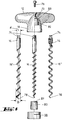
- FIGs. 1 to 6 A preferred embodiment of a corkscrew 10 according to the invention will be seen in Figs. 1 to 6. It includes a handle 12 to which a screw stem 14 having a worm or screw 16 is fixed exchangeably. A cap 18 is integral with the handle 12 and tops a core unit 20 as well as a guide bush 22 having a bore 23 (Figs. 5 and 6) in which the screw stem 14 and the screw 16 proper, respectively, are guided.
- Two prongs 40 preferably of metal have upper ends 42 which are articulated to a socket 26 of core unit 20 and are biassed by springs 56 so that the lower ends 48 of the prongs 40 would easily fit over bottle-necks (not shown) of various sizes.
- a flange 24 of core unit 20 separates the guide bush 22 from the upper ends 42 and may serve as a stop to these, just as a shoulder 28 of socket 26.
- the latter includes two pairs of parallel cheeks 30 defining radial chambers 36 and having transverse bores 32 in order to receive pins 34 which also pass through transverse bores 52 in lugs 50 of the upper prong ends 42.
- the lugs 50 contain blind holes 54 for seating outer ends 58 of compression springs 56 which bear on an outer portion 62 of each of the upper ends 42 for limited spreading of the prongs 40. Inner ends 57 of the springs 56 are each contained in the chamber 36 and bear on a wall 59 therein.
- a sliding ring 38 (Fig. 4) may snugly encompass the socket 26 as well as the outer portions 62 inside cap 18 for reducing friction during the cork extracting operation.
- a sleeve 80 may snugly fit the guide bush 22 inside a handle collet 82.
- the prongs 40 have a central portion 46 comprising opposite ribs 44 that extend radially from inner prong walls 47.
- Each rib 44 has a lower leading edge 45 that may be curved or slanted relative to the corkscrew axis A and serves for receiving a rising cork which is then retained between the ribs 44 until, after extraction, the cork is pushed off as handle 12 is counter-turned. The expelled cork will automatically fall out of the corkscrew 10 from between its slightly spreaded prongs 40.
- shoulder stops 64 preferably made of plastics are seated in an inner groove 66 and are anchored by a detent 68; they serve for rather gentle engagement on the bottle-neck.
- the lower ends 48 are curved outwardly to facilitate gripping a bottle-neck.
- a preferred worm or screw 16 includes a stem 14 having an upper square 74 which fits into a square hole 72 of handle 12 and which can be fixed thereto by means of a bolt 76 (Fig. 4).
- the pitched screw 16 is of the bladed type and comprises wide coil flares that are bevelled or cyphered to provide a continuous sharp helical edge ending in a pointed tip 78.
- the flare area or effective cross section is large and thus warrants ample engagement in a cork so that even if in a deteriorated state, the cork is very likely to be lifted out of the bottle.
- a steep-pitched center worm or screw 16' may be employed (lefthand in Fig. 4).
- Yet another worm or screw 16'' of the hollow helical type (righthand in Fig. 4) may also be inserted in handle 12 and likewise be fixed via a square connection 74/72.
- the worm or screw 16 proper may include a bolt portion 90 that screws with a threaded hole 92 in the stem 14 or stem extension 84.
- Handle 12 and screw 16 may be captive in respect of core unit 20.
- the example of Fig. 4/lefthand shows that the lower end of screw 16' may slightly widen towards its tip 78, e.g. conically, so that the lower screw end has adjacent tip 78 a somewhat larger outer diameter D than any other screw portion.
- a bore 81 of inner diameter d in sleeve 80 which is put over the top of the screw 16', matches the latter's outer diameter in particular at its top and central portions and is likewise slightly smaller than the outer diameter D of the lower screw end.
- Sleeve 80 serves, in addition, as a bearing inside handle collet 22 (Fig. 4). If, after extraction of a cork, the screw 16' is counter-turned for unscrewing from the cork, whereby the screw 16' usually rises relative to socket 20, the wider lower screw end will clampingly engage the smaller bore 81 so that sleeve 80 will also counter-turn in a bearing bush 83 inside the collet 22 in whose central bore 23 the screw body is guided. This clamping connection between the sleeve 80 and the lower screw end will be released immediately as handle 12 and thus screw 16' is turned again in screwing direction.
- the worm or screw 16 (or 16' or 16'') is preferably made of steel and is surface-treated for minimum friction, in particular by a plating process on the basis of copper, nickel, chrome, tin or alloys thereof. Velvet finish nickel-plating, enameling and teflon-coating may also be used.
- a second corkscrew embodiment is shown in Figs. 7 to 10. It is of the Reissmann type and includes a handle 12 adapted to be inserted in a tiltable nut 86 and provided with a tapped bore 88. Nut 86 and bore 88 match the thread of a tapped extension 84 of stem 14 and screw 16, respectively.
- the latter here comprises a bolt portion 90 designed to be screwed into a threaded hole 92 of tapped stem extension 84 with a stop ring 85 interposed.
- guide bush 22 is integral with cap 18 rather than with core unit 20.
- Cap 18 also includes a lower stop edge 60.
- Guide bush 22 here guides the tapped stem extension 84 the top of which forms a captive screw so that nut 86 previously mounted cannot spin off.
- a snap ring 70 may be seated, especially in a peripheral flute (merely indicated in Fig. 7), at the lower ends 48 of prongs 40 of either corkscrew embodiment. Snap ring 70 equals or exceeds the spreading force of springs 56 and serves to hold the prongs 40 resiliently together, especially to assist centered application on a bottle-neck, but also to facilitate the grip thereon and/or to retain the device when the corkscrew 10 is stationed on a table or on an extra wooden post (not shown) prior to use.
Landscapes
- Engineering & Computer Science (AREA)
- Mechanical Engineering (AREA)
- Devices For Opening Bottles Or Cans (AREA)
- Eye Examination Apparatus (AREA)
Claims (19)
- Korkenzieher (10) mit einem Griff (12), der an einem Schraubschaft (14) befestigt ist, welcher in einer Kappe (18) drehbar gelagert ist, die obere Enden (42) zweier Schenkel (40) übergreift, deren halbkreisförmige untere Enden (48) eine Schraubspindel (16) umschließen und innen Anschlagteile (64) zur Anlage an einem Flaschenhals aufweisen, dadurch gekennzeichnet, daß die oberen Schenke-Enden (42) an ein Mittelstück (20) angelenkt sind, dem eine Führungsbuchse (22) für die Schraubspindel (16) zugeordnet ist, und daß sie mit Spreizkraft zum Umfang der Kappe (18) hin federbelastet sind.
- Korkenzieher nach Anspruch 1, dadurch gekennzeichnet, daß die Kappe (18) einstückig mit dem Griff (12) ist.
- Korkenzieher nach Anspruch 1, dadurch gekennzeichnet, daß die Kappe (18) oder ein darin gehalterter Gleitring (38) eine untere Kante (60) als Anschlag für eine Außenfläche (62) jedes oberen Schenkel-Endes (42) aufweist.
- Korkenzieher nach Anspruch 1, dadurch gekennzeichnet, daß das Mittelstück (20) neben der Führungsbuchse (22) quer zur Mittelstück-Achse (A) zwei parallele Lagerungen (30, 32, 43) für die Gelenke der Schenkel (40) hat.
- Korkenzieher nach Anspruch 1, dadurch gekennzeichnet, daß das Mittelstück (20) beiderseits der Führungsbuchse (22) jeweils eine Anlagefläche (62) für ein inneres Ende (57) einer Druckfeder (56) hat, deren gegenüberliegendes äußeres Ende (58) in einem Sackloch (54) eines zugeordneten oberen Schenke-Endes (42) sitzt.
- Korkenzieher nach Anspruch 1, dadurch gekennzeichnet, daß die oberen Enden (42) jeweils einen Ansatz (50) mit einem Querloch (52) aufweisen, das mit einer Querbohrung (32) in parallelen Wangen (30) des Mittelstücks (20) übereinstimmt, und daß zur Halterung des Ansatzes (50) jeweils Stifte (34) die übereinstimmenden Bohrungen (32, 52) durchsetzen.
- Korkenzieher nach Anspruch 5 und 6, dadurch gekennzeichnet, daß die parallelen Wangen (30) eine Kammer (36) zur gleitbaren Aufnahme eines blockförmigen Ansatzes (50) begrenzen und daß jedes Sackloch (54) radial in dem Ansatz (50) unterhalb des zugeordneten Querlochs (52) angeordnet ist.
- Korkenzieher nach Anspruch 1, dadurch gekennzeichnet, daß jeder Schenkel (40) eine radiale Rippe (44) aufweist, die vom oberen Ende (42) abwärts verläuft und unten eine zu einer Schenkelwand (47) hin gekrümmte oder verjüngte Einlaufkante (45) hat.
- Korkenzieher nach Anspruch 1, dadurch gekennzeichnet, daß jeder Schenkel (40) eine Innennut (66) mit einer Raste (68) für einen halbrunden Anschlagteil (64) hat.
- Korkenzieher nach Anspruch 1, dadurch gekennzeichnet, daß der Schraubschaft (14) an dem Griff (12) austauschbar befestigt ist.
- Korkenzieher nach Anspruch 1, dadurch gekennzeichnet, daß der Schraubschaft (14) oben einen Vierkant (74) aufweist, der in ein Vierkantloch (72) des Griffes (12) einführbar und mit diesem verschraubbar ist.
- Korkenzieher nach Anspruch 1, dadurch gekennzeichnet, daß der Griff (12) eine Gewindebohrung (88) für die Schraubbefestigung einer Gewindestange (84) hat, deren Oberteil eine unverlierbare Schraube bildet, und daß die Kappe (18) einstückig mit der Führungsbuchse (22) ist, durch welche die Gewindestange (84) ragt.
- Korkenzieher nach Anspruch 12, dadurch gekennzeichnet, daß die Schraubspindel (16) einen oberen Gewindeansatz (90) zur lösbaren Befestigung an der Gewindestange (84) mit zwischengelagertem Anschlagring (85) aufweist.
- Korkenzieher nach Anspruch 1, dadurch gekennzeichnet, daß an den unteren Enden (48) der Schenkel (42) ein Schnurring (90) anbringbar ist, dessen Ziehkraft der Spreizkraft der Schenkelfedern (56) gleichkommt oder sie überschreitet.
- Korkenzieher nach Anspruch 1, dadurch gekennzeichnet, daß zur Gleitpassung des Sockels (26) ein Gleitring (38) und/oder zur Gleitpassung der Führungsbuchse (22) eine Hülse (80) vorhanden ist.
- Korkenzieher nach Anspruch 1, dadurch gekennzeichnet, daß die Spindel (16') als unverlierbare Schraube ausgebildet ist, indem ihr Durchmesser (D) am unteren Ende nahe der Spitze (78) größer als an allen anderen Spindelteilen ist, und daß der Innendurchmesser (d) einer oberen Bohrung (81) einer die Spindel (16') von oben übergreifenden Hülse (80) kleiner als der Außendurchmesser (D) des unteren Spindelendes ist und an diesem zur Anlage bringbar ist, wodurch der mit dem Spindel-Oberteil verschraubte Griff (12) unverlierbar am Mittelstück (20) gehalten ist.
- Korkenzieher nach Anspruch 1, dadurch gekennzeichnet, daß die Spindel (16,16') als Schneidschraube ausgebildet und mit Gewindeflanken versehen ist, die so angefast oder gewölbt sind, daß sie eine kontinuierliche scharfkantige Wendel bilden, die in eine Spitze (78) ausläuft.
- Korkenzieher nach Anspruch 1, dadurch gekennzeichnet, daß die Spindel (16'') hohl und als Runddraht-Wendel ausgebildet ist, die in eine Spitze (78) ausläuft.
- Korkenzieher nach Anspruch 1, dadurch gekennzeichnet, daß die Spindel (16, 16', 16'') aus Stahl besteht und durch Oberflächenvergütung reibungsarm ist, z.B. durch Galvanisieren, Glasur oder Teflon- Beschichtung.
Applications Claiming Priority (2)
| Application Number | Priority Date | Filing Date | Title |
|---|---|---|---|
| US3788997P | 1997-02-10 | 1997-02-10 | |
| US37889P | 1997-02-10 |
Publications (2)
| Publication Number | Publication Date |
|---|---|
| EP0863107A1 EP0863107A1 (de) | 1998-09-09 |
| EP0863107B1 true EP0863107B1 (de) | 1999-06-16 |
Family
ID=21896903
Family Applications (1)
| Application Number | Title | Priority Date | Filing Date |
|---|---|---|---|
| EP97122227A Expired - Lifetime EP0863107B1 (de) | 1997-02-10 | 1997-12-17 | Korkenzieher |
Country Status (4)
| Country | Link |
|---|---|
| US (1) | US6401569B2 (de) |
| EP (1) | EP0863107B1 (de) |
| AT (1) | ATE181308T1 (de) |
| DE (1) | DE69700281T2 (de) |
Families Citing this family (20)
| Publication number | Priority date | Publication date | Assignee | Title |
|---|---|---|---|---|
| FR2774671B1 (fr) * | 1998-02-12 | 2000-03-17 | Birambeau | Perfectionnement aux meches de tire-bouchon |
| GB2365417B (en) | 2000-08-02 | 2002-06-26 | Kwok Kuen So | Corkscrew |
| EP1205431B1 (de) * | 2000-11-09 | 2006-08-16 | Wmf Württembergische Metallwarenfabrik Ag | Korkenzieher |
| US6732611B2 (en) | 2002-01-31 | 2004-05-11 | Francisco Jose Traspuesto Miguel | Articulated corkscrew |
| NL1019986C2 (nl) * | 2002-02-18 | 2003-08-19 | Vacu Vin Innovations Ltd | Kurkentrekker/flesvasthoudinrichting. |
| ATE342866T1 (de) * | 2002-04-15 | 2006-11-15 | Barthel Klaus | Korkenzieher |
| CN1298611C (zh) * | 2004-04-27 | 2007-02-07 | 陈苇 | 开瓶器 |
| US20060225536A1 (en) * | 2005-04-06 | 2006-10-12 | Thomas Hill | Bottle opener for pressurized bottles |
| US7832307B2 (en) * | 2005-05-24 | 2010-11-16 | Marisa MARCHIGNOLI | Corkscrew |
| USD572988S1 (en) * | 2007-01-25 | 2008-07-15 | Dart Industries Inc. | Corkscrew |
| US8365459B2 (en) * | 2007-02-15 | 2013-02-05 | Gary Bennis | Stem guide and replaceable cartridges |
| USD565914S1 (en) * | 2007-06-01 | 2008-04-08 | Li-Yu Teng | Electric screw driver |
| US20110100164A1 (en) * | 2009-10-30 | 2011-05-05 | Wki Holding Company, Inc. | Self-Pulling Corkscrew |
| US8915167B2 (en) | 2011-02-10 | 2014-12-23 | Aleksandar Ratajac | Cork screw |
| ITPG20120003A1 (it) * | 2012-01-31 | 2013-08-01 | Icork Di Melis Marco | Cavatappi con vermicello rimovibile. |
| USD928950S1 (en) * | 2019-10-01 | 2021-08-24 | Shukla Medical | T handle with male hub |
| USD921894S1 (en) * | 2019-11-14 | 2021-06-08 | ECA Medical Instruments, Inc. | Offset t-shaped handle for surgical tools |
| USD921893S1 (en) * | 2019-11-14 | 2021-06-08 | ECA Medical Instruments, Inc. | T-shaped handle for surgical tools |
| CN113942968B (zh) * | 2021-05-06 | 2023-06-23 | 中山市群升铝业有限公司 | 一种用于木塞酒瓶的旋转启瓶器 |
| CN219689305U (zh) * | 2023-05-08 | 2023-09-15 | 深圳璟都科技有限公司 | 一种安全的开瓶器 |
Family Cites Families (7)
| Publication number | Priority date | Publication date | Assignee | Title |
|---|---|---|---|---|
| US310766A (en) * | 1885-01-13 | Halp to john heney kamps | ||
| US518018A (en) * | 1894-04-10 | Eduard becker | ||
| US4377096A (en) * | 1979-03-05 | 1983-03-22 | Hallen Company | Cork extractor |
| US4800784A (en) * | 1988-03-15 | 1989-01-31 | Hallen Company | Apparatus for removing corks from bottles |
| US4703673A (en) * | 1985-04-08 | 1987-11-03 | Hallen Company | Cork-extracting apparatus |
| DE8809652U1 (de) * | 1988-07-26 | 1988-09-15 | Müller, Matthias, 1000 Berlin | Handwerkzeug zum Ent- und Wiederverkorken von Flaschen |
| ES1029130Y (es) * | 1994-12-13 | 1996-01-16 | Arguinao Enrique Aizpitarte | Nuevo sacacorchos portatil |
-
1997
- 1997-12-17 AT AT97122227T patent/ATE181308T1/de not_active IP Right Cessation
- 1997-12-17 EP EP97122227A patent/EP0863107B1/de not_active Expired - Lifetime
- 1997-12-17 DE DE69700281T patent/DE69700281T2/de not_active Expired - Fee Related
-
1998
- 1998-02-09 US US09/021,022 patent/US6401569B2/en not_active Expired - Fee Related
Also Published As
| Publication number | Publication date |
|---|---|
| ATE181308T1 (de) | 1999-07-15 |
| US20010039855A1 (en) | 2001-11-15 |
| DE69700281D1 (de) | 1999-07-22 |
| US6401569B2 (en) | 2002-06-11 |
| EP0863107A1 (de) | 1998-09-09 |
| DE69700281T2 (de) | 2000-02-03 |
Similar Documents
| Publication | Publication Date | Title |
|---|---|---|
| EP0863107B1 (de) | Korkenzieher | |
| KR860002067B1 (ko) | 코르크 마개발취장치 | |
| US6799490B1 (en) | Lever corkscrew | |
| US4253351A (en) | Cork extractor | |
| US4552276A (en) | Drinking vessel having a holder | |
| JPH0156992B2 (de) | ||
| US1753026A (en) | Cork extractor | |
| CA1135068A (en) | Cork extractor | |
| EP0231370A1 (de) | Öffner für sektflasche | |
| US6779213B2 (en) | Cork remover | |
| US5275070A (en) | Device for removing wine bottle stopper | |
| AU3888093A (en) | Tool for breaking a vacuum in a preserving jar closed with a screw cap | |
| US5829902A (en) | Adjustable applicator brush | |
| CA2036773C (en) | Collet-type cork remover with thumb receiving recess | |
| EP0294207A1 (de) | Verfahren und Gerät zum Entkorken einer Sektflasche, versehen mit einem Korken oder einem Kunststoffpfropfen | |
| AU8174687A (en) | Screw cap opener | |
| US20030177869A1 (en) | Corkscrew | |
| CN107572467B (zh) | 一种适应各种口径的起瓶器 | |
| EP0620184A1 (de) | Mehrzweckstopfen-Ziehvorrichtung für Weinflaschen | |
| EP4144686A1 (de) | Vorrichtung mit hebelelementen zum herausziehen eines flaschenverschlusses | |
| GB2401860A (en) | Lever corkscrew | |
| WO2000007926A3 (en) | Device for gripping containers and corkscrew provided with such device | |
| CN2318209Y (zh) | 启塞器 | |
| US20060225536A1 (en) | Bottle opener for pressurized bottles | |
| JP3039910U (ja) | 組み立て栓抜き |
Legal Events
| Date | Code | Title | Description |
|---|---|---|---|
| PUAI | Public reference made under article 153(3) epc to a published international application that has entered the european phase |
Free format text: ORIGINAL CODE: 0009012 |
|
| 17P | Request for examination filed |
Effective date: 19980609 |
|
| AK | Designated contracting states |
Kind code of ref document: A1 Designated state(s): AT BE CH DE FR GB IT LI NL |
|
| AX | Request for extension of the european patent |
Free format text: AL;LT;LV;MK;RO;SI |
|
| RAP1 | Party data changed (applicant data changed or rights of an application transferred) |
Owner name: MONOPOLWERK USBECK & SOEHNE GMBH & CO. |
|
| GRAG | Despatch of communication of intention to grant |
Free format text: ORIGINAL CODE: EPIDOS AGRA |
|
| GRAG | Despatch of communication of intention to grant |
Free format text: ORIGINAL CODE: EPIDOS AGRA |
|
| GRAH | Despatch of communication of intention to grant a patent |
Free format text: ORIGINAL CODE: EPIDOS IGRA |
|
| 17Q | First examination report despatched |
Effective date: 19981105 |
|
| GRAH | Despatch of communication of intention to grant a patent |
Free format text: ORIGINAL CODE: EPIDOS IGRA |
|
| GRAA | (expected) grant |
Free format text: ORIGINAL CODE: 0009210 |
|
| AKX | Designation fees paid | ||
| RBV | Designated contracting states (corrected) | ||
| RBV | Designated contracting states (corrected) |
Designated state(s): AT BE CH DE FR GB IT LI NL |
|
| AK | Designated contracting states |
Kind code of ref document: B1 Designated state(s): AT BE CH DE FR GB IT LI NL |
|
| REF | Corresponds to: |
Ref document number: 181308 Country of ref document: AT Date of ref document: 19990715 Kind code of ref document: T |
|
| REG | Reference to a national code |
Ref country code: CH Ref legal event code: EP |
|
| REF | Corresponds to: |
Ref document number: 69700281 Country of ref document: DE Date of ref document: 19990722 |
|
| ET | Fr: translation filed | ||
| ITF | It: translation for a ep patent filed | ||
| REG | Reference to a national code |
Ref country code: CH Ref legal event code: NV Representative=s name: PA ALDO ROEMPLER |
|
| PLBE | No opposition filed within time limit |
Free format text: ORIGINAL CODE: 0009261 |
|
| STAA | Information on the status of an ep patent application or granted ep patent |
Free format text: STATUS: NO OPPOSITION FILED WITHIN TIME LIMIT |
|
| 26N | No opposition filed | ||
| PGFP | Annual fee paid to national office [announced via postgrant information from national office to epo] |
Ref country code: BE Payment date: 20001211 Year of fee payment: 4 |
|
| PGFP | Annual fee paid to national office [announced via postgrant information from national office to epo] |
Ref country code: AT Payment date: 20001229 Year of fee payment: 4 |
|
| PG25 | Lapsed in a contracting state [announced via postgrant information from national office to epo] |
Ref country code: GB Free format text: LAPSE BECAUSE OF NON-PAYMENT OF DUE FEES Effective date: 20011217 Ref country code: AT Free format text: LAPSE BECAUSE OF NON-PAYMENT OF DUE FEES Effective date: 20011217 |
|
| PG25 | Lapsed in a contracting state [announced via postgrant information from national office to epo] |
Ref country code: LI Free format text: LAPSE BECAUSE OF NON-PAYMENT OF DUE FEES Effective date: 20011231 Ref country code: CH Free format text: LAPSE BECAUSE OF NON-PAYMENT OF DUE FEES Effective date: 20011231 Ref country code: BE Free format text: LAPSE BECAUSE OF NON-PAYMENT OF DUE FEES Effective date: 20011231 |
|
| REG | Reference to a national code |
Ref country code: GB Ref legal event code: IF02 |
|
| BERE | Be: lapsed |
Owner name: MONOPOLWERK USBECK & SOHNE G.M.B.H. & CO. Effective date: 20011231 |
|
| PG25 | Lapsed in a contracting state [announced via postgrant information from national office to epo] |
Ref country code: NL Free format text: LAPSE BECAUSE OF NON-PAYMENT OF DUE FEES Effective date: 20020701 |
|
| GBPC | Gb: european patent ceased through non-payment of renewal fee |
Effective date: 20011217 |
|
| REG | Reference to a national code |
Ref country code: CH Ref legal event code: PL |
|
| NLV4 | Nl: lapsed or anulled due to non-payment of the annual fee |
Effective date: 20020701 |
|
| PGFP | Annual fee paid to national office [announced via postgrant information from national office to epo] |
Ref country code: DE Payment date: 20031205 Year of fee payment: 7 |
|
| PGFP | Annual fee paid to national office [announced via postgrant information from national office to epo] |
Ref country code: FR Payment date: 20031209 Year of fee payment: 7 |
|
| PG25 | Lapsed in a contracting state [announced via postgrant information from national office to epo] |
Ref country code: DE Free format text: LAPSE BECAUSE OF NON-PAYMENT OF DUE FEES Effective date: 20050701 |
|
| PG25 | Lapsed in a contracting state [announced via postgrant information from national office to epo] |
Ref country code: FR Free format text: LAPSE BECAUSE OF NON-PAYMENT OF DUE FEES Effective date: 20050831 |
|
| REG | Reference to a national code |
Ref country code: FR Ref legal event code: ST |
|
| PG25 | Lapsed in a contracting state [announced via postgrant information from national office to epo] |
Ref country code: IT Free format text: LAPSE BECAUSE OF NON-PAYMENT OF DUE FEES;WARNING: LAPSES OF ITALIAN PATENTS WITH EFFECTIVE DATE BEFORE 2007 MAY HAVE OCCURRED AT ANY TIME BEFORE 2007. THE CORRECT EFFECTIVE DATE MAY BE DIFFERENT FROM THE ONE RECORDED. Effective date: 20051217 |