EP0863221A1 - Alliage fer-chrom de coulée avec grande précision et sa utilisation pour aubes de turnies - Google Patents
Alliage fer-chrom de coulée avec grande précision et sa utilisation pour aubes de turnies Download PDFInfo
- Publication number
- EP0863221A1 EP0863221A1 EP98103275A EP98103275A EP0863221A1 EP 0863221 A1 EP0863221 A1 EP 0863221A1 EP 98103275 A EP98103275 A EP 98103275A EP 98103275 A EP98103275 A EP 98103275A EP 0863221 A1 EP0863221 A1 EP 0863221A1
- Authority
- EP
- European Patent Office
- Prior art keywords
- precision casting
- turbine blade
- materials
- shroud
- present
- Prior art date
- Legal status (The legal status is an assumption and is not a legal conclusion. Google has not performed a legal analysis and makes no representation as to the accuracy of the status listed.)
- Granted
Links
Images



Classifications
-
- F—MECHANICAL ENGINEERING; LIGHTING; HEATING; WEAPONS; BLASTING
- F01—MACHINES OR ENGINES IN GENERAL; ENGINE PLANTS IN GENERAL; STEAM ENGINES
- F01D—NON-POSITIVE DISPLACEMENT MACHINES OR ENGINES, e.g. STEAM TURBINES
- F01D5/00—Blades; Blade-carrying members; Heating, heat-insulating, cooling or antivibration means on the blades or the members
- F01D5/12—Blades
- F01D5/28—Selecting particular materials; Particular measures relating thereto; Measures against erosion or corrosion
-
- C—CHEMISTRY; METALLURGY
- C22—METALLURGY; FERROUS OR NON-FERROUS ALLOYS; TREATMENT OF ALLOYS OR NON-FERROUS METALS
- C22C—ALLOYS
- C22C38/00—Ferrous alloys, e.g. steel alloys
- C22C38/18—Ferrous alloys, e.g. steel alloys containing chromium
- C22C38/40—Ferrous alloys, e.g. steel alloys containing chromium with nickel
- C22C38/52—Ferrous alloys, e.g. steel alloys containing chromium with nickel with cobalt
-
- F—MECHANICAL ENGINEERING; LIGHTING; HEATING; WEAPONS; BLASTING
- F01—MACHINES OR ENGINES IN GENERAL; ENGINE PLANTS IN GENERAL; STEAM ENGINES
- F01D—NON-POSITIVE DISPLACEMENT MACHINES OR ENGINES, e.g. STEAM TURBINES
- F01D5/00—Blades; Blade-carrying members; Heating, heat-insulating, cooling or antivibration means on the blades or the members
- F01D5/12—Blades
- F01D5/14—Form or construction
- F01D5/18—Hollow blades, i.e. blades with cooling or heating channels or cavities; Heating, heat-insulating or cooling means on blades
-
- F—MECHANICAL ENGINEERING; LIGHTING; HEATING; WEAPONS; BLASTING
- F05—INDEXING SCHEMES RELATING TO ENGINES OR PUMPS IN VARIOUS SUBCLASSES OF CLASSES F01-F04
- F05D—INDEXING SCHEME FOR ASPECTS RELATING TO NON-POSITIVE-DISPLACEMENT MACHINES OR ENGINES, GAS-TURBINES OR JET-PROPULSION PLANTS
- F05D2300/00—Materials; Properties thereof
- F05D2300/10—Metals, alloys or intermetallic compounds
- F05D2300/11—Iron
-
- F—MECHANICAL ENGINEERING; LIGHTING; HEATING; WEAPONS; BLASTING
- F05—INDEXING SCHEMES RELATING TO ENGINES OR PUMPS IN VARIOUS SUBCLASSES OF CLASSES F01-F04
- F05D—INDEXING SCHEME FOR ASPECTS RELATING TO NON-POSITIVE-DISPLACEMENT MACHINES OR ENGINES, GAS-TURBINES OR JET-PROPULSION PLANTS
- F05D2300/00—Materials; Properties thereof
- F05D2300/10—Metals, alloys or intermetallic compounds
- F05D2300/13—Refractory metals, i.e. Ti, V, Cr, Zr, Nb, Mo, Hf, Ta, W
- F05D2300/132—Chromium
Definitions
- This invention relates to high-Cr precision casting materials having excellent high-temperature properties and suitable for use as the materials of turbine blades and other components used in thermal electric power generation, as well as turbine blades made by using these casting materials as structural materials.
- Turbine blade materials used for high-temperature applications in steam turbine plants for thermal electric power generation include forged steel materials based on 12Cr steel, and superalloys.
- turbine blades for use in actual plants are being made by forging a stock while hot and then shaping it by cutting. In this manufacturing process, however, much material is shaved off and wasted because the stock is shaped by cutting.
- turbine blades have a complicated shape, a large number of cutting steps are required and, furthermore, electric discharge machining or other machining technique having low working efficiency must be employed for the shaping of an intricate cavity. Thus, an enormous cost and a considerable time have been required.
- an object of the present invention is to provide high-Cr precision casting materials which are capable of precision casting and, moreover, have excellent high-temperature strength, as well as inexpensive and highly reliable turbine blades made by using these casting materials and such turbine blades also having lighter weight.
- the present invention provides the following high-Cr precision casting materials (1) and (2) and turbine blades (3) to (5):
- the aforesaid high-Cr precision casting materials (1) and (2) are based on the results of intensive investigations conducted by the present inventors in order to improve high-temperature strength by using a high-Cr steel as a basic material and adding carefully selected alloying elements thereto.
- these precision casting materials have excellent high-temperature properties and are suitable for use as the structural materials of steam turbine blades.
- C carbon: C, together with N, forms carbonitrides and thereby contributes to the improvement of creep rupture strength. Moreover, C acts as an austenite-forming element to inhibit the formation of ⁇ -ferrite. If its content is less than 0.08%, no sufficient effect will be produced, while if its content is greater than 0.14%, the carbonitrides will aggregate during use to form coarse grains, resulting in a reduction in long-time high-temperature strength. In addition, high C contents will bring about poor weldability and may hence cause difficulties such as weld crack during the manufacture of precision-cast blades. For these reasons, C must not be added in an amount greater than that required to improve high-temperature strength by the formation of carbonitrides and to inhibit the formation of ⁇ -ferrite. Accordingly, the content of C should be in the range of 0.08 to 0.14% and preferably 0.09 to 0.12%.
- Si is effective as a deoxidizer. Moreover, Si is an element required to secure good melt flowability because, for cast steel materials, the melt needs to be flow into all the corners of the mold. However, since Si has the effect of causing a reduction in toughness and high-temperature strength and, moreover, promoting the formation of ⁇ -ferrite, it is necessary to keep its content as low as possible. If its content is less than 0.1%, sufficient melt flowability cannot be secured, while if its content is greater than 0.3%, difficulties as described above will manifest themselves. Accordingly, the content of Si should be in the range of 0.1 to 0.3% and preferably 0.15 to 0.25%.
- Mn manganese
- Mn is an element which is useful as a deoxidizer. Moreover, Mn has the effect of inhibiting the formation of ⁇ -ferrite. The formation of ⁇ -ferrite will cause a reduction in ductility and toughness and, moreover, a significant reduction in creep rupture strength which is one type of high-temperature strength. Consequently, it is necessary to add Mn with consideration for the balance between Si and other elements. On the other hand, an increase in Mn will cause a corresponding reduction in creep rupture strength. On the basis of these background data, Mn must be added in a controlled amount so that the creep rupture strength will not be detracted from and, moreover, no ⁇ -ferrite will be formed during the manufacture of large-sized cast steel articles.
- the addition of more than 1% of Si will cause a significant reduction in high-temperature strength, and the amount of Mn which is inevitably incorporated in steel materials is considered to be about 0.01%. Accordingly, the content of Mn should be in the range of 0.01 to 1% and preferably 0.03 to 0.6%.
- Cr chromium: Cr form a carbide and thereby contributes to the improvement of creep rupture strength. Moreover, Cr dissolves in the matrix to improve oxidation resistance and also contributes to the improvement of long-time high-temperature strength by strengthening the matrix itself. If its content is less than 8.5%, no sufficient effect will be produced. On the other hand, if its content is greater than 9.5%, the formation of ⁇ -ferrite will tend to occur and cause a reduction in strength and toughness, through this may depend on other alloying elements. Accordingly, the content of Cr should be in the range of 8.5 (inclusive) to 9.5% (not inclusive) and preferably 8.7 to 9.3%.
- Ni nickel
- Ni is an element which is effective in improving toughness. Moreover, Ni is useful in inhibiting the formation of ⁇ -ferrite. However, since the addition of unduly large amounts of Ni will cause a significant reduction in creep rupture strength, it is desirable to add Ni in a required minimum amount. The addition of more than 0.6% of Ni will cause a significant reduction in creep rupture strength, and the amount of Ni which is inevitably incorporated in steel materials is considered to be about 0.01%. Accordingly, the content of Ni should be in the range of 0.01 to 0.6% and preferably 0.03 to 0.4%.
- V vanadium: V forms a carbonitride and thereby improves creep rupture strength. If its content is less than 0.1%, no sufficient effect will be produced. On the other hand, if its content is greater than 0.2%, the creep rupture strength will conversely be reduced. Accordingly, the content of V should be in the range of 0.1 to 0.2% and preferably 0.13 to 0.18%.
- Nb (niobium): Nb forms a carbonitride and thereby contributes to the improvement of high-temperature strength. Moreover, Nb causes a finer carbide (M23C6) to precipitate at high temperatures and thereby contributes to the improvement of long-time creep rupture strength. If its content is less than 0.03%, no beneficial effect will be produced, while if its content is greater than 0.06%, the carbonitride of Nb formed during the manufacture of steel ingots will fail to dissolve fully in the matrix during heat treatment and will coarsen during use to cause a reduction in long-time creep rupture strength. Accordingly, the total content of Nb should be in the range of 0.03 to 0.06% and preferably 0.04 to 0.06%.
- N nitrogen: N, together with C and alloying elements, forms carbonitrides and thereby contributes to the improvement of high-temperature strength.
- N is an important element in that it has the effect of inhibiting the formation of ⁇ -ferrite. If its content is less than 0.02%, no sufficient amount of carbonitrides cannot be formed and, moreover, the effect of inhibiting the formation of ⁇ -ferrite will not be fully achieved, resulting in insufficient creep rupture strength and poor toughness. If its content is greater than 0.07%, the carbonitrides will aggregate to form coarse grains after the lapse of a long time and, therefore, sufficient creep rupture strength cannot be achieved. Accordingly, the content of N should be in the range of 0.02 to 0.07% and preferably 0.03 to 0.06%.
- Mo molybdenum
- W molybdenum
- Mo molybdenum
- Mo molybdenum
- W dissolves in the matrix and thereby improves creep rupture strength. If Mo is added alone, it may be used in an amount of about 1.5%. However, where W is also added as is the case with the present invention, W is more effective in improving high-temperature strength. Moreover, if Mo and W are added in unduly large amounts, ⁇ -ferrite will be formed to cause a reduction in creep rupture strength. Accordingly, with consideration for a balance with the content of W, the content of Mo should be in the range of 0.1 to 0.7%. In the material of the present invention to which an adequate amount of W is added, the content of Mo should be as low as possible from the viewpoint of cost. Consequently, the especially preferred range is from 0.1 to 0.5%.
- W tungsten: As described above, W, together with Mo, dissolves in the matrix and thereby improves creep rupture strength. As compared with Mo, W is a more effective element exhibiting a more powerful strengthening effect as a result of solid solution. However, if W is added in an unduly large amount, ⁇ -ferrite and a large quantity of Laves phase will be formed to cause a reduction in creep rupture strength. Accordingly, with consideration for a balance with the content of Mo, the content of W should be in the range of 1 to 2.5% and preferably 1.5 to 2%.
- Co cobalt
- Co dissolves in the matrix to inhibit the formation of ⁇ -ferrite.
- Co does not reduce high-temperature strength as contrasted with Ni. Consequently, if Co is added, strengthening elements (e.g., Cr and W) can be added in larger amounts than in the case where no Co is added. As a result, high creep rupture strength can be achieved.
- strengthening elements e.g., Cr and W
- the addition of unduly large amounts (in particular, more than 4%) of Co will promote the precipitation of a carbide and thereby cause a reduction in long-time creep rupture strength.
- Co itself is an expensive material, it is desirable from an economic point of view to add Co in as small an amount as possible.
- the content of Co in the material of the present invention should be in the range of 0.01 to 4%. With consideration for cost and performance requirements, it is preferable to keep the content of Co as low as possible. Consequently, the especially preferred range is from 0.01 to 2%.
- the high-Cr precision casting material having the above-defined composition has excellent high-temperature strength and, therefore, can be used to make various components requiring high-temperature strength according to a precision casting process.
- turbine blades which have conventionally been made by the cutting of a high-Cr forged steel material can be made according to a precision casting process, a marked reduction in term of works and manufacturing cost can be achieved.
- This high-Cr precision casting material has the same composition as the aforesaid high-Cr precision casting material (1), except that boron is added thereto for the purpose of improving creep rupture strength. Accordingly, with respect to the components other than boron, the reasons for content restrictions are the same as described below and are hence omitted. Consequently, an explanation for boron is given below.
- B has the effect of enhancing grain boundary strength and thereby contributes to the improvement of creep rupture strength. However, if B is added in unduly large amounts, the toughness will be reduced. On the other hand, if the content of B is less than 0.02%, it will fail to produce a sufficient effect. Accordingly, the content of B in the material of the present invention should be in the range of 0.002 to 0.01%.
- the high-Cr precision casting material (2) having the above-defined composition shows a further improvement in creep rupture strength.
- the turbine blade (3) of the present invention may be made by forming the above-described high-Cr casting material (1) or (2) of the present invention into a turbine blade of predetermined shape according to a precision casting process.
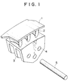
- FIG. 1 is a schematic perspective view illustrating one embodiment of the turbine blade (3) of the present invention.
- the turbine blade of FIG. 1 comprises a block composed of a shroud 1, three airfoils 2 and a root 3.
- This turbine blade may be connected to a rotor by boring through holes in root 3 constituting the lower part of the blade, and anchoring root 3 to the rotor with straight pins 5 inserted into these through holes 4.
- the rotor (not shown) also has through holes at the same positions as through holes 4, and root 3 is connected to the rotor by the expansion fitting of straight pins 5.
- airfoils 2 have a solid structure.
- This turbine blade is formed of a material having excellent high-temperature strength, and hence exhibits high reliability. Moreover, since this turbine blade is made by precision casting, the term of works and the manufacturing cost can be markedly reduced as compared with the conventional cutting process using a high-Cr forged steel material.
- the weight of airfoils 2 has been reduced by forming a cavity 6 in each airfoil 2. Since this can also reduce the stress produced at the root of the blade, the thickness of the root can be made smaller. As a result, moving blades having much lighter weight (e.g., by more than 10%) than ones of solid structure can be made. Eventually, the stress applied to the rotor can also be reduced by more than 10%.
- F mV 2 /r
- m the mass
- V the rotational speed
- r the radius of gyration
- FIG. 2 is a schematic perspective view illustrating one embodiment of the turbine blade (4) of the present invention
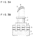
- FIG. 3(a) is a view showing the cross-sectional shape of an airfoil.
- the turbine blade of this embodiment may be anchored to a rotor by inserting straight pins 5 into through holes 4 bored in root 3 and rotor 7.
- each airfoil 2 have a cavity 6 formed therein for the purpose of reducing its weight, as illustrated in FIG. 3A.
- This hollow structure makes it possible to achieve a reduction in the weight of airfoils.
- the reduction in the weight of airfoils 2 causes a decrease in centrifugal force, so that the thickness of root 3 can be made smaller.
- the overall weight of the blade can be reduced by more than 10%. It is to be understood that, from the viewpoint of strength, the airfoils of hollow structure involve no problem because the strength of the blade itself can be sufficiently retained by the outer shells.
- the turbine blade (4) of the present invention is reduced in weight and hence makes it possible to relax the strength requirements for the rotor supporting the blade. Consequently, an inexpensive material may be used for the rotor.
- the present invention is also highly effective in reducing the cost of the rotor material. That is, the technique of the present invention which makes it possible to reduce the weight of blades may be said to be an epoch-making technique which makes it possible to improve the reliability of turbines and provide inexpensive turbine equipment.
- the aforesaid turbine blade (5) of the present invention is a turbine blade having airfoils of hollow structure in which the surface thereof is made smooth by forming a depression 10 in the shroud and mounting a metallic plate (or shroud cover) 8 in this depression by a suitable means such as electron beam welding.
- the line segment with arrow heads indicates the circumferential direction of the turbine.
- FIG. 4 One embodiment of the turbine blade (5) of the present invention in which the shroud has a depression formed in the surface thereof is illustrated in the schematic perspective view of FIG. 4, and the turbine blade of FIG. 4 in which a metallic plate (or shroud cover) is mounted in the depression of the shroud is illustrated in the schematic perspective view of FIG. 5.
- the turbine blade of this embodiment has such a structure that, in forming a blade shape according to a precision casting process, shroud 1 is provided with a depression 10 as illustrated in FIG. 4 so as to permit a shroud cover 8 comprising a metallic plate to be mounted on shroud 1.
- the mounting of shroud cover 8 on shroud 1 can be achieved by a welding process such as electron beam welding.
- the material of shroud cover 8 may be any material that can withstand the centrifugal force due to its self-weight at temperatures of 600°C or below.
- any type of material having high-temperature strength of not less than SUS410 class as specified by the Japanese Industrial Standards may be used without causing any particular problem.
- shroud cover 8 since the welded joints of shroud cover 8 only need to withstand the centrifugal force due to its self-weight, sufficient strength will be achieved by welding shroud cover 8 along two weld lines 9 extending in the circumferential direction of the turbine.
- the turbine blade (5) of the present invention has the effect of eliminating disturbances in a flow of fluid around the outer periphery of the blade as observed in the case in which the cavities of the airfoils are open to the surface of the shroud, and thereby preventing a reduction in thermal efficiency.
- the above-described high-Cr casting material (1) of the present invention has been developed by using a high-Cr steel as a basic material and modifying the contents of various ingredients, and hence has excellent high-temperature strength.
- this high-Cr casting material (1) various components requiring high-temperature strength can be made by precision casting.
- this high-Cr casting material is used as the structural material of turbine blades, they can be made by a precision casting process in place of the conventional cutting process using a high-Cr forged steel material. Consequently, a significant reduction in term of works and manufacturing cost can be achieved.
- the high-Cr casting material (2) of the present invention shows a further improvement in creep rupture strength.
- the turbine blade (3) of the present invention is formed of a material having excellent high-temperature strength, and hence exhibits high reliability. Moreover, since this turbine blade may be made by precision casting, it can be made with a shorter term of works and at a less manufacturing cost as compared with conventional blades made by the cutting of a high-Cr forged steel material.
- the turbine blade (4) of the present invention its airfoils are modified so as to have a hollow structure.
- this turbine blade has the effect of being reduced in weight.
- the lighter weight of the blade makes it possible to relax the strength requirements for the rotor supporting the blade. Consequently, an inexpensive material may be used for the rotor, resulting in a reduced cost of the rotor material.
- the surface thereof is made smooth by forming a depression in the shroud and mounting a shroud cover in this depression. Consequently, in addition to the effects possessed by the turbine blade (4) of the present invention, this turbine blade has the effect of eliminating disturbances in a flow of fluid around the outer periphery of the blade as observed in the case in which the cavities of the airfoils are open to the surface of the shroud, and thereby preventing a reduction in thermal efficiency.
- test materials were heat-treated by heating them at 1,050°C for 5 hours and then air-cooling them to 150°C or below. Then, they were tempered at their respective tempering temperatures which had been determined so as to give a 0.2% yield strength of about 70-80 kgf/mm 2 .
- the inventive materials (1) (test material Nos. 1-7) and comparative materials (test material Nos. 11-18) so prepared were subjected to room-temperature tension tests and impact tests. Moreover, the creep rupture strengths of these test materials after being held at 600°C for 100,000 hours were determined by extrapolation. The results thus obtained are shown in Table 2. As is evident from the results of the room-temperature tension tests, the ductility (as expressed by elongation and reduction of area) and impact value of the inventive materials are stably higher. In contrast, the ductility and toughness of the comparative materials are relatively lower. Moreover, it can be seen that the creep rupture strength of the inventive materials is much more excellent than that of the comparative materials. Group Test material No.
- inventive materials (2) (test material Nos. 21-25) so prepared were subjected to room-temperature tension tests and impact tests in the same manner as in Example 1. Moreover, the creep rupture strengths of the inventive materials (2) after being held at 600°C for 100,000 hours were determined by extrapolation. The results thus obtained are shown in Table 4. In Tables 3 and 4, data on test material Nos. 1, 4, 5 and 7 included in the inventive materials (1) obtained in Example 1 are also shown for purposes of comparison.
Landscapes
- Engineering & Computer Science (AREA)
- Chemical & Material Sciences (AREA)
- Mechanical Engineering (AREA)
- Materials Engineering (AREA)
- General Engineering & Computer Science (AREA)
- Metallurgy (AREA)
- Organic Chemistry (AREA)
- Turbine Rotor Nozzle Sealing (AREA)
Applications Claiming Priority (3)
| Application Number | Priority Date | Filing Date | Title |
|---|---|---|---|
| JP50428/97 | 1997-03-05 | ||
| JP5042897 | 1997-03-05 | ||
| JP9050428A JPH10245658A (ja) | 1997-03-05 | 1997-03-05 | 高Cr精密鋳造材及びタービン翼 |
Publications (2)
| Publication Number | Publication Date |
|---|---|
| EP0863221A1 true EP0863221A1 (fr) | 1998-09-09 |
| EP0863221B1 EP0863221B1 (fr) | 2000-05-03 |
Family
ID=12858605
Family Applications (1)
| Application Number | Title | Priority Date | Filing Date |
|---|---|---|---|
| EP98103275A Expired - Lifetime EP0863221B1 (fr) | 1997-03-05 | 1998-02-25 | Aubes de turnies |
Country Status (7)
| Country | Link |
|---|---|
| US (1) | US6095756A (fr) |
| EP (1) | EP0863221B1 (fr) |
| JP (1) | JPH10245658A (fr) |
| AT (1) | ATE192508T1 (fr) |
| CZ (1) | CZ290459B6 (fr) |
| DE (1) | DE69800133T2 (fr) |
| ES (1) | ES2149023T3 (fr) |
Cited By (3)
| Publication number | Priority date | Publication date | Assignee | Title |
|---|---|---|---|---|
| EP1347073A4 (fr) * | 2000-12-26 | 2006-01-18 | Japan Steel Works Ltd | Acier ferritique a forte teneur en chrome resistant aux hautes temperatures |
| US7281901B2 (en) | 2004-12-29 | 2007-10-16 | Caterpillar Inc. | Free-form welded power system component |
| EP3112597A1 (fr) | 2015-07-02 | 2017-01-04 | Airbus Defence and Space GmbH | Aube de turbine résistante à haute température avec couche d'oxyde céramique |
Families Citing this family (7)
| Publication number | Priority date | Publication date | Assignee | Title |
|---|---|---|---|---|
| US20040115059A1 (en) * | 2002-12-12 | 2004-06-17 | Kehl Richard Eugene | Cored steam turbine bucket |
| US7104762B2 (en) * | 2004-01-06 | 2006-09-12 | General Electric Company | Reduced weight control stage for a high temperature steam turbine |
| US20060088409A1 (en) * | 2004-10-21 | 2006-04-27 | General Electric Company | Grouped reaction nozzle tip shrouds with integrated seals |
| US20070071605A1 (en) * | 2005-09-23 | 2007-03-29 | General Electric Company | Integrated nozzle and bucket wheels for reaction steam turbine stationary components and related method |
| CN101629573B (zh) * | 2009-08-07 | 2011-08-10 | 宁波甬微集团有限公司 | 制冷压缩机滑片及其制造方法 |
| JP2015227627A (ja) * | 2014-05-30 | 2015-12-17 | 株式会社東芝 | 回転機械 |
| JP2017159350A (ja) * | 2016-03-11 | 2017-09-14 | 株式会社神戸製鋼所 | 溶接金属、および該溶接金属を含む溶接構造体 |
Citations (4)
| Publication number | Priority date | Publication date | Assignee | Title |
|---|---|---|---|---|
| JPH04371552A (ja) * | 1991-06-18 | 1992-12-24 | Nippon Steel Corp | 高強度フェライト系耐熱鋼 |
| JPH08333657A (ja) * | 1995-04-03 | 1996-12-17 | Japan Steel Works Ltd:The | 耐熱鋳鋼およびその製造方法 |
| JPH0931600A (ja) * | 1995-07-17 | 1997-02-04 | Mitsubishi Heavy Ind Ltd | 高温用蒸気タービンロータ材 |
| JPH0959747A (ja) * | 1995-08-25 | 1997-03-04 | Hitachi Ltd | 高強度耐熱鋳鋼,蒸気タービンケーシング,蒸気タービン発電プラント及び蒸気タービン |
Family Cites Families (17)
| Publication number | Priority date | Publication date | Assignee | Title |
|---|---|---|---|---|
| US3810711A (en) * | 1972-09-22 | 1974-05-14 | Gen Motors Corp | Cooled turbine blade and its manufacture |
| GB1483532A (en) * | 1974-09-13 | 1977-08-24 | Rolls Royce | Stator structure for a gas turbine engine |
| US4218178A (en) * | 1978-03-31 | 1980-08-19 | General Motors Corporation | Turbine vane structure |
| US4693667A (en) * | 1980-04-29 | 1987-09-15 | Teledyne Industries, Inc. | Turbine inlet nozzle with cooling means |
| EP0084234A1 (fr) * | 1981-12-16 | 1983-07-27 | Vickers Plc | Procédé pour le moulage de précision et moule |
| JPS61231139A (ja) * | 1985-04-06 | 1986-10-15 | Nippon Steel Corp | 高強度フエライト系耐熱鋼 |
| US4761116A (en) * | 1987-05-11 | 1988-08-02 | General Electric Company | Turbine blade with tip vent |
| JPH0639885B2 (ja) * | 1988-03-14 | 1994-05-25 | 株式会社日立製作所 | ガスタービン用シュラウド及びガスタービン |
| US5173255A (en) * | 1988-10-03 | 1992-12-22 | General Electric Company | Cast columnar grain hollow nickel base alloy articles and alloy and heat treatment for making |
| US5226789A (en) * | 1991-05-13 | 1993-07-13 | General Electric Company | Composite fan stator assembly |
| US5310431A (en) * | 1992-10-07 | 1994-05-10 | Robert F. Buck | Creep resistant, precipitation-dispersion-strengthened, martensitic stainless steel and method thereof |
| US5350277A (en) * | 1992-11-20 | 1994-09-27 | General Electric Company | Closed-circuit steam-cooled bucket with integrally cooled shroud for gas turbines and methods of steam-cooling the buckets and shrouds |
| US5415706A (en) * | 1993-05-28 | 1995-05-16 | Abb Management Ag | Heat- and creep-resistant steel having a martensitic microstructure produced by a heat-treatment process |
| JP3110227B2 (ja) * | 1993-11-22 | 2000-11-20 | 株式会社東芝 | タービン冷却翼 |
| JP3315800B2 (ja) * | 1994-02-22 | 2002-08-19 | 株式会社日立製作所 | 蒸気タービン発電プラント及び蒸気タービン |
| JPH08135402A (ja) * | 1994-11-11 | 1996-05-28 | Mitsubishi Heavy Ind Ltd | ガスタービン静翼構造 |
| JP3358951B2 (ja) * | 1996-09-10 | 2002-12-24 | 三菱重工業株式会社 | 高強度・高靱性耐熱鋳鋼 |
-
1997
- 1997-03-05 JP JP9050428A patent/JPH10245658A/ja not_active Withdrawn
-
1998
- 1998-02-25 ES ES98103275T patent/ES2149023T3/es not_active Expired - Lifetime
- 1998-02-25 AT AT98103275T patent/ATE192508T1/de not_active IP Right Cessation
- 1998-02-25 DE DE69800133T patent/DE69800133T2/de not_active Expired - Fee Related
- 1998-02-25 EP EP98103275A patent/EP0863221B1/fr not_active Expired - Lifetime
- 1998-03-03 CZ CZ1998634A patent/CZ290459B6/cs not_active IP Right Cessation
- 1998-03-03 US US09/034,065 patent/US6095756A/en not_active Expired - Fee Related
Patent Citations (4)
| Publication number | Priority date | Publication date | Assignee | Title |
|---|---|---|---|---|
| JPH04371552A (ja) * | 1991-06-18 | 1992-12-24 | Nippon Steel Corp | 高強度フェライト系耐熱鋼 |
| JPH08333657A (ja) * | 1995-04-03 | 1996-12-17 | Japan Steel Works Ltd:The | 耐熱鋳鋼およびその製造方法 |
| JPH0931600A (ja) * | 1995-07-17 | 1997-02-04 | Mitsubishi Heavy Ind Ltd | 高温用蒸気タービンロータ材 |
| JPH0959747A (ja) * | 1995-08-25 | 1997-03-04 | Hitachi Ltd | 高強度耐熱鋳鋼,蒸気タービンケーシング,蒸気タービン発電プラント及び蒸気タービン |
Non-Patent Citations (4)
| Title |
|---|
| PATENT ABSTRACTS OF JAPAN vol. 017, no. 247 (C - 1059) 18 May 1993 (1993-05-18) * |
| PATENT ABSTRACTS OF JAPAN vol. 097, no. 004 30 April 1997 (1997-04-30) * |
| PATENT ABSTRACTS OF JAPAN vol. 097, no. 006 30 June 1997 (1997-06-30) * |
| PATENT ABSTRACTS OF JAPAN vol. 097, no. 007 31 July 1997 (1997-07-31) * |
Cited By (4)
| Publication number | Priority date | Publication date | Assignee | Title |
|---|---|---|---|---|
| EP1347073A4 (fr) * | 2000-12-26 | 2006-01-18 | Japan Steel Works Ltd | Acier ferritique a forte teneur en chrome resistant aux hautes temperatures |
| US7820098B2 (en) | 2000-12-26 | 2010-10-26 | The Japan Steel Works, Ltd. | High Cr ferritic heat resistance steel |
| US7281901B2 (en) | 2004-12-29 | 2007-10-16 | Caterpillar Inc. | Free-form welded power system component |
| EP3112597A1 (fr) | 2015-07-02 | 2017-01-04 | Airbus Defence and Space GmbH | Aube de turbine résistante à haute température avec couche d'oxyde céramique |
Also Published As
| Publication number | Publication date |
|---|---|
| CZ63498A3 (cs) | 1999-11-17 |
| EP0863221B1 (fr) | 2000-05-03 |
| CZ290459B6 (cs) | 2002-07-17 |
| ES2149023T3 (es) | 2000-10-16 |
| US6095756A (en) | 2000-08-01 |
| DE69800133T2 (de) | 2000-11-09 |
| ATE192508T1 (de) | 2000-05-15 |
| JPH10245658A (ja) | 1998-09-14 |
| DE69800133D1 (de) | 2000-06-08 |
Similar Documents
| Publication | Publication Date | Title |
|---|---|---|
| EP0384433B1 (fr) | Acier ferritique résistant à la chaleur et présentant une excellente résistance mécanique aux températures élevées | |
| KR0175075B1 (ko) | 증기터빈용 회전자 및 그 제조방법 | |
| JP3354832B2 (ja) | 高靭性フェライト系耐熱鋼 | |
| EP1001044B1 (fr) | Utilisation d'un acier coulé thérmoresistant | |
| US6350325B1 (en) | Turbine shaft and method for producing a turbine shaft | |
| US5882586A (en) | Heat-resistant nickel-based alloy excellent in weldability | |
| US6095756A (en) | High-CR precision casting materials and turbine blades | |
| US4857120A (en) | Heat-resisting steel turbine part | |
| EP2204462A1 (fr) | Alliage à base de Ni pour une pièce forgée d'une turbine à vapeur avec une excellente résistance à haute température, forgeabilité et soudabilité, pale de rotor d'une turbine à vapeur, pale de stator d'une turbine à vapeur, élément à vis de turbine à vapeur, et tuyau d'une turbine à vapeur | |
| US6106766A (en) | Material for gas turbine disk | |
| JP3422658B2 (ja) | 耐熱鋼 | |
| JPS616256A (ja) | 12%Cr耐熱鋼 | |
| JPH0672286B2 (ja) | ▲高▼温強度に優れたオーステナイト系ステンレス鋼 | |
| US20010041137A1 (en) | Steam turbine rotor shaft | |
| JP2001049398A (ja) | 高靭性耐熱鋼およびタービンロータの製造方法 | |
| JP3245097B2 (ja) | 高温用蒸気タービンロータ材 | |
| JPH06256893A (ja) | 高温強度に優れた高靭性低合金鋼 | |
| JPH02149649A (ja) | Cr合金鋼 | |
| JPS61217554A (ja) | 12Cr耐熱鋼 | |
| Ishii et al. | High strength 12% Cr heat resisting steel for high temperature steam turbine blade | |
| JPS61221355A (ja) | 12Cr耐熱鋼 | |
| KR20230090346A (ko) | Z상 형성이 지연된 마르텐사이트 강, 분말 및 블랭크 또는 부품 | |
| JPH08246096A (ja) | 回転体用低合金鋼 | |
| JPH0570902A (ja) | 高Cr合金鋼 | |
| JPH0650041B2 (ja) | ガスタ−ビン |
Legal Events
| Date | Code | Title | Description |
|---|---|---|---|
| PUAI | Public reference made under article 153(3) epc to a published international application that has entered the european phase |
Free format text: ORIGINAL CODE: 0009012 |
|
| 17P | Request for examination filed |
Effective date: 19980225 |
|
| AK | Designated contracting states |
Kind code of ref document: A1 Designated state(s): AT BE CH DE ES FR GB IT LI NL SE |
|
| AX | Request for extension of the european patent |
Free format text: AL;LT;LV;MK;RO;SI |
|
| 17Q | First examination report despatched |
Effective date: 19981126 |
|
| AKX | Designation fees paid |
Free format text: AT BE CH DE ES FR GB IT LI NL SE |
|
| RBV | Designated contracting states (corrected) |
Designated state(s): AT BE CH DE ES FR GB IT LI NL SE |
|
| RTI1 | Title (correction) |
Free format text: TURBINE BLADES |
|
| GRAG | Despatch of communication of intention to grant |
Free format text: ORIGINAL CODE: EPIDOS AGRA |
|
| GRAG | Despatch of communication of intention to grant |
Free format text: ORIGINAL CODE: EPIDOS AGRA |
|
| GRAG | Despatch of communication of intention to grant |
Free format text: ORIGINAL CODE: EPIDOS AGRA |
|
| GRAH | Despatch of communication of intention to grant a patent |
Free format text: ORIGINAL CODE: EPIDOS IGRA |
|
| RTI1 | Title (correction) |
Free format text: TURBINE BLADES |
|
| GRAG | Despatch of communication of intention to grant |
Free format text: ORIGINAL CODE: EPIDOS AGRA |
|
| GRAH | Despatch of communication of intention to grant a patent |
Free format text: ORIGINAL CODE: EPIDOS IGRA |
|
| GRAH | Despatch of communication of intention to grant a patent |
Free format text: ORIGINAL CODE: EPIDOS IGRA |
|
| GRAA | (expected) grant |
Free format text: ORIGINAL CODE: 0009210 |
|
| AK | Designated contracting states |
Kind code of ref document: B1 Designated state(s): AT BE CH DE ES FR GB IT LI NL SE |
|
| REF | Corresponds to: |
Ref document number: 192508 Country of ref document: AT Date of ref document: 20000515 Kind code of ref document: T |
|
| REG | Reference to a national code |
Ref country code: CH Ref legal event code: EP |
|
| REF | Corresponds to: |
Ref document number: 69800133 Country of ref document: DE Date of ref document: 20000608 |
|
| REG | Reference to a national code |
Ref country code: CH Ref legal event code: NV Representative=s name: BUECHEL, KAMINSKI & PARTNER PATENTANWAELTE EST |
|
| ITF | It: translation for a ep patent filed | ||
| ET | Fr: translation filed | ||
| REG | Reference to a national code |
Ref country code: GB Ref legal event code: 746 Effective date: 20000911 |
|
| REG | Reference to a national code |
Ref country code: ES Ref legal event code: FG2A Ref document number: 2149023 Country of ref document: ES Kind code of ref document: T3 |
|
| REG | Reference to a national code |
Ref country code: FR Ref legal event code: D6 |
|
| PLBE | No opposition filed within time limit |
Free format text: ORIGINAL CODE: 0009261 |
|
| STAA | Information on the status of an ep patent application or granted ep patent |
Free format text: STATUS: NO OPPOSITION FILED WITHIN TIME LIMIT |
|
| 26N | No opposition filed | ||
| REG | Reference to a national code |
Ref country code: GB Ref legal event code: IF02 |
|
| PGFP | Annual fee paid to national office [announced via postgrant information from national office to epo] |
Ref country code: SE Payment date: 20030205 Year of fee payment: 6 |
|
| PGFP | Annual fee paid to national office [announced via postgrant information from national office to epo] |
Ref country code: FR Payment date: 20030210 Year of fee payment: 6 |
|
| PGFP | Annual fee paid to national office [announced via postgrant information from national office to epo] |
Ref country code: AT Payment date: 20030212 Year of fee payment: 6 |
|
| PGFP | Annual fee paid to national office [announced via postgrant information from national office to epo] |
Ref country code: GB Payment date: 20030219 Year of fee payment: 6 |
|
| PGFP | Annual fee paid to national office [announced via postgrant information from national office to epo] |
Ref country code: NL Payment date: 20030226 Year of fee payment: 6 Ref country code: ES Payment date: 20030226 Year of fee payment: 6 |
|
| PGFP | Annual fee paid to national office [announced via postgrant information from national office to epo] |
Ref country code: CH Payment date: 20030228 Year of fee payment: 6 |
|
| PGFP | Annual fee paid to national office [announced via postgrant information from national office to epo] |
Ref country code: DE Payment date: 20030306 Year of fee payment: 6 |
|
| PGFP | Annual fee paid to national office [announced via postgrant information from national office to epo] |
Ref country code: BE Payment date: 20030425 Year of fee payment: 6 |
|
| PG25 | Lapsed in a contracting state [announced via postgrant information from national office to epo] |
Ref country code: GB Free format text: LAPSE BECAUSE OF NON-PAYMENT OF DUE FEES Effective date: 20040225 Ref country code: AT Free format text: LAPSE BECAUSE OF NON-PAYMENT OF DUE FEES Effective date: 20040225 |
|
| PG25 | Lapsed in a contracting state [announced via postgrant information from national office to epo] |
Ref country code: SE Free format text: LAPSE BECAUSE OF NON-PAYMENT OF DUE FEES Effective date: 20040226 Ref country code: ES Free format text: LAPSE BECAUSE OF NON-PAYMENT OF DUE FEES Effective date: 20040226 |
|
| PG25 | Lapsed in a contracting state [announced via postgrant information from national office to epo] |
Ref country code: BE Free format text: LAPSE BECAUSE OF NON-PAYMENT OF DUE FEES Effective date: 20040228 |
|
| PG25 | Lapsed in a contracting state [announced via postgrant information from national office to epo] |
Ref country code: LI Free format text: LAPSE BECAUSE OF NON-PAYMENT OF DUE FEES Effective date: 20040229 Ref country code: CH Free format text: LAPSE BECAUSE OF NON-PAYMENT OF DUE FEES Effective date: 20040229 |
|
| BERE | Be: lapsed |
Owner name: *MITSUBISHI HEAVY INDUSTRIES LTD Effective date: 20040228 |
|
| PG25 | Lapsed in a contracting state [announced via postgrant information from national office to epo] |
Ref country code: NL Free format text: LAPSE BECAUSE OF NON-PAYMENT OF DUE FEES Effective date: 20040901 Ref country code: DE Free format text: LAPSE BECAUSE OF NON-PAYMENT OF DUE FEES Effective date: 20040901 |
|
| EUG | Se: european patent has lapsed | ||
| GBPC | Gb: european patent ceased through non-payment of renewal fee |
Effective date: 20040225 |
|
| REG | Reference to a national code |
Ref country code: CH Ref legal event code: PL |
|
| PG25 | Lapsed in a contracting state [announced via postgrant information from national office to epo] |
Ref country code: FR Free format text: LAPSE BECAUSE OF NON-PAYMENT OF DUE FEES Effective date: 20041029 |
|
| NLV4 | Nl: lapsed or anulled due to non-payment of the annual fee |
Effective date: 20040901 |
|
| REG | Reference to a national code |
Ref country code: FR Ref legal event code: ST |
|
| PG25 | Lapsed in a contracting state [announced via postgrant information from national office to epo] |
Ref country code: IT Free format text: LAPSE BECAUSE OF NON-PAYMENT OF DUE FEES;WARNING: LAPSES OF ITALIAN PATENTS WITH EFFECTIVE DATE BEFORE 2007 MAY HAVE OCCURRED AT ANY TIME BEFORE 2007. THE CORRECT EFFECTIVE DATE MAY BE DIFFERENT FROM THE ONE RECORDED. Effective date: 20050225 |
|
| REG | Reference to a national code |
Ref country code: ES Ref legal event code: FD2A Effective date: 20040226 |