EP0863314A1 - Compresseur à canal latéral effilé - Google Patents
Compresseur à canal latéral effilé Download PDFInfo
- Publication number
- EP0863314A1 EP0863314A1 EP98103724A EP98103724A EP0863314A1 EP 0863314 A1 EP0863314 A1 EP 0863314A1 EP 98103724 A EP98103724 A EP 98103724A EP 98103724 A EP98103724 A EP 98103724A EP 0863314 A1 EP0863314 A1 EP 0863314A1
- Authority
- EP
- European Patent Office
- Prior art keywords
- side channel
- cross
- section
- channel
- flow guide
- Prior art date
- Legal status (The legal status is an assumption and is not a legal conclusion. Google has not performed a legal analysis and makes no representation as to the accuracy of the status listed.)
- Granted
Links
- 239000007789 gas Substances 0.000 claims abstract description 26
- 230000006835 compression Effects 0.000 abstract description 2
- 238000007906 compression Methods 0.000 abstract description 2
- 230000006698 induction Effects 0.000 abstract 1
- 238000013461 design Methods 0.000 description 5
- 230000003716 rejuvenation Effects 0.000 description 3
- 238000011161 development Methods 0.000 description 2
- 230000000694 effects Effects 0.000 description 2
- 230000015572 biosynthetic process Effects 0.000 description 1
- 230000008878 coupling Effects 0.000 description 1
- 238000010168 coupling process Methods 0.000 description 1
- 238000005859 coupling reaction Methods 0.000 description 1
- 230000008030 elimination Effects 0.000 description 1
- 238000003379 elimination reaction Methods 0.000 description 1
- 230000001771 impaired effect Effects 0.000 description 1
- 238000012986 modification Methods 0.000 description 1
- 230000004048 modification Effects 0.000 description 1
- 238000012545 processing Methods 0.000 description 1
- 238000012546 transfer Methods 0.000 description 1
Images


Classifications
-
- F—MECHANICAL ENGINEERING; LIGHTING; HEATING; WEAPONS; BLASTING
- F04—POSITIVE - DISPLACEMENT MACHINES FOR LIQUIDS; PUMPS FOR LIQUIDS OR ELASTIC FLUIDS
- F04D—NON-POSITIVE-DISPLACEMENT PUMPS
- F04D23/00—Other rotary non-positive-displacement pumps
- F04D23/008—Regenerative pumps
Definitions
- the invention relates to a side channel compressor according to the preamble of the claim 1.
- the invention is therefore based on the object, the side channel compressor Elimination of the disadvantages outlined so that improved Efficiency an increase in volume flow with a uniform Pressure increase in the side channel results.
- the side channel compressor designed according to the invention has a modified one Cross section of the side channel, in such a way that the cross section of the side channel tapers from the suction side towards the pressure side.
- the structural design is expediently provided in such a way that the suction side has a larger cross section of the side channel, and preferably by at least a factor of 1.15 compared to the pressure side of the side channel, and that this cross section of the side channel towards the pressure side rejuvenated.
- cross section of the side channel is continuous or continuously rejuvenated.
- this advantageous embodiment results from this embodiment according to the invention achieved that the enlarged channel cross-section in the suction area improved Expansion of the gas ensures that the pressure side through the interrupter entry. This means that a vacuum can also be achieved at a lower level and the suction power increases.
- the cross-sectional taper of the side channel is 20-40%.
- the side channel Housing cover an inward-pointing flow guide edge for the pumped Media arranged.
- This flow guide edge is in the form of a tapered Rib formed, advantageously the cross section of the flow leading edge adapted to the tapering cross section of the side channel is.
- the flow guide edge can be formed in one piece with the wall of the side channel be. Instead, the flow leading edge can also be on a separate Guide ring formed in the side channel at the corresponding desired Place used on the inner wall or attached there.
- a side channel compressor has impeller equipped with blades, which is used to compress gases in one Housing is rotatable.
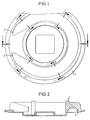
- the housing is provided with a cover 1, which has a gas inlet 2 and a Has gas outlet 3 and, as can be clearly seen from Fig. 2, on the impeller facing side a side channel 4 limited.
- the cross section of the side channel 4 is bowl-shaped and designed such that he from the gas inlet 2 (suction side) towards the gas outlet 3 (pressure side) rejuvenated.
- the tapering of the side channel cross section takes place in the illustrated Embodiment continuously or continuously.
- the cross-sectional taper is in the embodiment shown such that the cross section of the side channel 4 at the point D - D according to 1 in the manner shown in FIG. 6 is 130%. Tapered from here then the cross section of the side channel 4 steadily over 122% of the Interface C - C according to FIG. 1 (see FIG. 5) and over 107% at the interface B - B according to FIG. 1 (see FIG. 4) except for 100% at the interface A - A or near the gas outlet 3 (see Fig. 3).
- a flow guide edge 5 which tapers conically is formed and points inward in the manner shown.
- This flow leading edge 5 is formed in one piece with the wall of the side channel 4 and serves for the corresponding redirection of the flow of the media to be conveyed the outer area of the side channel 4. This will result in a better deflection the flow, which results in an efficiency improvement of 5 to 9%.
- the formation of the flow leading edge 5 over the entire circumference of the side channel 4 is selected such that the cross section of the flow guide edge 5 on the tapering cross section of the side channel 4 is adapted.
- the flow guide edge 5 is integrally formed with the wall of the side channel 4, is in the modified embodiment according to FIGS. 8 and 9 on the flow guide edge 5 a separate guide ring 6 is provided, which in the manner shown in FIG. 8 is formed and inserted into the interior of the side channel 4 or there is attached that the flow guide edge 5 in the same manner as in the previously described Embodiment according to FIG. 7 shows inwards.
- This one too Embodiment becomes the same effect in efficiency improvement as achieved in the embodiment of FIG. 7.
- FIGS. 10 and 11, 12 serve as a supplementary explanation the operation of a side channel blower and show schematically in Fig. 10 a side channel blower with a single ring impeller 7 in radial Type with a semicircular cross section of the side channel 4, wherein the side channel is formed in the housing or cover 1.
- the in Fig. 10 The arrows shown represent the flow of the media to be pumped, in such a way that the open impeller 7 with its blades to be promoted Medium pushes out of the impeller 7 and this against the wall of the in the cover 1 side channel 4 presses. From there the flow becomes like this deflected that the medium to be conveyed is pressed into the impeller 7 again.
- a so-called double-flow side channel compressor is provided.
- the impeller 7 is formed with a double blade ring, one blade assembly from the other blade assembly is averted.
- Each blade ring unit is a side channel 4, which on one Lid is arranged, assigned.
- FIG. 13 shows a development of the side channel 4 on the suction or pressure side can be seen.
- the cross section of the side channel 4 at the gas inlet 2 is separated from the gas outlet 3 by an interrupter web 8, opposite the Cross section near the gas outlet expanded by the amount that by the hatched area 9 is marked.
Landscapes
- Engineering & Computer Science (AREA)
- Mechanical Engineering (AREA)
- General Engineering & Computer Science (AREA)
- Structures Of Non-Positive Displacement Pumps (AREA)
- Applications Or Details Of Rotary Compressors (AREA)
- Compressors, Vaccum Pumps And Other Relevant Systems (AREA)
Applications Claiming Priority (2)
| Application Number | Priority Date | Filing Date | Title |
|---|---|---|---|
| DE19708952A DE19708952A1 (de) | 1997-03-05 | 1997-03-05 | Seitenkanalverdichter mit sich verjüngendem Kanalquerschnitt |
| DE19708952 | 1997-03-05 |
Publications (2)
| Publication Number | Publication Date |
|---|---|
| EP0863314A1 true EP0863314A1 (fr) | 1998-09-09 |
| EP0863314B1 EP0863314B1 (fr) | 2002-10-02 |
Family
ID=7822304
Family Applications (1)
| Application Number | Title | Priority Date | Filing Date |
|---|---|---|---|
| EP98103724A Revoked EP0863314B1 (fr) | 1997-03-05 | 1998-03-03 | Compresseur à canal latéral effilé |
Country Status (3)
| Country | Link |
|---|---|
| EP (1) | EP0863314B1 (fr) |
| DE (2) | DE19708952A1 (fr) |
| ES (1) | ES2180084T3 (fr) |
Cited By (5)
| Publication number | Priority date | Publication date | Assignee | Title |
|---|---|---|---|---|
| WO2000058629A1 (fr) * | 1999-03-26 | 2000-10-05 | Werner Rietschle Gmbh + Co. Kg | Compresseur a conduit lateral |
| EP1672222A3 (fr) * | 2004-12-17 | 2007-04-04 | Gardner Denver Elmo Technology GmbH | Compresseur à canal latéral |
| WO2007146882A1 (fr) * | 2006-06-12 | 2007-12-21 | Mag Aerospace Industries, Inc. | Pompe à vide régénérative pour avion et autres véhicules |
| WO2009059719A1 (fr) | 2007-11-05 | 2009-05-14 | Gardner Denver Deutschland Gmbh | Compresseur à canal latéral |
| US20160010659A1 (en) * | 2014-07-09 | 2016-01-14 | Mag Aerospace Industries, Llc | Vacuum generator flow diverter |
Families Citing this family (2)
| Publication number | Priority date | Publication date | Assignee | Title |
|---|---|---|---|---|
| US11441772B2 (en) | 2018-07-19 | 2022-09-13 | Brunswick Corporation | Forced-draft pre-mix burner device |
| DE102024106999A1 (de) * | 2024-03-12 | 2025-09-18 | Truma Gerätetechnik GmbH & Co. KG | Seitenkanalverdichter mit optimierter Einlassöffnungsgeometrie |
Citations (7)
| Publication number | Priority date | Publication date | Assignee | Title |
|---|---|---|---|---|
| GB606127A (en) * | 1944-10-30 | 1948-08-06 | Bendix Aviat Corp | Blowers |
| DE876285C (de) * | 1940-09-29 | 1953-05-11 | Siemens Ag | Ringverdichter |
| FR2144287A5 (fr) * | 1971-06-26 | 1973-02-09 | Siemens Ag | |
| US4325672A (en) * | 1978-12-15 | 1982-04-20 | The Utile Engineering Company Limited | Regenerative turbo machine |
| SU1359437A1 (ru) * | 1986-03-25 | 1987-12-15 | Ленинградский Кораблестроительный Институт | Вихрева турбомашина |
| DE4220153A1 (de) * | 1991-06-18 | 1992-12-24 | Hitachi Ltd | Wirbelstromgeblaese |
| EP0602558A1 (fr) * | 1992-12-16 | 1994-06-22 | Alcatel SEL Aktiengesellschaft | Dispositif de transport d'un médium gazeux |
-
1997
- 1997-03-05 DE DE19708952A patent/DE19708952A1/de not_active Withdrawn
-
1998
- 1998-03-03 ES ES98103724T patent/ES2180084T3/es not_active Expired - Lifetime
- 1998-03-03 DE DE59805750T patent/DE59805750D1/de not_active Expired - Fee Related
- 1998-03-03 EP EP98103724A patent/EP0863314B1/fr not_active Revoked
Patent Citations (7)
| Publication number | Priority date | Publication date | Assignee | Title |
|---|---|---|---|---|
| DE876285C (de) * | 1940-09-29 | 1953-05-11 | Siemens Ag | Ringverdichter |
| GB606127A (en) * | 1944-10-30 | 1948-08-06 | Bendix Aviat Corp | Blowers |
| FR2144287A5 (fr) * | 1971-06-26 | 1973-02-09 | Siemens Ag | |
| US4325672A (en) * | 1978-12-15 | 1982-04-20 | The Utile Engineering Company Limited | Regenerative turbo machine |
| SU1359437A1 (ru) * | 1986-03-25 | 1987-12-15 | Ленинградский Кораблестроительный Институт | Вихрева турбомашина |
| DE4220153A1 (de) * | 1991-06-18 | 1992-12-24 | Hitachi Ltd | Wirbelstromgeblaese |
| EP0602558A1 (fr) * | 1992-12-16 | 1994-06-22 | Alcatel SEL Aktiengesellschaft | Dispositif de transport d'un médium gazeux |
Non-Patent Citations (1)
| Title |
|---|
| DATABASE WPI Section PQ Week 8827, 9 July 1988 Derwent World Patents Index; Class Q51, AN 88-189594, XP002067222 * |
Cited By (12)
| Publication number | Priority date | Publication date | Assignee | Title |
|---|---|---|---|---|
| WO2000058629A1 (fr) * | 1999-03-26 | 2000-10-05 | Werner Rietschle Gmbh + Co. Kg | Compresseur a conduit lateral |
| CN1119531C (zh) * | 1999-03-26 | 2003-08-27 | 维尔纳·里彻尔两合公司 | 侧通道压缩机 |
| US6779968B1 (en) | 1999-03-26 | 2004-08-24 | Werner Rietsche Gmbh & Co., Kg | Side channel compressor |
| EP1672222A3 (fr) * | 2004-12-17 | 2007-04-04 | Gardner Denver Elmo Technology GmbH | Compresseur à canal latéral |
| WO2007146882A1 (fr) * | 2006-06-12 | 2007-12-21 | Mag Aerospace Industries, Inc. | Pompe à vide régénérative pour avion et autres véhicules |
| WO2009059719A1 (fr) | 2007-11-05 | 2009-05-14 | Gardner Denver Deutschland Gmbh | Compresseur à canal latéral |
| US20110052378A1 (en) * | 2007-11-05 | 2011-03-03 | Gardner Denver Deutschland Gmbh | Side channel compressor |
| CN101842598B (zh) * | 2007-11-05 | 2012-11-07 | 加德纳·丹佛德国股份有限公司 | 侧通道压缩机 |
| US8662822B2 (en) * | 2007-11-05 | 2014-03-04 | Gardner Denver Deutschland Gmbh | Side channel compressor |
| TWI479082B (zh) * | 2007-11-05 | 2015-04-01 | Gardner Denver Gmbh | 側通道壓縮機 |
| KR101540999B1 (ko) * | 2007-11-05 | 2015-07-31 | 가드너 덴버 도이칠란트 게엠베하 | 사이드 채널형 컴프레셔 |
| US20160010659A1 (en) * | 2014-07-09 | 2016-01-14 | Mag Aerospace Industries, Llc | Vacuum generator flow diverter |
Also Published As
| Publication number | Publication date |
|---|---|
| DE59805750D1 (de) | 2002-11-07 |
| EP0863314B1 (fr) | 2002-10-02 |
| DE19708952A1 (de) | 1998-09-17 |
| ES2180084T3 (es) | 2003-02-01 |
Similar Documents
| Publication | Publication Date | Title |
|---|---|---|
| DE69216938T2 (de) | Verdichtergehäuse für Turbolader | |
| DE19518101C2 (de) | Seitenkanalpumpe | |
| EP0081456B1 (fr) | Pompe à tourbillon | |
| DE2811724A1 (de) | Zentrifugalverdichter und verdichtergehaeuse | |
| DE69101953T2 (de) | Mehrphasige Pump- oder Kompressionsvorrichtung und ihre Anwendung. | |
| EP0614014A1 (fr) | Compresseur radial avec un carter stabilisant l'écoulement de fluides | |
| DE10327574A1 (de) | Laufrad für eine Kraftstoffpumpe | |
| DE19647605A1 (de) | Abgas-Turbolader für Brennkraftmaschinen | |
| DE10327573B4 (de) | Einstufige Strömungspumpe | |
| DE19602368A1 (de) | Radialgebläse | |
| DE69104455T2 (de) | Regenerativkreiselverdichter. | |
| DE3238972A1 (de) | Horizontal geteiltes gehaeuse einer stroemungsmaschine | |
| EP0863314A1 (fr) | Compresseur à canal latéral effilé | |
| DE2652642A1 (de) | Axialventilator mit der aussenkontur eines ein paar quadratische begrenzungsflaechen aufweisenden quaders | |
| DE3001868A1 (de) | Kreiselpumpe mit doppelspiralgehaeuse | |
| DE10200176B4 (de) | Elektrokraftstoffpumpe | |
| WO1995025895A1 (fr) | Dispositif pour reduire le bruit de pompes centrifuges | |
| DE19913950A1 (de) | Seitenkanalverdichter | |
| DE2545036A1 (de) | Gehaeuse fuer ein querstromgeblaese | |
| DE1264675B (de) | Vorrichtung zum Verstellen der Stroemungsquerschnitte von Diffusoren bei einer Turbomaschine | |
| EP0316470B1 (fr) | Ventilateur radial avec volute interne | |
| EP0845600A2 (fr) | Machine à canal latéral | |
| DE4106614A1 (de) | Vorrichtung zur kennlinienstabilisierung fuer radialverdichter | |
| DE19757580A1 (de) | Seitenkanalpumpe mit Seitenkanal im Ansaugdeckel zur Vermeidung verlustbehafteter Wirbelstrukturen | |
| DE2525316A1 (de) | Laufrad-anordnung fuer zentrifugalpumpen |
Legal Events
| Date | Code | Title | Description |
|---|---|---|---|
| PUAI | Public reference made under article 153(3) epc to a published international application that has entered the european phase |
Free format text: ORIGINAL CODE: 0009012 |
|
| AK | Designated contracting states |
Kind code of ref document: A1 Designated state(s): DE ES FR IT SE |
|
| AX | Request for extension of the european patent |
Free format text: AL;LT;LV;MK;RO;SI |
|
| 17P | Request for examination filed |
Effective date: 19990305 |
|
| AKX | Designation fees paid |
Free format text: DE ES FR IT SE |
|
| RBV | Designated contracting states (corrected) |
Designated state(s): DE ES FR IT SE |
|
| 17Q | First examination report despatched |
Effective date: 20010425 |
|
| GRAG | Despatch of communication of intention to grant |
Free format text: ORIGINAL CODE: EPIDOS AGRA |
|
| GRAG | Despatch of communication of intention to grant |
Free format text: ORIGINAL CODE: EPIDOS AGRA |
|
| GRAH | Despatch of communication of intention to grant a patent |
Free format text: ORIGINAL CODE: EPIDOS IGRA |
|
| GRAH | Despatch of communication of intention to grant a patent |
Free format text: ORIGINAL CODE: EPIDOS IGRA |
|
| GRAA | (expected) grant |
Free format text: ORIGINAL CODE: 0009210 |
|
| AK | Designated contracting states |
Kind code of ref document: B1 Designated state(s): DE ES FR IT SE |
|
| PG25 | Lapsed in a contracting state [announced via postgrant information from national office to epo] |
Ref country code: FR Free format text: LAPSE BECAUSE OF FAILURE TO SUBMIT A TRANSLATION OF THE DESCRIPTION OR TO PAY THE FEE WITHIN THE PRESCRIBED TIME-LIMIT Effective date: 20021002 |
|
| REF | Corresponds to: |
Ref document number: 59805750 Country of ref document: DE Date of ref document: 20021107 |
|
| PG25 | Lapsed in a contracting state [announced via postgrant information from national office to epo] |
Ref country code: SE Free format text: LAPSE BECAUSE OF FAILURE TO SUBMIT A TRANSLATION OF THE DESCRIPTION OR TO PAY THE FEE WITHIN THE PRESCRIBED TIME-LIMIT Effective date: 20030102 |
|
| REG | Reference to a national code |
Ref country code: ES Ref legal event code: FG2A Ref document number: 2180084 Country of ref document: ES Kind code of ref document: T3 |
|
| PLBQ | Unpublished change to opponent data |
Free format text: ORIGINAL CODE: EPIDOS OPPO |
|
| PLBI | Opposition filed |
Free format text: ORIGINAL CODE: 0009260 |
|
| EN | Fr: translation not filed | ||
| PLAX | Notice of opposition and request to file observation + time limit sent |
Free format text: ORIGINAL CODE: EPIDOSNOBS2 |
|
| 26 | Opposition filed |
Opponent name: NASH-ELMO INDUSTRIES GMBH Effective date: 20030701 |
|
| PLBB | Reply of patent proprietor to notice(s) of opposition received |
Free format text: ORIGINAL CODE: EPIDOSNOBS3 |
|
| RDAF | Communication despatched that patent is revoked |
Free format text: ORIGINAL CODE: EPIDOSNREV1 |
|
| RDAG | Patent revoked |
Free format text: ORIGINAL CODE: 0009271 |
|
| STAA | Information on the status of an ep patent application or granted ep patent |
Free format text: STATUS: PATENT REVOKED |
|
| 27W | Patent revoked |
Effective date: 20030925 |